

PLX wideband install


Well, I still have'nt received the replacement power cord for my wideband, so today I called them to check up on it. They said it was shipping out today. WTF? I called MONDAY! Stupid bastards, it doesnt take 4 days to throw a little power cord in a padded envelope and ship it out. ESPECIALLY when their dumbasses are the ones that sent out bad ones that were specifically set aside as "defective". I swear there are so many stupid asses in the world it's pathetic 
Originally Posted by 97rs4life
cool cool, those pics are great. Any idea how to run a wire to hptuners or the egr connection? Does it go in one of those empty slots on that white connector?
http://www.rdmelton.autoeducation.co.../wideband.html
and here's the thread that gives the details about how to make the connection:
https://ls1tech.com/forums/pcm-diagnostics-tuning/451779-hooking-up-wb-another-sensor-egr-read-into-hpt.html

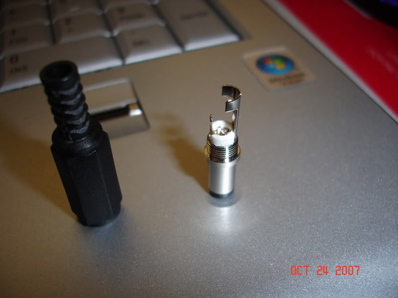
Which connector on this thingamijig is considered the center and which is considered the shield as per the instructions.?
"solder or crimp the red power wire to the center of the connector."
"solder or crimp the black power wire to the shield of the connector."
Edit** next question, where do the wires go once you make them for the white analog plug? do they hook into the plug up there in the picture? the directions with this are very counterproductive!!
Also, where have yall been placing the red box, im not neseccarily looking for hidden places, just havent seen any pics of where to place this contraption.
Thanks in advance
Tom
Last edited by 1FAST02FORMULAHAWK; Oct 24, 2007 at 05:27 PM.
the small connector on the left of the picture is the center (where the red goes).
the large connector on the right of the picture is the shield (where the black goes).
Where the wires go from the white plug depends on what you are doing with the wideband. Do you have a display gauge? Are you sending a wideband (0-5volt) output to some sort of logging device (HP Tuners, EFI Live, etc) and/or are you sending a narrowband (0-1 volt) output to the stock ECU to replace a factory o2 sensor?
Here are some pictures of my installation. (I installed the box under the passenger side kick panel. )
http://rdmelton.autoeducation.com/ca.../wideband.html
edit - add link
Last edited by rdmelton; Oct 25, 2007 at 05:46 AM. Reason: add link


