


Nitrous Wiring Inquiry
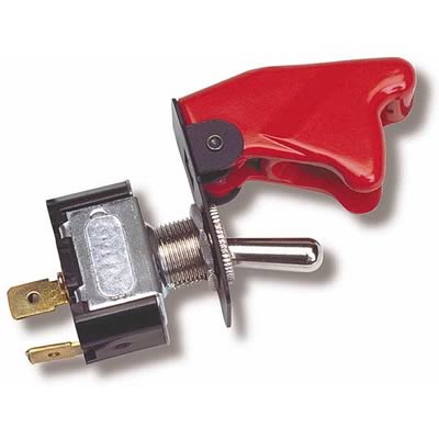
I am currently trying to finish my 'other' Pontiac and have a question about wiring the nitrous. I installed a hobbs switch but am unsure where to connect it on the activation switch. The switch has three connectors and I do not know which one the hobbs should attach too. The instructions only show two connectors. Any help would be appreciated.


TECH Regular
Joined: Nov 2001
Posts: 422
Likes: 0
From: Yakima, WA
In your picture of the WOT switch, use the spade on the right. Labeled "NO" Normally open. When the Linkage hits WOT the circuit closes and you're in business...
Ellis explained the hobbs switch abit if you're confused on it.
Am I a guru now? LOL
Ellis explained the hobbs switch abit if you're confused on it.
Am I a guru now? LOL

10 Second Club
Joined: Jul 2005
Posts: 702
Likes: 0
Trending Topics
Joined: Nov 2001
Posts: 10,023
Likes: 6
From: LT1 land...the "409" of the 90s!
LS1 Tech Stories
The Best V8 Stories One Small Block at Time

6 Common C5 Corvette Failures and What's Involved In Repairing Them
Pouria Savadkouei
Retro Modern Bandit Pontiac Trans AM Comes With Burt Reynolds' Autograph
Verdad Gallardo
Top 10 Greatest Cadillac V Series Performance Models Ever, Ranked
Pouria Savadkouei
Top 10 Most Powerful Chevy Trucks Ever Made!

Hennessey's New Supercharged Silverado ZR2 Has 700 HP
Verdad Gallardo
Coachbuilt N2A Anteros Is an LS2-Powered C6 Corvette In Italian Clothes
Verdad Gallardo
Awesome K5 Blazer Restomod Comes With C7 Corvette Power
Verdad Gallardo
10 Camaros You Should Never Buy

10 LS Engine Myths That Refuse to Die
Verdad Gallardo ***Back at this again***
I am at the point to wire the toggle switch but mine only has two prongs, not three as indicated by the schematic above. Does that mean it is a self ground type? Can I omit the ground and attach one prong to the microswitch and the other to the key on power? And if so does it matter which prong connects to what wire since it isnt marked?
I am at the point to wire the toggle switch but mine only has two prongs, not three as indicated by the schematic above. Does that mean it is a self ground type? Can I omit the ground and attach one prong to the microswitch and the other to the key on power? And if so does it matter which prong connects to what wire since it isnt marked?
10 Second Club
Joined: Jul 2005
Posts: 702
Likes: 0
***Back at this again***
I am at the point to wire the toggle switch but mine only has two prongs, not three as indicated by the schematic above. Does that mean it is a self ground type? Can I omit the ground and attach one prong to the microswitch and the other to the key on power? And if so does it matter which prong connects to what wire since it isnt marked?

I am at the point to wire the toggle switch but mine only has two prongs, not three as indicated by the schematic above. Does that mean it is a self ground type? Can I omit the ground and attach one prong to the microswitch and the other to the key on power? And if so does it matter which prong connects to what wire since it isnt marked?


10 Second Club
Joined: Jul 2005
Posts: 702
Likes: 0
I found this great description as a first hit on Live Search...
Don't wory about the diode thing. It shouldn't be a problem in your case.
http://www.the12volt.com/relays/relays.asp
SPDT Relay : (Single Pole Double Throw Relay) an electromagnetic switch, consist of a coil (terminals 85 & 86), 1 common terminal (30), 1 normally closed terminal (87a), and one normally open terminal (87).
When the coil of the relay is at rest (not energized), the common terminal (30) and the normally closed terminal (87a) have continuity. When the coil is energized, the common terminal (30) and the normally open terminal (87) have continuity.
The diagram below center shows the relay at rest, with the coil not energized. The diagram below right shows the relay with the coil energized. As you can see the coil is an electromagnet that causes the arm that is always connected to the common (30) to pivot when energized whereby contact is broken from the normally closed terminal (87a) and made with the normally open terminal (87).
SPST Relay : (Single Pole Single Throw Relay) an electromagnetic switch, consist of a coil (terminals 85 & 86), 1 common terminal (30), and one normally open terminal (87). It does not have a normally closed terminal like the SPDT relay, but may be used in place of SPDT relays in all diagrams shown on this site where terminal 87a is not used.
When energizing the coil of a relay, polarity of the coil does not matter unless there is a diode across the coil. If a diode is not present, you may attach positive voltage to either terminal of the coil and negative voltage to the other, otherwise you must connect positive to the side of the coil that the cathode side (side with stripe) of the diode is connected and negative to side of the coil that the anode side of the diode is connected.


Diodes are most often used across the coil to provide a path for current when the current path to the relay is interrupted (i.e. switched off, coil no longer energized). This allows the coil field to collapse without the voltage spike that would otherwise be generated. The diode protects switch or relay contacts and other circuits that may be sensitive to voltage spikes. (JimR, contributor, install bay member)
Why do I want to use a relay and do I really need to? Anytime you want to switch a device which draws more current than is provided by an output of a switch or component you'll need to use a relay. The coil of an SPDT relay that we most commonly use draws very little current (less than 200 milliamps) and the amount of current that you can pass through a relay's common, normally closed, and normally open contacts will handle up to 30 or 40 amps. This allows you to switch devices such as headlights, parking lights, horns, etc., with low amperage outputs such as those found on keyless entry and alarm systems, and other components. In some cases you may need to switch multiple things at the same time using one output. A single output connected to multiple relays will allow you to open continuity and/or close continuity simultaneously on multiple wires.
There are far too many applications to list that require the use of a relay, but we do show many of the most popular applications in the pages that follow. If you are still unclear about what a relay does or if you should use one after you browse through the rest of this section, please post a question at the12volt's install bay. (We recommend Bosch or Potter & Brumfield relays for all of the SPDT relay applications shown on this site.)
Don't wory about the diode thing. It shouldn't be a problem in your case.
http://www.the12volt.com/relays/relays.asp
SPDT Relay : (Single Pole Double Throw Relay) an electromagnetic switch, consist of a coil (terminals 85 & 86), 1 common terminal (30), 1 normally closed terminal (87a), and one normally open terminal (87).
When the coil of the relay is at rest (not energized), the common terminal (30) and the normally closed terminal (87a) have continuity. When the coil is energized, the common terminal (30) and the normally open terminal (87) have continuity.
The diagram below center shows the relay at rest, with the coil not energized. The diagram below right shows the relay with the coil energized. As you can see the coil is an electromagnet that causes the arm that is always connected to the common (30) to pivot when energized whereby contact is broken from the normally closed terminal (87a) and made with the normally open terminal (87).
SPST Relay : (Single Pole Single Throw Relay) an electromagnetic switch, consist of a coil (terminals 85 & 86), 1 common terminal (30), and one normally open terminal (87). It does not have a normally closed terminal like the SPDT relay, but may be used in place of SPDT relays in all diagrams shown on this site where terminal 87a is not used.
When energizing the coil of a relay, polarity of the coil does not matter unless there is a diode across the coil. If a diode is not present, you may attach positive voltage to either terminal of the coil and negative voltage to the other, otherwise you must connect positive to the side of the coil that the cathode side (side with stripe) of the diode is connected and negative to side of the coil that the anode side of the diode is connected.
Diodes are most often used across the coil to provide a path for current when the current path to the relay is interrupted (i.e. switched off, coil no longer energized). This allows the coil field to collapse without the voltage spike that would otherwise be generated. The diode protects switch or relay contacts and other circuits that may be sensitive to voltage spikes. (JimR, contributor, install bay member)
Why do I want to use a relay and do I really need to? Anytime you want to switch a device which draws more current than is provided by an output of a switch or component you'll need to use a relay. The coil of an SPDT relay that we most commonly use draws very little current (less than 200 milliamps) and the amount of current that you can pass through a relay's common, normally closed, and normally open contacts will handle up to 30 or 40 amps. This allows you to switch devices such as headlights, parking lights, horns, etc., with low amperage outputs such as those found on keyless entry and alarm systems, and other components. In some cases you may need to switch multiple things at the same time using one output. A single output connected to multiple relays will allow you to open continuity and/or close continuity simultaneously on multiple wires.
There are far too many applications to list that require the use of a relay, but we do show many of the most popular applications in the pages that follow. If you are still unclear about what a relay does or if you should use one after you browse through the rest of this section, please post a question at the12volt's install bay. (We recommend Bosch or Potter & Brumfield relays for all of the SPDT relay applications shown on this site.)
nice find dragracer. thats a perty good writup on relays. thru trial and error ive leaned to use relays over the years. that clearified the differance between single and double throw relays and the use of the 87a terminal. i was unsure that it switched off when energized. i just got done rewiring a whole car one relay and wire at a time for fuel pump, two fans, water pump, and two stages of juice. and getting rid of unneeded wires along the way. its been fun