

stock tachometer not working
 09-27-2010, 06:13 PM
#21

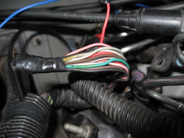
Here is the bundle of wires. There are 12 Total on this bundle of wires. Colors are as follows:
(2) Solid Gray
(2) Solid Black
(2) Solid Red
(1) Solid Green
(1) Solid Brown
(2) Pink w/ Black Stripe
(2) Brown w/ White Stripe
There is another single Solid Red wire on another bundle of wires right behind it. It is sticking up and has electrical tape covering the end.
I know that the (1) Solid Green wire and (1) Solid Black wire go to the A/C connector. That eliminates (2) wires.
Here's the question now. After we determine which wires need to be connected, can I just strip them and solder them together, or will I need the connector pieces?
 09-27-2010, 06:30 PM
#22
BLUE PCM CONNECTOR
41
BLACK
EGR Pintle Position. Sensor Ground.
47
GRAY
EGR Pintle Position. Sensor 5V REF
55
BROWN
EGR Pintle Position. Sensor Signal
61
PNK/BLK
Camshaft Position. Sensor Ref. Low
73
BRN/WHT
Camshaft Position. Sensor Signal
RED PCM CONNECTOR
7
RED
EGR Control
39
RED
Camshaft Position. Sensor B+ Supply
41
GRAY
EGR Position Sensor Ground
This info taken from: http://www.ls2.com/boggs/torques/99pinpcm.htm
These (8) wires listed take care of (10) wires with the (2) A/C wires included of the (12) wires. I am still missing the purpose of (1) PINK/BLACK wire and (1) BROWN/WHITE
41
BLACK
EGR Pintle Position. Sensor Ground.
47
GRAY
EGR Pintle Position. Sensor 5V REF
55
BROWN
EGR Pintle Position. Sensor Signal
61
PNK/BLK
Camshaft Position. Sensor Ref. Low
73
BRN/WHT
Camshaft Position. Sensor Signal
RED PCM CONNECTOR
7
RED
EGR Control
39
RED
Camshaft Position. Sensor B+ Supply
41
GRAY
EGR Position Sensor Ground
This info taken from: http://www.ls2.com/boggs/torques/99pinpcm.htm
These (8) wires listed take care of (10) wires with the (2) A/C wires included of the (12) wires. I am still missing the purpose of (1) PINK/BLACK wire and (1) BROWN/WHITE
Last edited by djfury05; 09-27-2010 at 06:47 PM.
09-27-2010, 08:34 PM
#23
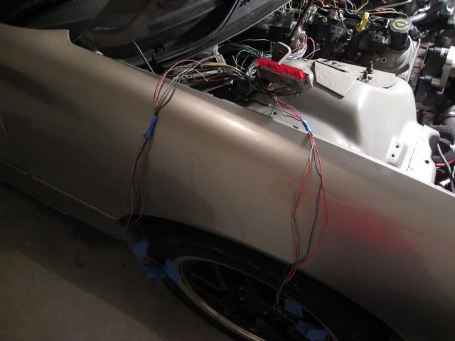
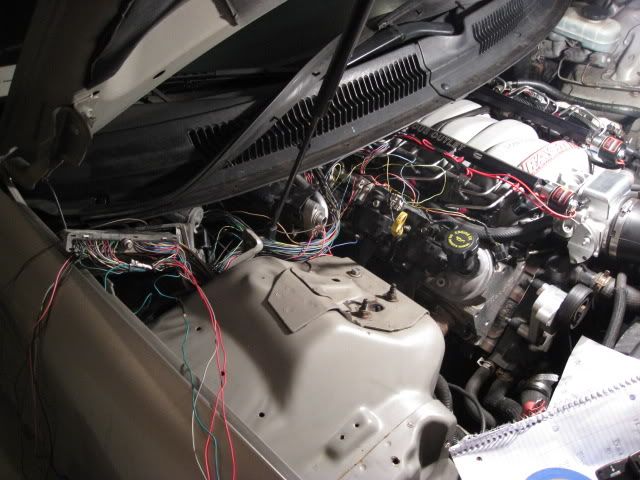
*UPDATE* I have taken apart the wiring harness and traced each wire listed above ^^ back to the PCM. There are 4 wires that do not lead to either the blue or red connector on the PCM, rather behind the intake in another wire loom that I haven't traced.
These are the 4 wires leading back behind the intake. (1) each: Solid Black, Pink/Black, Solid Red, and Brown/White.
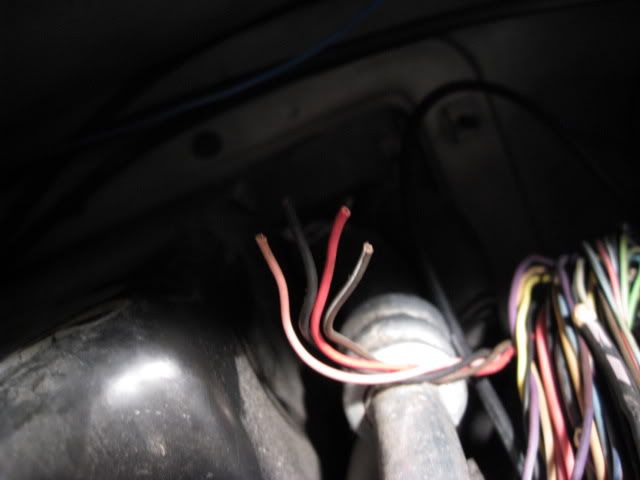
These are the other wires I have already traced.
These are the 4 wires leading back behind the intake. (1) each: Solid Black, Pink/Black, Solid Red, and Brown/White.
These are the other wires I have already traced.
09-27-2010, 09:32 PM
#24

Shoot me a call at my shop tomorrow.I'm pretty sure a customer is dropping off a 00 Z around 10am. On the phone I can atleast tell you the colors.The other side would be the 3-4 wires that don't go back to the pcm. Should be easy enough to figure out.
09-28-2010, 09:04 AM
#25
I believe I've got it figured out.. the 4 wires in back need to be connected to RED 41, 61, 73, and BLUE 39. All the colors correspond and if on original wiring, there were 2 connectors, male/female, this is why there would be extra wires that I can't find where they are going. I am going to splice and try it after I give Slowhawk a call
 10-04-2010, 11:43 AM
#31
Teching In
Join Date: Jun 2009
Location: nj
Posts: 32
Likes: 0
Received 0 Likes
on
0 Posts
hey guys may i ask what wires you ended up putting together i have same problem i had cut those wires off also and i noticed the same problem i have a 99 trans am so i have a strong feeling what djfury05 said is the cause of it .
Last edited by ls1racer1999; 10-04-2010 at 02:37 PM.
 05-17-2023, 08:48 AM
#33
TECH Senior Member
