
Issues with 4l80e lockup...
 03-26-2012, 03:40 PM
#1
TECH Fanatic
Thread Starter
iTrader: (5)
Join Date: Sep 2008
Location: Salem/Keizer
Posts: 1,120
Likes: 0
Received 0 Likes
on
0 Posts

I posted this in the Transmission section as well, as I'm not sure if the problem is related to the PCM or transmission....
I have a 2001 4l80e (FLT "level 5") with a 3400 stall/multi-disk lockup converter in my Fbody that is being controlled by a "411" PCM...I'm using the relay mod to allow correct transmission control, while using the 4l60e control segment. I'm having lockup issues. When I'm cruising on the highway (70-80 MPH), it will sometimes rapidly cycle in and out of lockup. When this starts happening, I'm able to use HPtuners to command lockup, and the problem seems to cease. The issue will rear its head at various trans temps...sometimes cold, sometimes hot.
I have not yet checked line pressures, but will do so in the next week. I'm wondering if anyone else has experienced this issue. PWM control of the TCC % is set to minimum=100,max=100.
Any thoughts?


 03-26-2012, 09:23 PM
#4
TECH Fanatic
Thread Starter
iTrader: (5)
Join Date: Sep 2008
Location: Salem/Keizer
Posts: 1,120
Likes: 0
Received 0 Likes
on
0 Posts
2002 camaro 4l60e segment....using reverse shift solenoid relay mod. Only issue seems to be lockup. And it's not a constant issue.
Thanks. I'll look into it...seems odd to be anything like that, as I can sometimes cruise for an hour without issue...then it just starts acting up.
Thanks. I'll look into it...seems odd to be anything like that, as I can sometimes cruise for an hour without issue...then it just starts acting up.
03-27-2012, 10:31 AM
#5
TECH Senior Member
If you didn't move pin s then you're driving the 4L80E TCC PWM signal from the 4L60E 3-2 control solenoid on/off signal.
If you're driving the 4L80E TCC PWM signal from the 4L60E TCC PWM signal, then that won't work correctly (the PCM occasionally spikes/parks the 4L60E TCC PWM at 100% while the TCC is unlocked).
You have to do either of these:
- drive the 4L80E TCC PWM signal from the 4L60E TCC on/off signal;
- drive the 4L80E TCC PWM signal from the 4L60E TCC PWM signal gated thru a relay controlled by the 4L60E TCC on/off signal.
edit: correction (I left out a signal name)
Last edited by joecar; 03-27-2012 at 05:14 PM. Reason: I left out a signal name
03-27-2012, 10:40 AM
#6
TECH Fanatic
Thread Starter
iTrader: (5)
Join Date: Sep 2008
Location: Salem/Keizer
Posts: 1,120
Likes: 0
Received 0 Likes
on
0 Posts
Very good info, Joe. Thanks. I'll have to double-check the wiring. I'm going to try to data log it on the way to work this morning as well to see exactly what is going on.
EDIT....data log added. Looks like no lockup at all on the way to work this AM. Last night, it was operating/locking up as it should...but no dice this morning.
EDIT....data log added. Looks like no lockup at all on the way to work this AM. Last night, it was operating/locking up as it should...but no dice this morning.
Last edited by salemetro; 03-27-2012 at 12:23 PM.
03-27-2012, 01:42 PM
#7
TECH Fanatic
Thread Starter
iTrader: (5)
Join Date: Sep 2008
Location: Salem/Keizer
Posts: 1,120
Likes: 0
Received 0 Likes
on
0 Posts
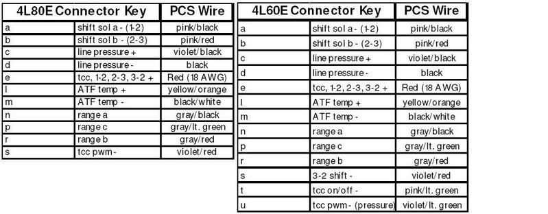
This is the wiring instruction sheet that I followed originally...in addition to wiring in the "reverse polarity" relay for the 2-3 (iirc) shift solenoid. Sorry for being a little foggy on this, but I'm having trouble sorting all this out in my head....as far as what I've done already, and what I have left to do. Anyone else feel like helping me sort this out?
Last edited by salemetro; 03-27-2012 at 01:52 PM.
Trending Topics
 sorry I was in a hurry this morning.
03-27-2012, 05:16 PM
sorry I was in a hurry this morning.
03-27-2012, 05:16 PM
#9
The pcm misfire calculation gets screwed up when ever there is an aftermarket converter installed because they are a smaller diameter. This makes the pcm think there is a misfire and it unlocks the converter. It is always random. Since you can command it locked I would have to say it is wired correctly. Disable the misfire detection and if you still have problems then look else where.
03-27-2012, 06:11 PM
#10
TECH Fanatic
Thread Starter
iTrader: (5)
Join Date: Sep 2008
Location: Salem/Keizer
Posts: 1,120
Likes: 0
Received 0 Likes
on
0 Posts
The pcm misfire calculation gets screwed up when ever there is an aftermarket converter installed because they are a smaller diameter. This makes the pcm think there is a misfire and it unlocks the converter. It is always random. Since you can command it locked I would have to say it is wired correctly. Disable the misfire detection and if you still have problems then look else where.
Last edited by salemetro; 03-27-2012 at 06:35 PM.
03-27-2012, 11:52 PM
#11
TECH Fanatic
Thread Starter
iTrader: (5)
Join Date: Sep 2008
Location: Salem/Keizer
Posts: 1,120
Likes: 0
Received 0 Likes
on
0 Posts
[B][QUOTE=joecar;16128016]
If you're driving the 4L80E TCC PWM signal from the 4L60E TCC PWM signal, then that won't work correctly (the PCM occasionally spikes/parks the 4L60E TCC PWM at 100% while the TCC is unlocked).
This appears to be what is happening, being that I'm able to drive at times with the PWM signal at 100%, with the converter in an unlocked status/state....sometimes for 20-40 miles.
You have to do either of these:
Option 1- drive the 4L80E TCC PWM signal from the 4L60E TCC on/off signal;
Option 2- drive the 4L80E TCC PWM signal from the 4L60E TCC PWM signal gated thru a relay controlled by the 4L60E TCC on/off signal.
Okay...so If I'm understanding correctly, option #1 will give me a simple "on or off" lockup control. Correct? This seems like the way I should go.
And option 2 would allow me to utilize PWM lockup or "Percentage of lockup" control. Correct?
So, my solution SHOULD be to just move pin "t" (4l60e tcc solenoid control) in the attached diagram to pin "s" (4l80e PWM solenoid) in the diagram then? Then just leave the old pin "s" wire not connected to anything, correct? Does this make sense? It's late, and I'm really trying to solve this....probably making it more difficult than it really is.
Last edited by salemetro; 03-28-2012 at 01:28 AM.
03-28-2012, 04:35 AM
#12
TECH Senior Member
Correct on your summary of options 1 and 2.
Yes, correct, use harness pin t to drive sub-harness pin s... and ignore the harness pins s and u.
[i.e. remove pin s from the harness connector, and in its place move pin t; I would also remove pin u ]
More info, see post #5 here.
Yes, correct, use harness pin t to drive sub-harness pin s... and ignore the harness pins s and u.
[i.e. remove pin s from the harness connector, and in its place move pin t; I would also remove pin u ]
More info, see post #5 here.
03-28-2012, 10:43 AM
#13
TECH Fanatic
Thread Starter
iTrader: (5)
Join Date: Sep 2008
Location: Salem/Keizer
Posts: 1,120
Likes: 0
Received 0 Likes
on
0 Posts
I can't thank you enough, Joecar! This has been a real source of frustration...nice to have a light at the end of the tunnel  A big shout out to edcmat-l1 as well for helping me out with the misfire detection corrections....thanks Ed!
A big shout out to edcmat-l1 as well for helping me out with the misfire detection corrections....thanks Ed! Last edited by salemetro; 03-28-2012 at 11:45 AM.
03-28-2012, 07:11 PM
#15
TECH Senior Member
Ok, I found out that there may be some 4L60E segments that park the TCC PWM at zero while the TCC is off (this is contrary to what the HMTG says), in which case you can safely drive the 4L80E TCC PWM signal from the 4L60E TCC PWM signal...
but if you do this, log TCC PWM DC and TCC on/off so you can see what the signals are doing (in particular look for what TCC PWM does when TCC on/off is off).
but if you do this, log TCC PWM DC and TCC on/off so you can see what the signals are doing (in particular look for what TCC PWM does when TCC on/off is off).
Last edited by joecar; 03-28-2012 at 08:08 PM. Reason: typo
03-28-2012, 07:50 PM
#16
TECH Fanatic
Thread Starter
iTrader: (5)
Join Date: Sep 2008
Location: Salem/Keizer
Posts: 1,120
Likes: 0
Received 0 Likes
on
0 Posts
The problem with mine, is that tcc pwm is parked at 100%....and the tcc is in an unlocked state most of the time. See my posted data log.....
03-28-2012, 09:27 PM
#19
TECH Senior Member
Ok, I see it, TCC PWM parked at 100% while TCC is off (I have a collection of logs also showing this).
I also see that the commanded TCC stays off (even tho car is doing 77 mph with steady throttle and zero total misfire count)...
I also see that the commanded TCC stays off (even tho car is doing 77 mph with steady throttle and zero total misfire count)...