
Aeroforce Interceptor Gauge Owners
 01-08-2013, 07:02 AM
#21

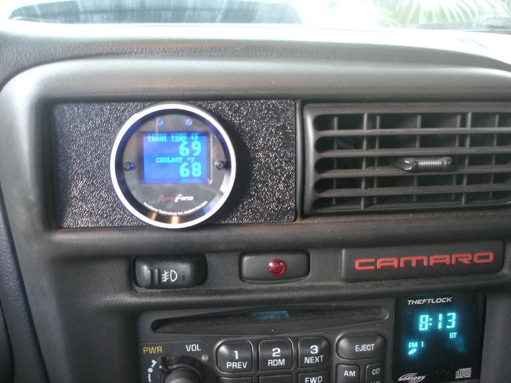
Ok so according to this thread https://ls1tech.com/forums/automatic...blem-help.html when the trans temp reads 250, that's when damage starts to occur, also a side note, the aeroforce interceptor reads 5-10 degrees Farenheit higher than other gauges read for the trans temp according to that thread. If anyone wants to confirm that, be sure to chime in.
Last edited by Roarin_8; 01-08-2013 at 10:05 AM.

 01-08-2013, 09:38 AM
#23
https://ls1tech.com/forums/pcm-diagn...or-wiring.html
01-08-2013, 10:25 AM
#24
7-Trans temps- This question gets ask a lot. What’s TOO HOT? Well ideally you want you average temp to stay under 190 degrees however I would not get to concerned till the temps get at and or over 230 degrees. Heat can damage a trans but with the exception of extreme heat 250 or higher this damage is a long term killer by breaking down fluid and causing rubber seals to harden and break.
The thread that quote was in is here https://ls1tech.com/forums/automatic...questions.html
01-08-2013, 10:41 AM
#25
Ok, as far as voltage for o2 sensors:
Thread where the quote was taken from: https://ls1tech.com/forums/general-m...-readings.html
How are you checking them? First of all, engine needs to be warm. Second, RPM should be revved up to about 2500 to get a nice exhaust stream over the sensors.
Voltage should constantly fluctuate between .125v and .875v. This up and down should happen a few times every second.
Average should be about .450v.
Voltage should constantly fluctuate between .125v and .875v. This up and down should happen a few times every second.
Average should be about .450v.
01-08-2013, 10:51 AM
#26
If you want to use the gauge to see what your 1/4 mile time and trap speed are, this is a good read: https://ls1tech.com/forums/drag-raci...erceptors.html
01-08-2013, 11:04 AM
#28
TECH Fanatic
I have one but I haven't used it much. I just set it up real quick with RPM, MPH, Trans Temp, and Throttle Position. I haven't had a chance to mount it (I got a single pod that needs painted and drilled into the A-Pillar  ) but I would hook it up and then set it in the cupholder for temporary use. It is a pretty nice gauge just need to get it setup to actually use it right
) but I would hook it up and then set it in the cupholder for temporary use. It is a pretty nice gauge just need to get it setup to actually use it right
01-08-2013, 11:15 AM
#29
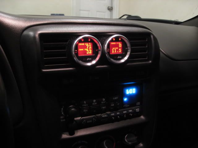
Good idea for the thread OP.. I've got dual Aeroforce gauges and currently monitor: Coolant temp, Intake Air temp, Battery, and my Wideband. I've got a lot of different parameters setup on each gauge but quite a few don't even read anything. I haven't went back into them since I've got them to change things around. Trans temp won't work for M6 trans or I'd prolly monitor that also.
01-08-2013, 11:21 AM
#30
Good idea for the thread OP.. I've got dual Aeroforce gauges and currently monitor: Coolant temp, Intake Air temp, Battery, and my Wideband. I've got a lot of different parameters setup on each gauge but quite a few don't even read anything. I haven't went back into them since I've got them to change things around. Trans temp won't work for M6 trans or I'd prolly monitor that also.
 01-08-2013, 11:29 AM
#31

I've had my Aeroforce gauge for about 6 years and it's been in two different cars, I love it! Great customer service too. Lets not forget about the built in shift light, although I wish it was slightly brighter.
01-08-2013, 11:37 AM
#32
Luckily I already had a bung welded into my y-pipe so it was very easy to install. I mounted the little black box in the bottom of that picture in the link in the glove box for easy access. You will need to solder in 12v and find a ground. The rest is plug and play and it comes with directions on how to configure the Aeroforce gauge to recognize the wideband sensor and how to display it correctly.
What pics you looking for? Basically you have the o2 sensor in the y-pipe, the harness from that o2 sensor to the little black box, another harness from the little black box to the back of the Aeroforce gauge, and the last harness is the power/ground harness.
01-08-2013, 11:52 AM
#33
I bought this http://marylandspeed.com/aeroforce-s...bk-p-2518.html
Luckily I already had a bung welded into my y-pipe so it was very easy to install. I mounted the little black box in the bottom of that picture in the link in the glove box for easy access. You will need to solder in 12v and find a ground. The rest is plug and play and it comes with directions on how to configure the Aeroforce gauge to recognize the wideband sensor and how to display it correctly.
What pics you looking for? Basically you have the o2 sensor in the y-pipe, the harness from that o2 sensor to the little black box, another harness from the little black box to the back of the Aeroforce gauge, and the last harness is the power/ground harness.
01-08-2013, 12:17 PM
#35
Supported parameters for GM vehicles straight from aeroforce's website:
A1A-GM Supported Parameters (PID’S)
1. INTAKE AIR- Intake Air Temperature - **
2. COOLANT TEMP- Engine Coolant Temperature **
3. TRANS TEMP 1- Transmission Temperature for automatic gas vehicles
4. TRANS TEMP 2- Trans temp for some vehicles made from ’94-’97.
4. RPM- engine Revolutions Per Minute **
5. MAF SENSOR LB/M- Mass Air Flow (lbs/min) **
6. MAF FREQUENCY- raw Mass Air Flow sensor output (frequency)
7. MAF FREQUENCY 2- raw MAF sensor output for the Cobalt SS and Redline
8. MAP SENSOR- Manifold Air Pressure (kPa) **
9. BOOST – Intake vacuum/boost displayed in inHg/PSI. Corrected by altitude entry or barometer**
9. THROTTLE POS. PCT- Throttle Position percentage (0-100%)
10. THROTTLE VOLTS- Throttle Position sensor output (0-5 volts)
11. MILES PER HOUR- Miles Per Hour **
12. KNOCK RETARD- Knock Retard (degrees) for most GM vehicles
13. KNOCK RETARD 2- used for KR value of ’94-’97 LT1’s and some 96/97 V8’s.
14. KNOCK RETARD 3- used for knock retard value of the Cobalt SS SC and Redline
15. IGNITION ADVANCE- ignition timing advance
16. PULSE WIDTH- injector #1 pulse width (4&6 cylinder engines)
17. SHORT TRIM B1-short term fuel trim bank#1
18. SHORT TRIM B2-short term fuel trim bank#2
19. LONG TRIM B1-long term fuel trim bank#1
20. LONG TRIM B2-long term fuel trim bank#2
21. OXYGEN SENSOR B1-O2 bank 1 sensor 1 in millivolts
22. OXYGEN SENSOR B2-O2 bank 2 sensor 1 in millivolts
23. OXYGEN SENSOR – alternate O2 sensor parameter, rarely supported.
24. RUN TIME MINS- engine run time is tenths of seconds since last engine start **
25. BATTERY VOLTAGE- Alternator/battery output voltage **
26. IAC POSITION- Idle Air Control counts (position of Idle Air Control valve)
27. PULSE WIDTH B1-injector Pulse Width for bank 1 (8 cylinder engines)
28. PULSE WIDTH B2-injector Pulse Width for bank 2 (8 cylinder engines)
29. ENGINE LOAD- calculated Engine Load (0-100%) **
30. ENGINE OIL PRESSURE (some 8 cylinder engines) **
31. INTAKE AIR 2 – Intake Air Temp. downstream of intercooler (some supercharged applications such as the
Cobalt SS, Ion Redline).
32. TRANS TEMP AL- Allison transmission temp, Duramax and Workhorse
33. TORQUE CONVERTER SLIP AL- Allison transmission converter slip, Duramax and Workhorse
34. TQ TO TRANS AL- Engine torque delivered to trans, Duramax and Workhorse
35. INJECTOR RAIL PRESSURE DESIRED DM- Duramax
36. INJECTOR RAIL PRESSURE ACTUAL DM- Duramax
37. THROTTLE PCT DM- Throttle percentage- Duramax
38. THROTTLE VOLTS DM- Throttle sensor voltage- Duramax
39. FUEL LEVEL DM- Duramax
40. INJECTOR FLOW RATE DM- Duramax
41. Desired Turbo Vane Position- 2004+ Duramax
42. Actual Turbo Vane Position- 2004+ Duramax
43. Pilot Injector Pulse Width- pilot injector pulse width in msec. - Duramax
44. Main Injector Pulse Width- main injector pulse width in msec. - Duramax
45. Pilot Injector Timing- in degrees - Duramax
46. Main Injector Timing- in degrees - Duramax
47. Pilot Injector Fuel Rate- mm^3 - Duramax
48. Main Injector Fuel Rate- mm^3 - Duramax
49. Miles Per Gallon 1- instantaneous fuel economy for gas vehicles
50. Miles Per Gallon 2- instantaneous fuel economy for diesel vehicles
51. HP 1- Calculated net horsepower for gasoline vehicles
52. HP 2- Calculated net horsepower for diesel vehicles
53. Analog 1 – analog input #1.
54. Analog 2 – analog input #2
55. TOTAL MISFIRES- Total misfires of all cylinders. Resets every minute.
56. BAROMETRIC PRESSURE- limited support on standard GM vehicles, DM support
57. PITCH – H2 Hummer support – indicates the angle of inclination of the vehicle.
58. CURRENT GEAR- Current gear of the transmission
59. TORQUE- Calculated torque from engine to transmission
60. SHIFT TIME- time (msec) for last shift to occur
61. TORQUE CONVERTER SLIP – Amount of slip allowed by torque converter
62. TORQUE CONVERTER STATUS- Indicates whether torque converter is locked (L) or unlocked (UL)
**These standard GM parameters also are supported by the Duramax diesel
Bi-directional controls:
1. Fan 1-3 control
2. PCM (fuel trim) reset
3. CASE (Crank Angle Sensor Error) Re- Learn
01-09-2013, 03:41 PM
#36
I love my aeroforce gauge. I usually have it on coolant/Trans temp. I have it set up to read IAT, battery, my o2 sensors, timing, throttle position and fuel %.
I have a 98 so to answer someone's earlier post yes I need to hardware it.
I originally had it mounted in the vent under the a pillar then moved it to a single pod on the pillar.
I have a 98 so to answer someone's earlier post yes I need to hardware it.
I originally had it mounted in the vent under the a pillar then moved it to a single pod on the pillar.
01-09-2013, 04:31 PM
#37
10 Second Club
iTrader: (14)

Join Date: Dec 2005
Location: Central California
Posts: 1,392
Likes: 0
Received 0 Likes
on
0 Posts

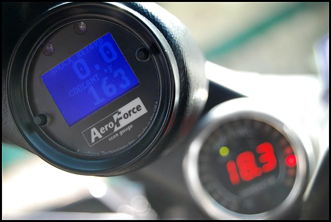
I use mine to monitor mainly AFR and Knock Retard on my Z28. I have an AEM wideband that the aeroforce piggybacks off of to get the right signal for AFR. I have the annunciator on the aeroforce set to monitor KR, and anything above 0.00 will make the lights flash red. This alone has saved me a few times.
01-13-2013, 08:06 AM
#38
Basically I'm lookng for any positive number. If I remember correctly the annunciation setting will depend when the warning lights come on due to the sensitivity. I set it up years ago though so I don't remember exactly.