When you click on links to various merchants on this site and make a purchase, this can result in this site earning a commission. Affiliate programs and affiliations include, but are not limited to, the eBay Partner Network.
I'm starting this thread to create a project log for my suspension and brake upgrade to follow my work progress over the next few weeks and to keep specific notes and how-to's on each item as I tackle them.
I'm going to be performing the work on my 94 Formula. This car is not my daily and I put less than 1,000 miles on it per year. It's used for pleasure, weekend cruises, car shows, and I'm planning on getting my feet wet with some autocross and road racing so that is what I'm going to be setting it up for.
Below is my parts list.
Suspension
BMR Lowering Springs - SP090
BMR Sway Bar Kit w. Bushings Front & Rear - SB026
BMR Lowering Springs - SP001
Koni Single Adjustable Front Shocks - 8241 1139SPORT
Koni Single On-Car Adjustable Rear Shocks - 8241 1140SPORT
Founders LCA Relocation Brackets - 23881
Spohn Shock Tower Brace - 964
Used OEM Front Upper & Lower Control Arms w UCA Mounts
Used OEM Rear Lower Control Arms
Panhard Bar - Yet to Buy
Bushings
Moog Balljoint, Front Lower - K6145T
Moog Balljoint, Front Uper - K6462
Moog Control Arm Bushing Problem Solver, Front Lower Rearward/Vertical - K200790
Moog Control Arm Bushing Kit, Front Lower - K6490
Moog Control Arm Bushing Kit, Front Upper - K6689
Moog Control Arm Bushing Kit, Rear Lower - K6178
Moog Strut Mount Assembly, Front Left - K6516
Moog Strut Mount Assembly, Front Right - K6517
Moog Coil Spring Insulator, Front - K6573
Moog Spring Seat, Front Lower - K80927
Moog Tie Rod End, Outer - ES3238RL
Moog Tie Rod End, Inner - EV260
Moog Hub Assembly - 513090
ACDelco Rack and Pinion Bellow - 46A7055A
UMI Rubber Bump Stops - 236-2056
SLP Bump Stop Spacer
Reason for the two different springs is that I originally ordered BMR's Level 4 Handling Package, and then ordered their newly released SP090's later. I plan on using the SP090's, but I may try both and see which I like better. Big thanks to Eric Kent at BMR for being great to deal with.
I also bought a set of OEM front upper and lower control arms, UCA mounts, and rear lower control arms. Reason for this was so I can keep the car on the road for an extra couple weeks while I can take my time prepping, painting, and pushing new bushings in so everything is ready to go when I start tearing the car apart. Another big thanks to rjc629 and 99 slowmaro for sending me up a clean set of arms.
Also just to note the only reason I have 98-02 spindles on the list is because I have an LT car and need LS spindles to work with the CTS-V Brembo's.
Last edited by StoneColdLT1; 10-05-2017 at 10:45 PM.
Reason: Updated Parts List as Ordered
So I finally started spinning wrenches by taking apart the upper control arms today after work.
First thing first is pretty simple, removing the upper control arm mount from the control arm. The bolt which faces the outside of the arm is 15mm. The nut on the inside of the arm is 18mm. A breaker bar and 1/2" ratchet made short work of it.
Next was the removing the bushings. To help things along, I soaked them in penetrating oil the night before. Both bushings in the upper arms get pressed out from the inside of the arm.
I used washers (wrapped in green electrical tape) for spacers to keep the arm from collapsing in on its self.
Using a regular ball-joint press, I used a 1-7/16 O.D, 3/4" I.D. as the press (it was a little big but it was the best fit out of the set), and a 2-1/2" O.D., 2-1/4" I.D. as a receiver which fit perfect
Couple cranks and it popped out like butter. Some bushings has a sight bur on them which held them from coming all the way. A quick file and they slipped right out.
After the bushings were out, it was balljoint time. An air-chisel makes quick work of this, but at the moment I only had a battery operated drill. I started out using a 9/64" bit to start and make sure I was center.
Next I hit them with a 7/32" bit which is just about the perfect size for these.
Then I hit the heads with a unibit to knock them off, then again with the 7/32" bit if needed.
I then just knocked the stud of the ball joint on the ground to knock it loose from the arm. One decent shot should knock it out at this point.
Then it's just cleaning out the rest of the rivits, 7/32" bit will be perfect, make sure not to oblong the holes.
I'm pissed I slightly oblonged one of the holes on the driver side arm, but it's not that bad and the rest turned out good. Upper arms, mounts, and spindles are ready for prep, lower control arm disassembly is next.
Last edited by StoneColdLT1; 06-02-2017 at 09:22 AM.
I'm about to put on some SP090s and Konis as well! Have you found any info on the rebound adjustment setting recommendations for the front and rear shocks?
Not yet, when I got them, they literally just came out and there wasn't much feedback on them, another reason why I got the SP001's just in case I don't like them. Hoping to find some info when I finally get them on or I'll play around with the adjustment myself. I also might just give BMR a call to get their opinion since they specifically designed those springs to work with the Koni yellows.
Once everything is on the car, I expect to be messing with the shock adjustments and rear LCA angles a bit unit I find a sweet spot that I like.
These are my favorite threads to view! I don't come here often anymore, but this will be a keeper.
Really like what you're doing btw, not many people have tried out those newer springs, trying out new things I think is one of the best things you can do, yet most of us are scared because it hasn't been proven yet. You never know what you could be missing (or not) missing if you never try it!! Thumbs up on the pics and DIY work, love it
Thanks! These are my favorite threads too. Lt194ta is restoring a 94 Trans Am in the LT1 section, similar to what I'm doing here with logging the progress as it's completed, it has got to be my favorite thread on the entire site.
I figure I'm doing the work, I might as well take a few pics and notes and take 10 minutes at the end of the day to post up what I did. Great reference for other members and it's also going to be cool to look back through the process myself.
i love these threads too. helps give confidence to us guys who are trying to learn. im looking at tackling a full suspension swap in the near future so ill be watching thanx for your time
That's the reason why I got another set of arms to prep, I've honestly been damn busy the last couple weeks and thank god the car isn't off the road. I'm hoping to get them done by the weekend so I can start prepping and painting them next week.
Looking at the lower arm, it looks like one bushing will be able to be pressed out while the other looks like I'll probably have to burn it out unfortunately, we'll see what I can do. The ball joint looks like it'll press out easy but the receiver and press in my set are too large for the C-clamp that comes with it, so I'll probably swing by my buddies house and use his H-frame shop press for that.
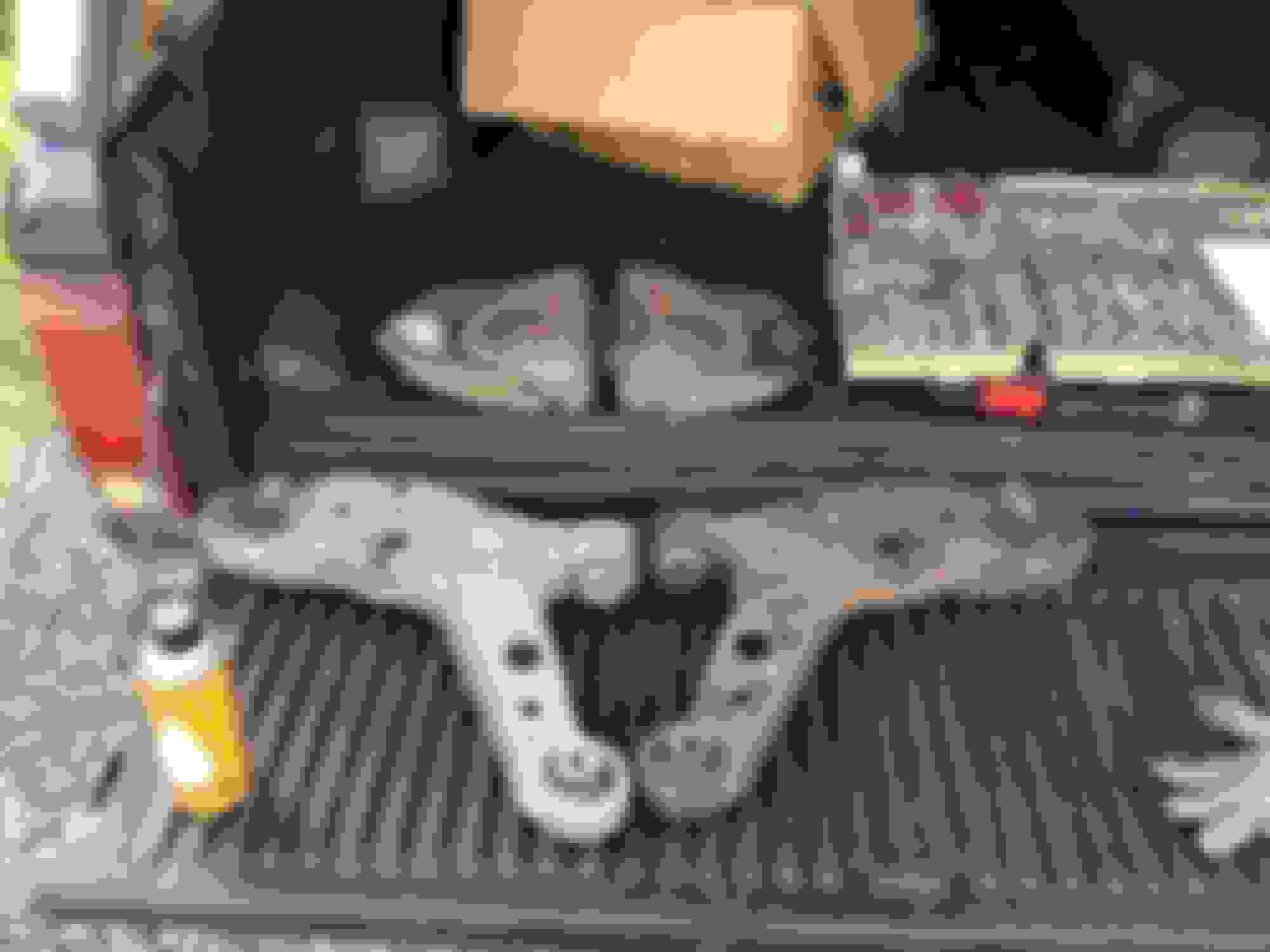
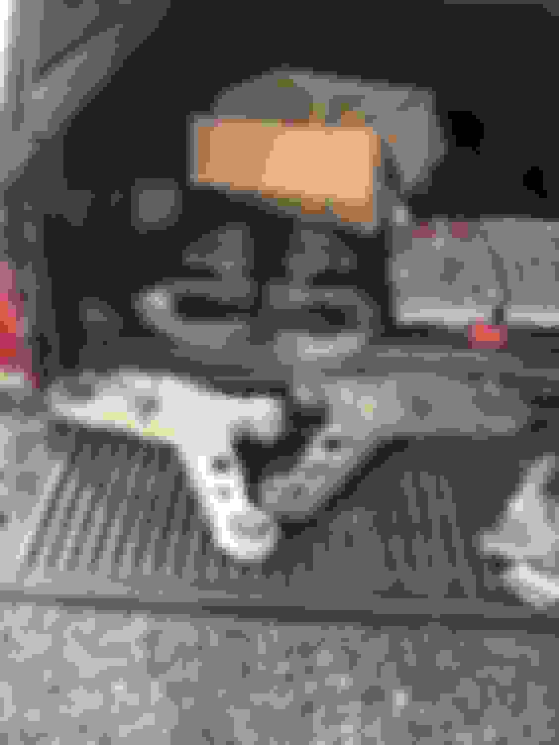
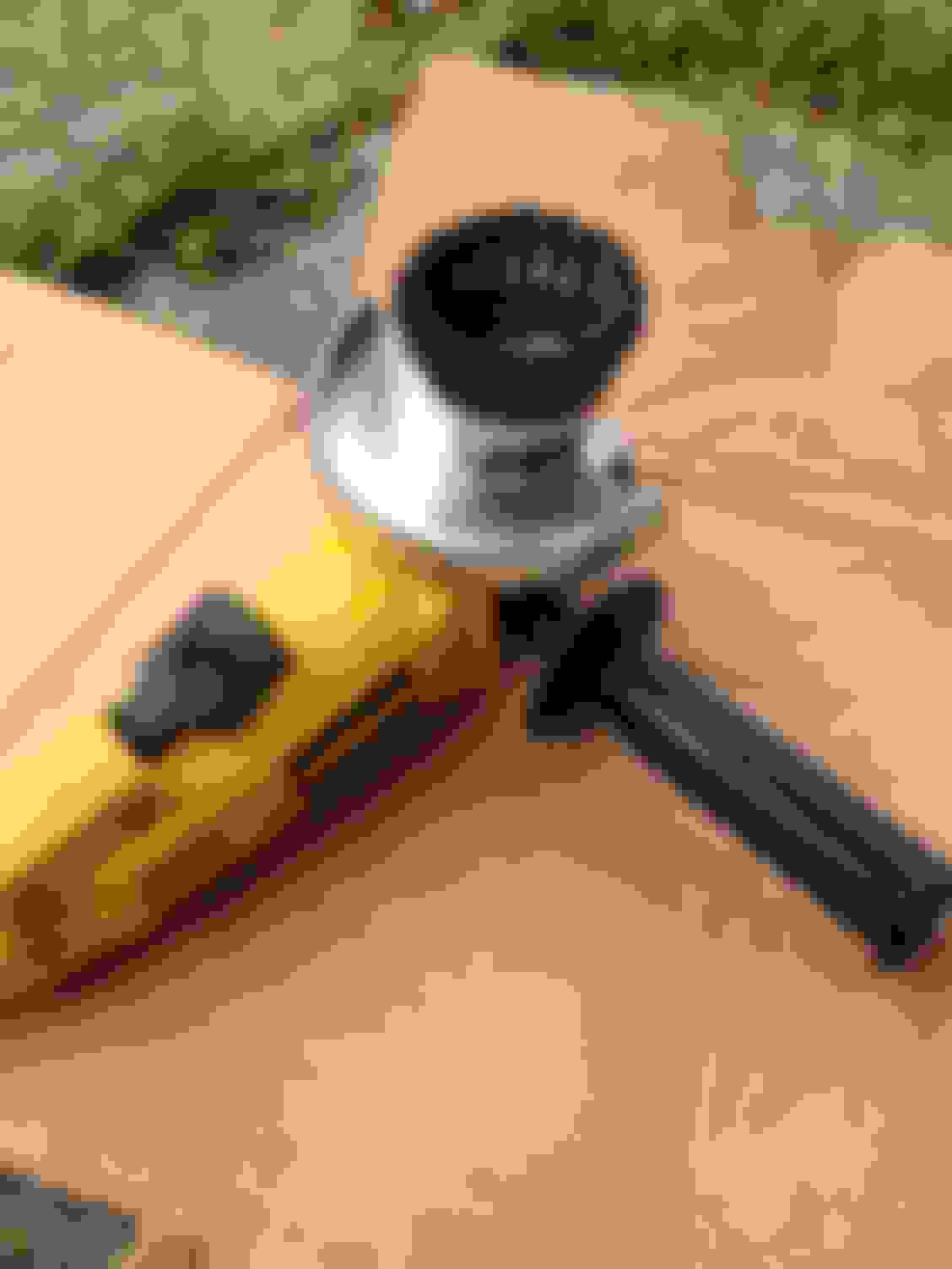
Sorry for the wait guys, been busy with a lot of stuff lately but finally got around to getting to my buddies house after work today to use his H-frame press to work on the lowers. The press was definably needed for the ball joints due to the fact that they didn't fit in the C-clamp with the necessary press and receiver tubes. It wasn't needed for the bushings but sure did help, along with another set of hands.
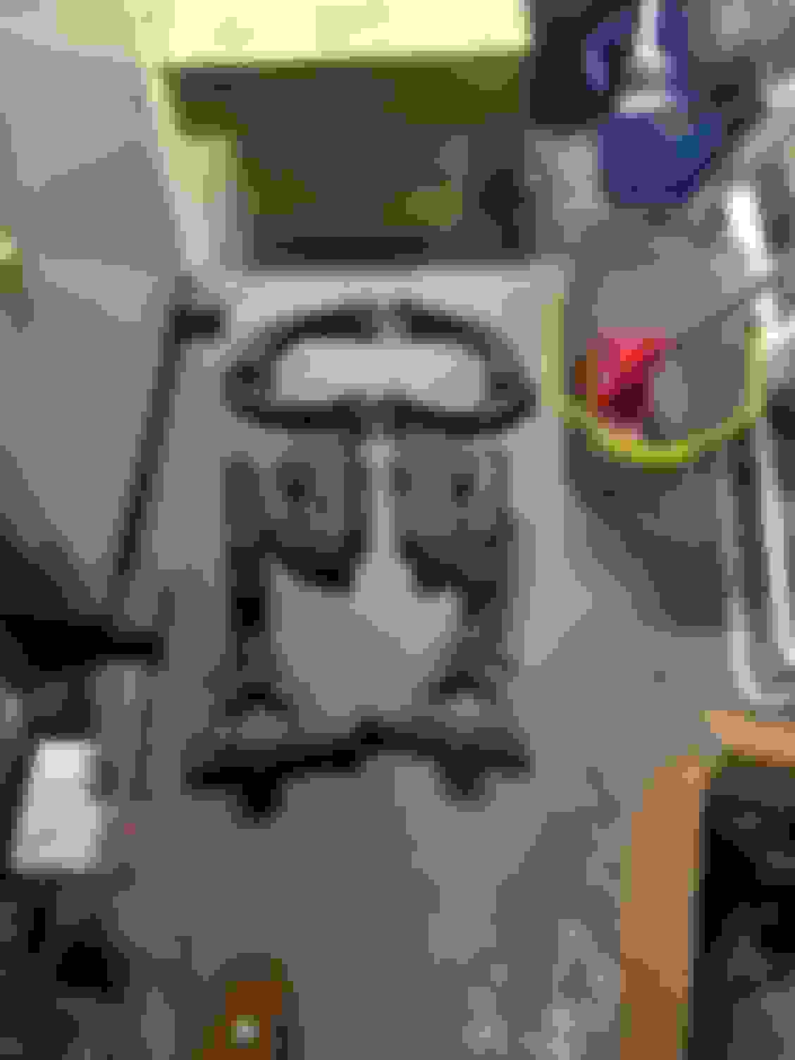
We were moving along pretty fast and I didn't get a chance to take notes on press and receiver sizes, but everything we used came out of the set shown below.
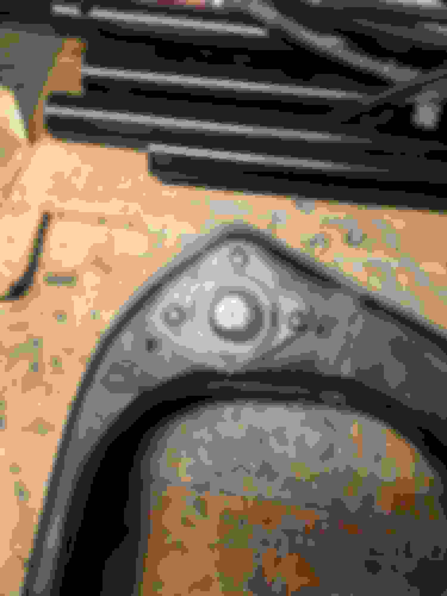
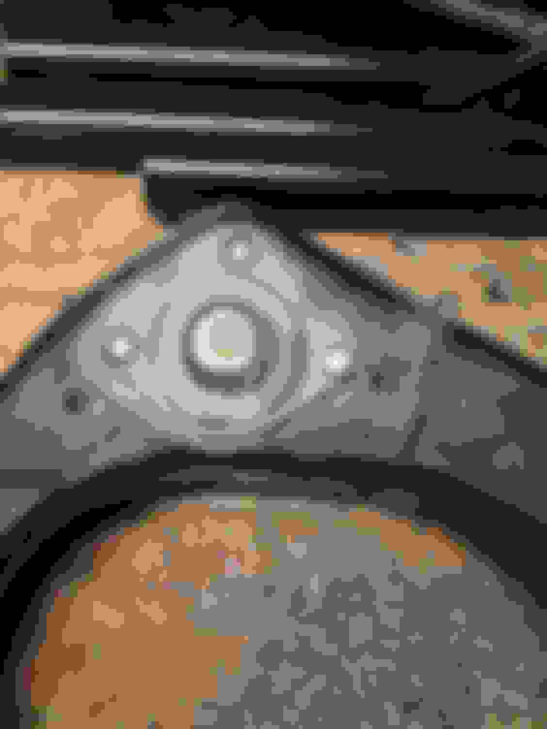
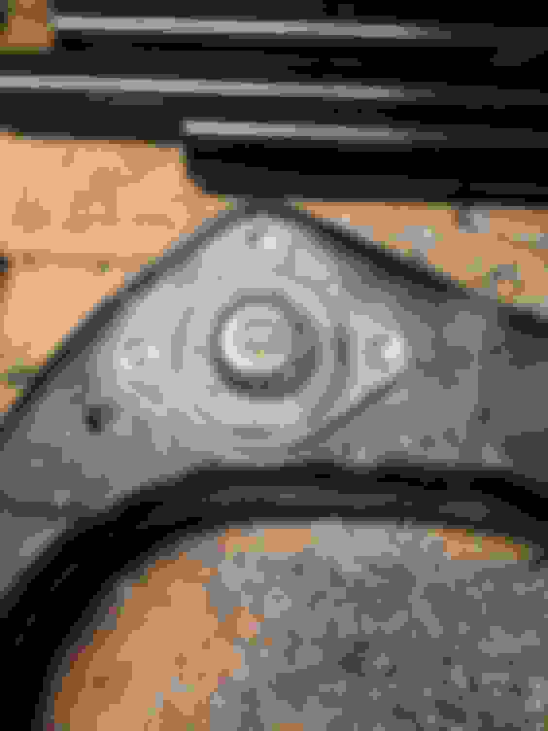
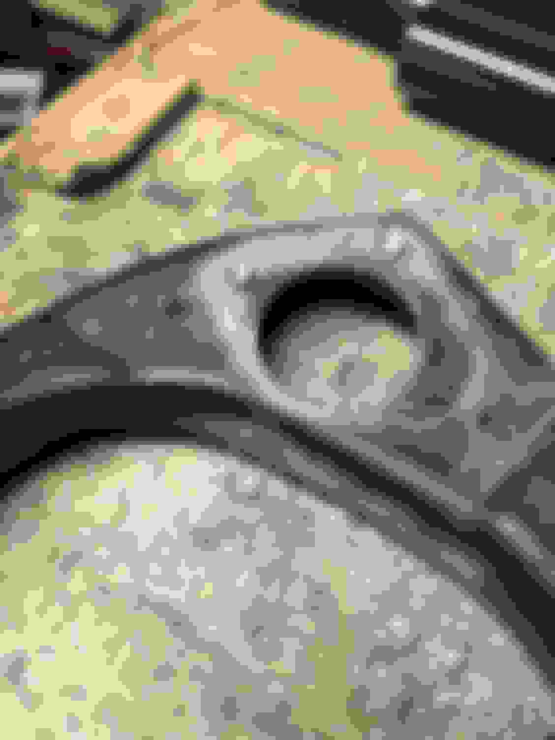
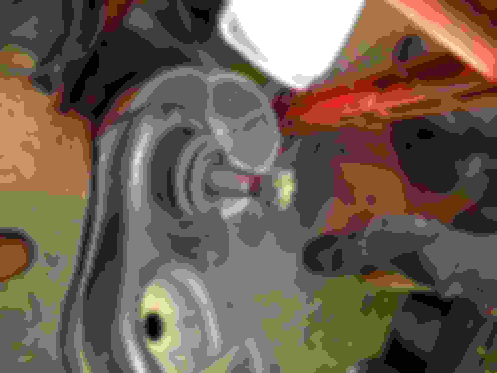
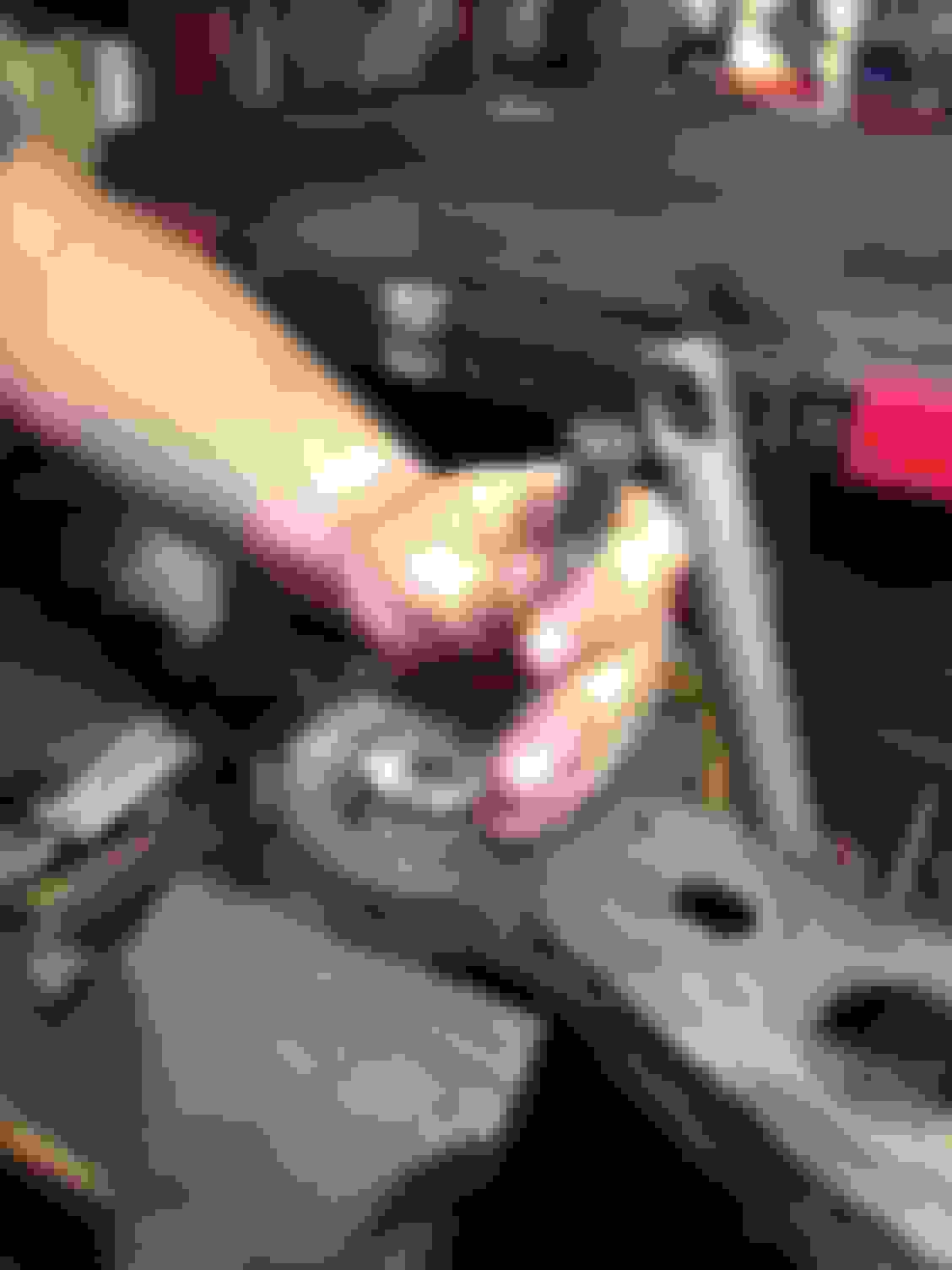
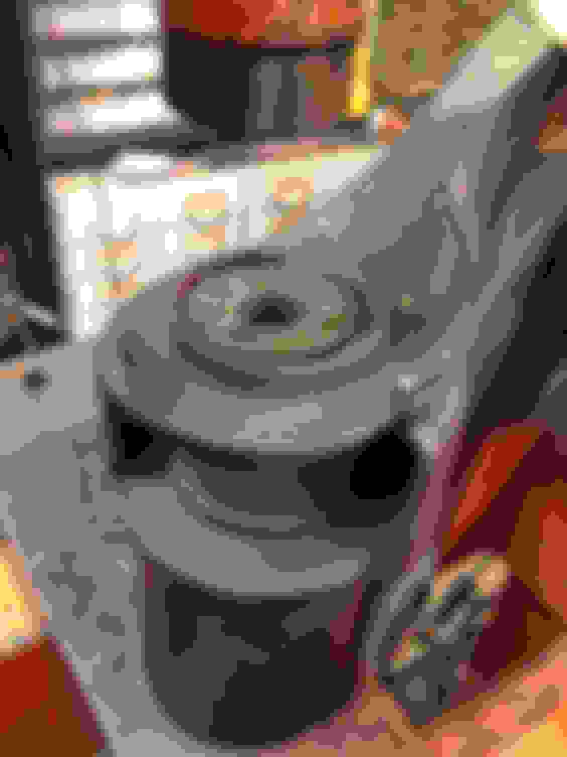
We started off first with the ball joints. They get pressed out towards the bottom. We found a nice size receiving tube that fit good around the bottom lip shown below. I was originally worried that this lip might fold in but it held up good without issue.
We then used a press tube that fit nice on top. You'll destroy the rubber dust boot in the process. I apologize I didn't get too many good photos of the ball joint removal process, but it was the easiest piece to remove from the lower control arm.
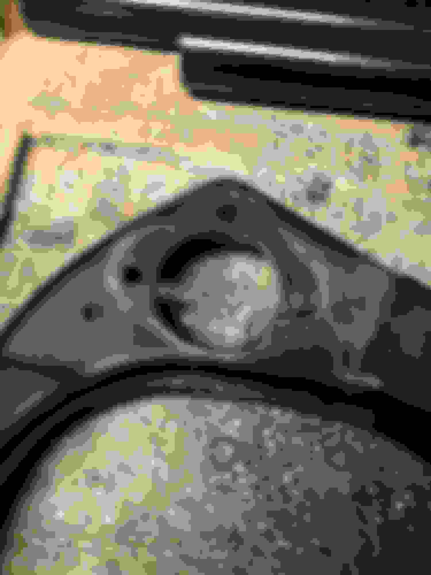
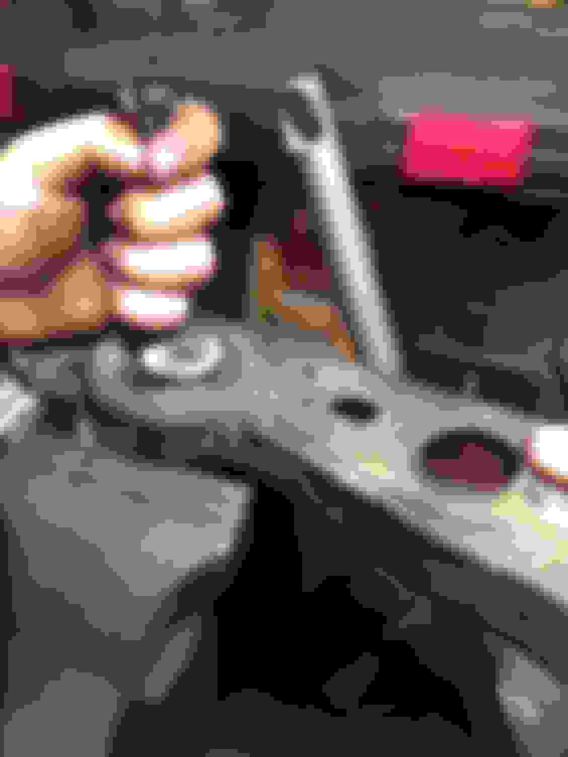
The photo below was after the ball joint popped out, the press tube fell away. The adapter cup was used to press on the press tube.
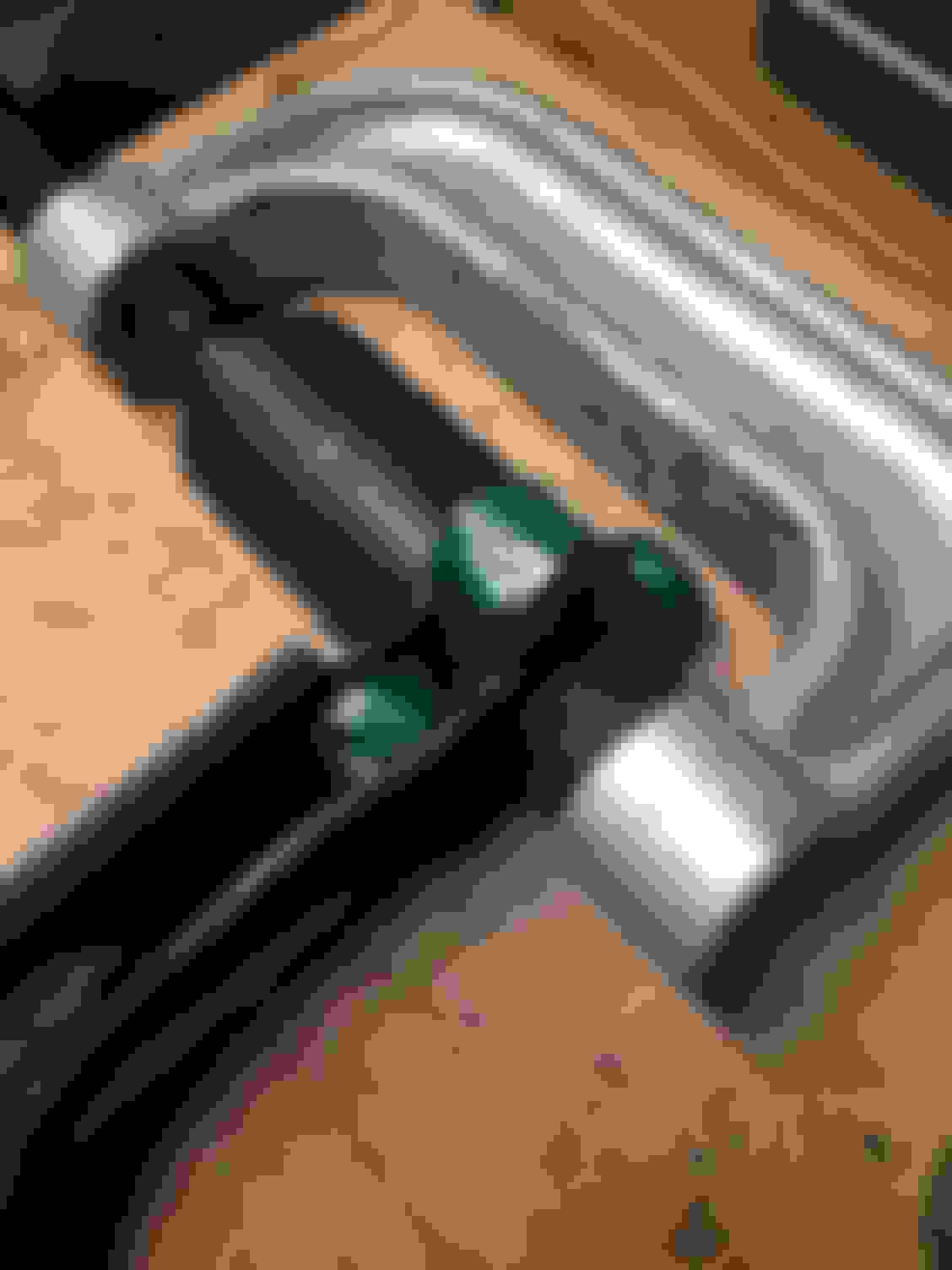
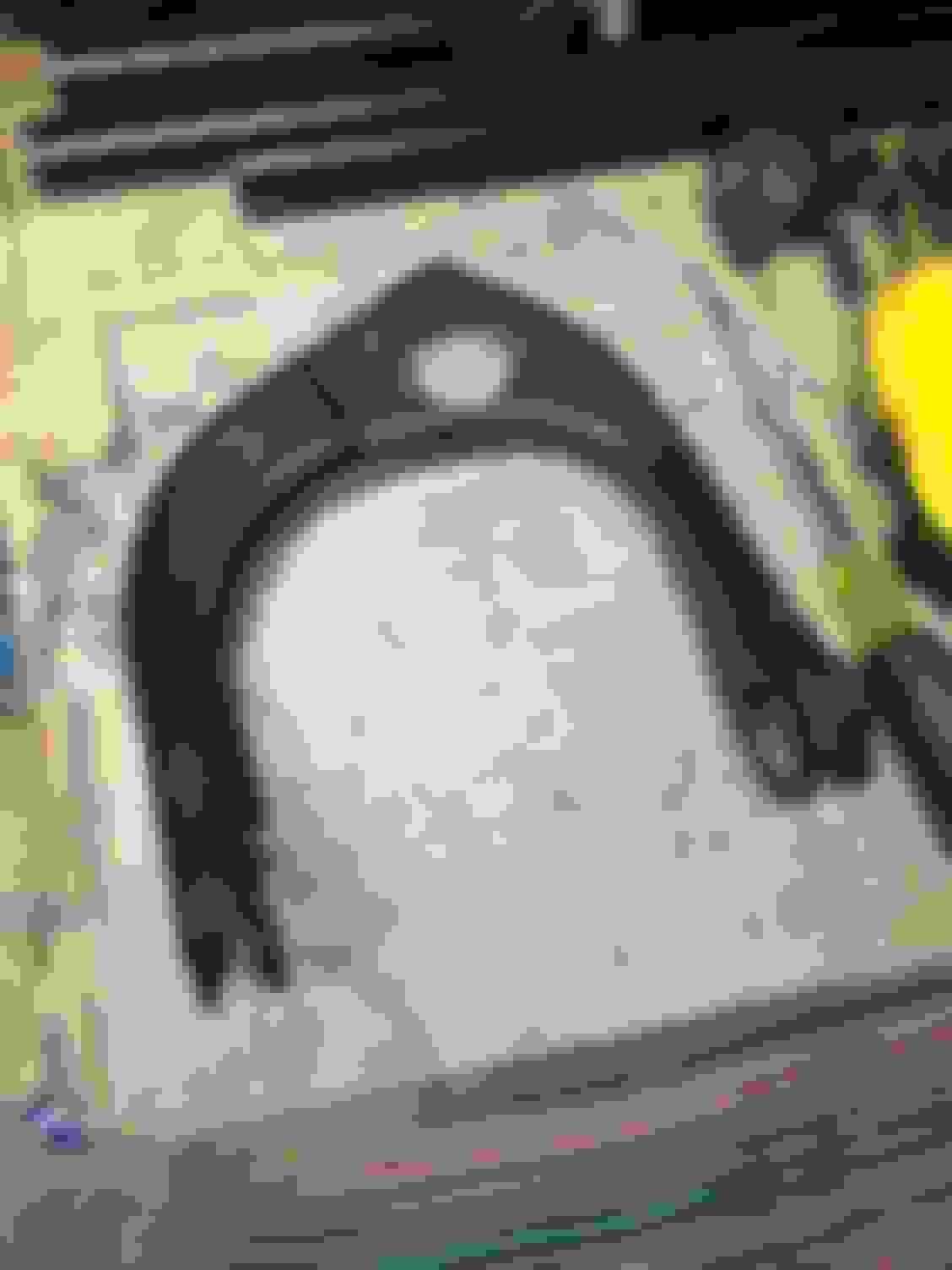
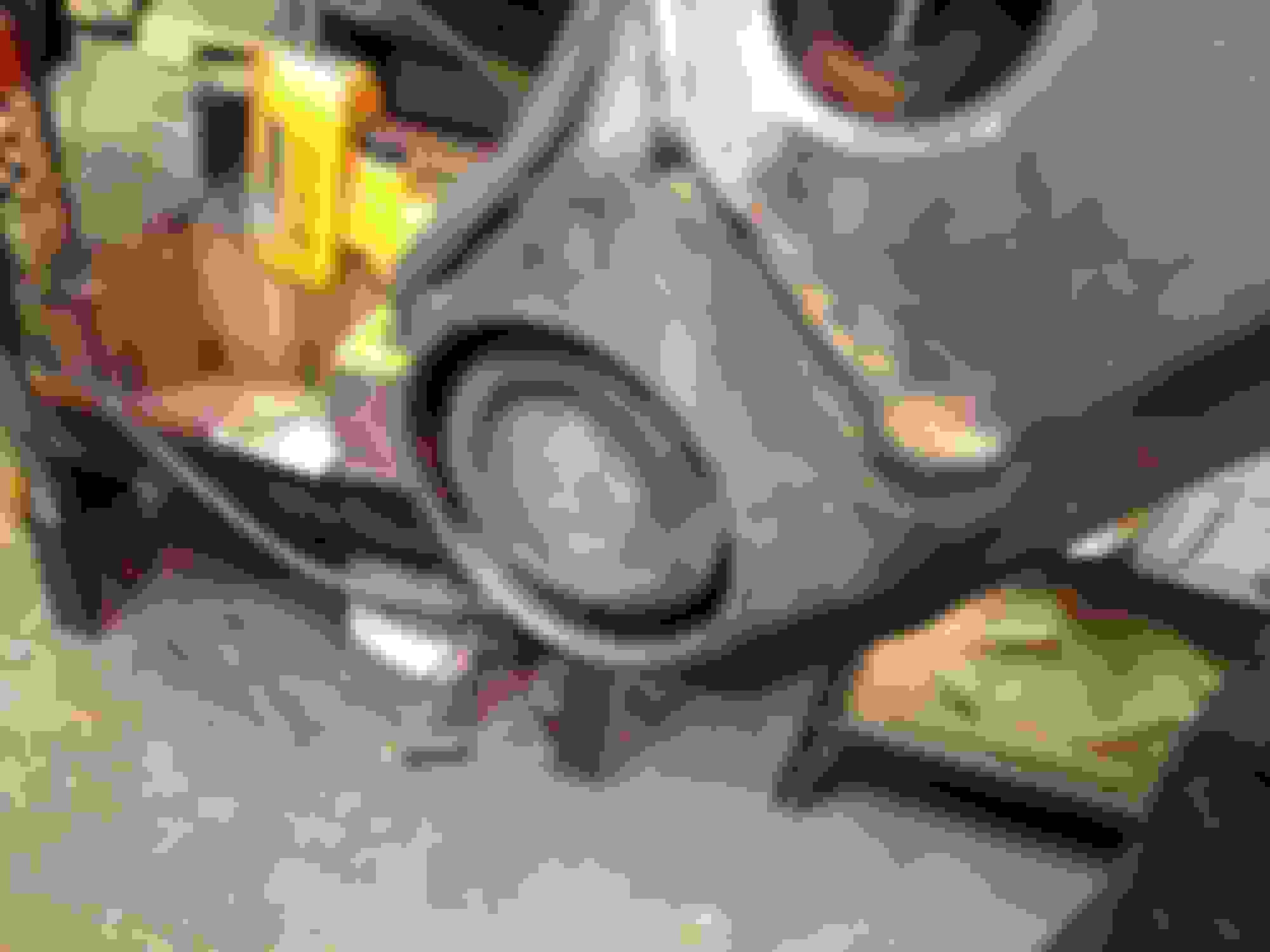
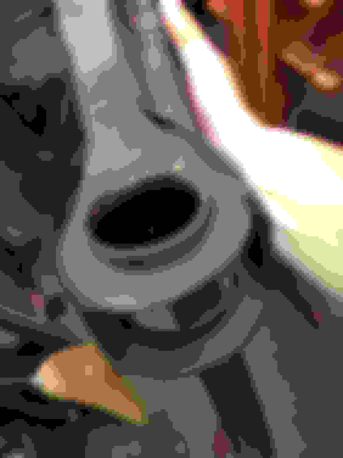
Just like the ball joints, the vertical bushings get pressed out towards the bottom. They were well shot and the outer bushing shells were oblonged/bent, which I though would pose an issue but wasn't that bad as they straitened out while being pressed through the arm. We didn't have a good size receiver or press tube, so we ended up sitting the arm on the press bench and used an adapter cup to press. I thought having the lip of the arm on the edge of the press bench as shown below would bend it but it didn't seem to be an issue. It was definably an area we were watching as we pressed.
The adapter cup does a good job of getting the bushing moving. The first pop is always the big one. We pressed until the cup bottomed out on the arm.
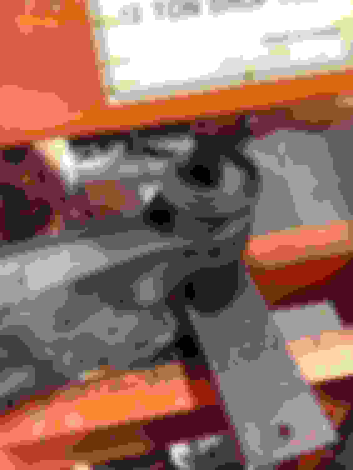
Then it was time to get the old hammer and chisel out. We sat the arm on top of a vice and started working your our around by folding in the outer shell a little. As the edges fold in and you tap around it, it'll start to come out.
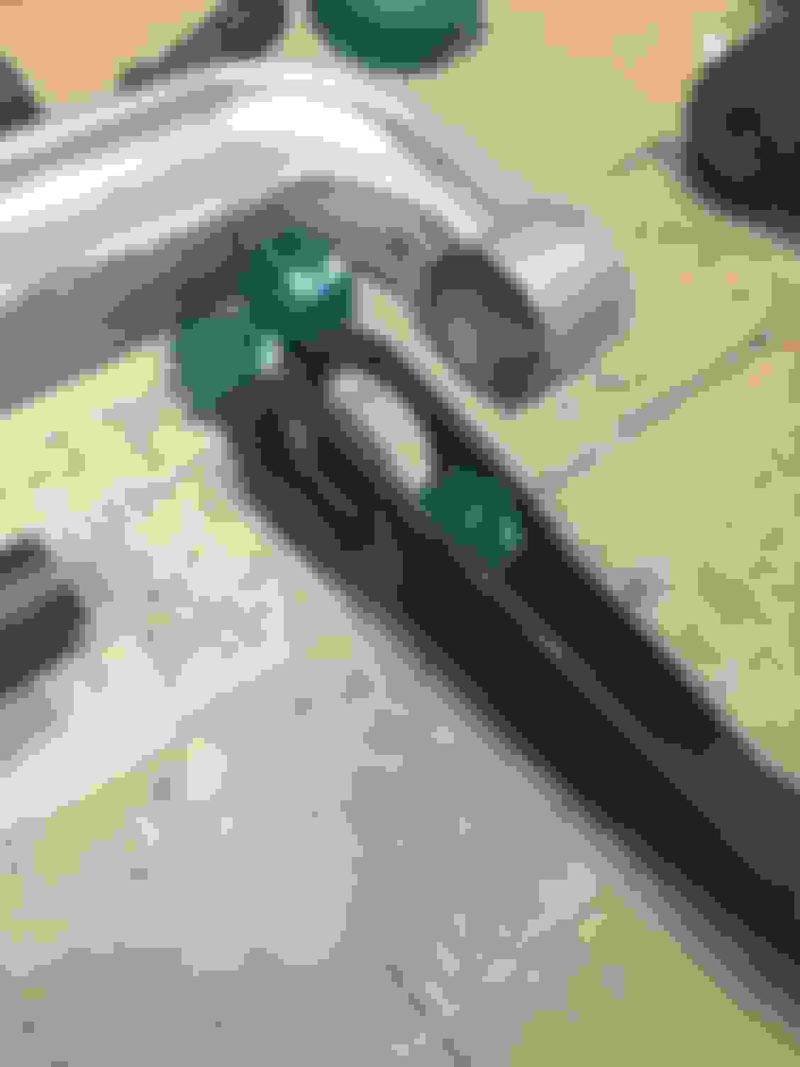
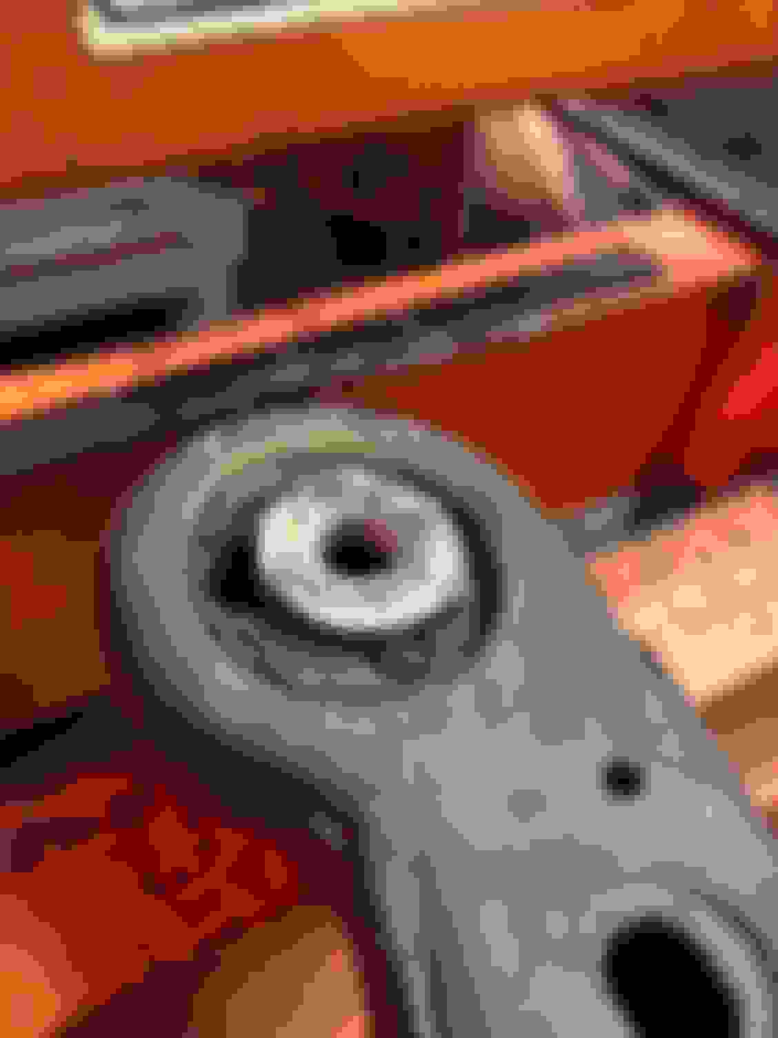
The horizontal bushings were definably the problem child out of the three. The bushing shell lip was just slightly above the lip of the control arm, not allowing much wiggle room with the press. Also, just like the vertical bushing, we had a hard time finding a good press tube size, so we used the adapter cup again. We did end up finding a good size receiver tube.
You don't have much room but with the adapter cup, you should be able to get the bushing to initially pop loose. Don't crank down too much, the cup bottoms out fast and you'll start to bend the arm. Once the bushing initially pops, there shouldn't be much left holding it in. We didn't have a press tube the right size for the bushing, so we pressed on the rubber and got lucky, it ended up popping the rest of the way out without much force. If that doesn't work, I'm sure a hammer and chisel will also work after the initial pop, just like on the vertical bushing.
Lower arms are now ready for paint, which will be next along with the front shock/spring assembly.
Last edited by StoneColdLT1; 05-24-2017 at 08:45 AM.
Started prepping all of the front end parts today. Started by washing everything with some dish detergent to get the big stuff off.
The spindles came off of a northern car and definably show with the rust. I got out of the wire cup and a grinder and started going to work.
What a difference, used a wire brush to get in the hard to reach spots. There was very minor pitting here and there but nothing serious.
The upper control arm mounts were in pretty rough shape as well. As many people know, these rot through a lot of times. These got shipped up with my clean control arms from Texas so it goes to show how easily these will start to rot, even in dry states.
Just like the spindles, I hit these with the wire cup. There's a bit more pitting underneath but nothing structural, just not pretty.
Since the control arms were in good shape, I was initially not going to take the wire cup to them. However, I decided to hit them real fast and it was a good choice. It took off surface rust and loose paint that looked good. Phone was dead and I was trying to get that done so unfortunately, no before and after of the arms.
Last edited by StoneColdLT1; 06-02-2017 at 09:25 AM.
Was able to get the upper and lower control arms painted before the end of the day.
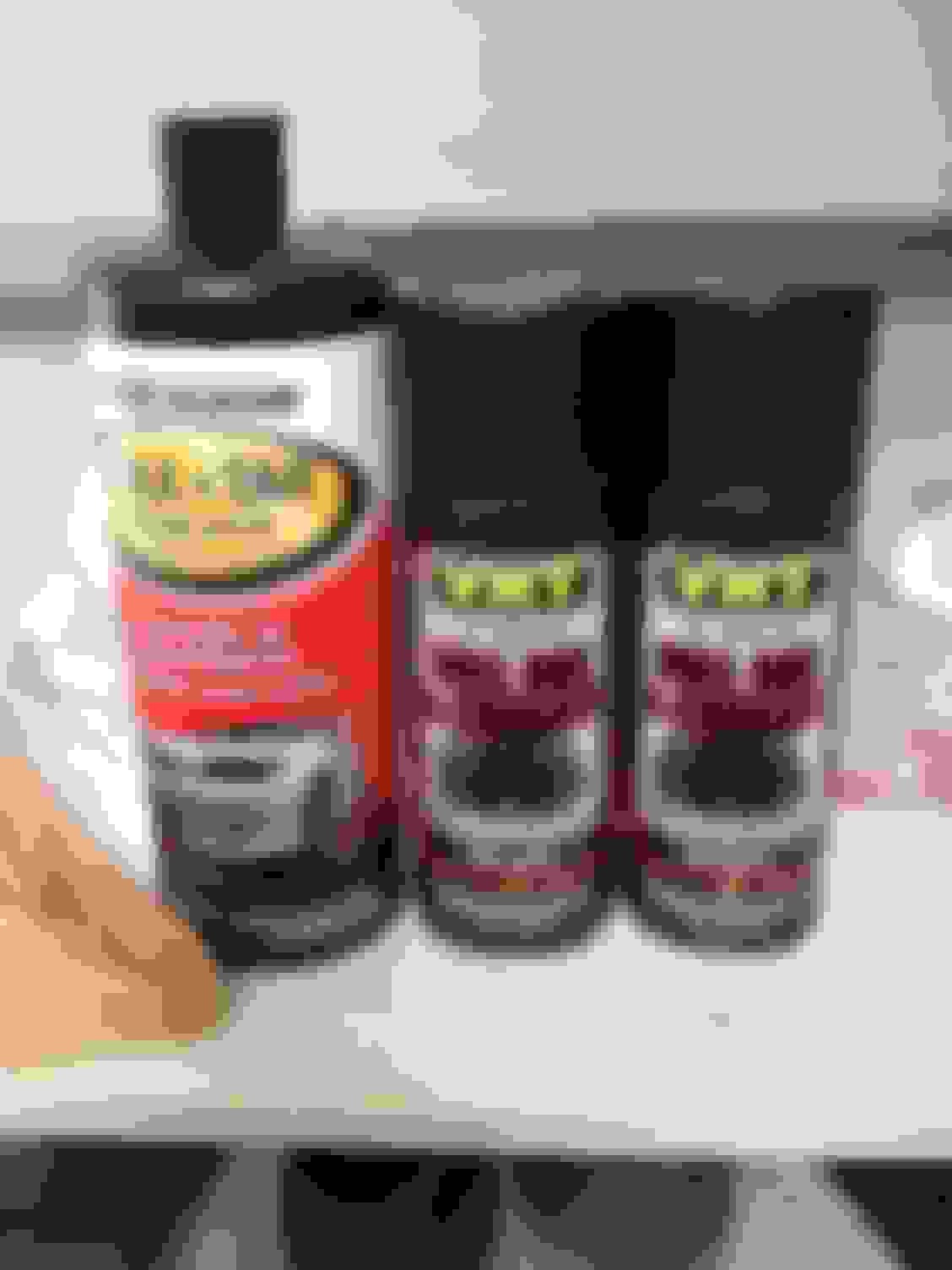
I ended up using VHT Roll Bar & Chassis paint in gloss black, which is a one-step epoxy coating. I usually like a primer and paint separate, but I've heard good things so I decided to give it a try. I'll probably also use it to do some touch up underneath the car as well.
Following VHT's instructions, I wiped the arms down with wax and tar remover and sanded them using 320 grit. I then hung them and gave them another final wipe-down with the wax and tar remover, waited for it to dry and started spraying.
This is after the first coat of paint.
Did a total of three coats. They are currently hanging in my basement to cure overnight and are looking pretty good. Hoping to paint the spindles and shock mounts tomorrow.
I just replaced a lot of my suspension. I did not change my top mount or spindle. I don't know if you have used POR-15 before, but the stuff is amazing. It can be painted directly over surface rust and it won't rust again.
The other thing. You likely know this, but the 5th gen rotors have a different size pilot hole you will need to enlarge that for the 4th gen bearing.
Good luck I was not willing to change my bushings... I just bought new control arms. Well besides I wanted for camber and caster.
Honestly I'm not a big fan of POR-15. I know a lot of people swear by it but I've witnessed it flake off a rear my buddy had which was prepped correctly which makes me think it doesn't cure well to clean prepped metal. Also, I wanted to use something I can pick up locally in a store. That way I can easily pick some up for touch up.
I plan on getting them opened up at the machine shop this week.
I'll eventually go tubular adjustable down the road, but I spent so much money on everything else, I decided to rebuild the stocks for right now just to save on some cash.
I'm not a POR-15 sales person... but I think it wasn't prepped right if it flaked. You need to etch bare metal for it to stick, they sell a product called metal ready to do this. I painted my 9" over 10 years ago and it is still perfect. And I didn't top coat it. That was bare metal. I also wire brushed those top mounts and there was some really slippery bare metal and with prep it was fine. It also works extremely well on skin and garage floors
Anyway, I keep a can of the stuff on hand all the time. But, to each their own. I see a lot of companies copying it now. Just offering an alternative since it is impossible without media blasting to get all the rust off.
You're probably right, to be honest I think most stuff works when properly prepped and applied. I also expect that no matter what you use, it's going to get chipped up when actually used and driven on the road. As long as this stuff doesn't flake off I'm fine with it. We'll see how it holds up. Maybe I'll try some POR-15 on something else.
OP, you've done an excellent job. POR-15 I've found really needs a top coat, it fades out, and as stated with out etching the metal will flake. I used rust bullet for undercoating, had I not done powdercoating, I'd have used rust bullet on the suspension also.
Got around to painting the spindles and UCA mounts today after work. Same paint and process at the arms. VHT Roll Bar & Chassis in gloss black, hit with 320 grit and some wax and tar remover. I also hit them with the wire cup as they flash rusted a little in my basement over the week, they actually came out looking cleaner than they did the first time.
After three coats.
The front end of the car might start coming apart tomorrow after work. I also just got in another set of rear lower control arms so I can prep and paint as I did the fronts. I also need to prep and paint my relocation brackets and panhard bar for the rear.
Last edited by StoneColdLT1; 06-02-2017 at 09:25 AM.
Got home from work tonight and I was able to start tearing down the car. Didn't get much done though.
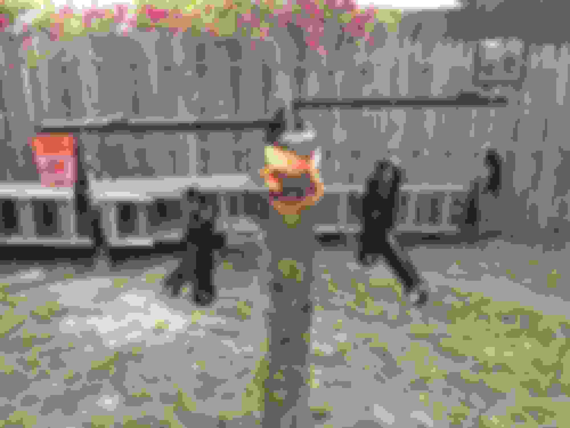
First, I pulled it out to take some official "before" photos to compare with when done.
Then it was time to jack it up
First thing I did was removed the fender liners. You need to at least move a portion out of the way on the driver side to get the sway bar off but removing them completely isn't necessary. I'm going to clean up and paint underneath there so that's why I did it.
The liners are held in by (3) push clips, (2) 10mm bolts, and (4) 7mm bolts.
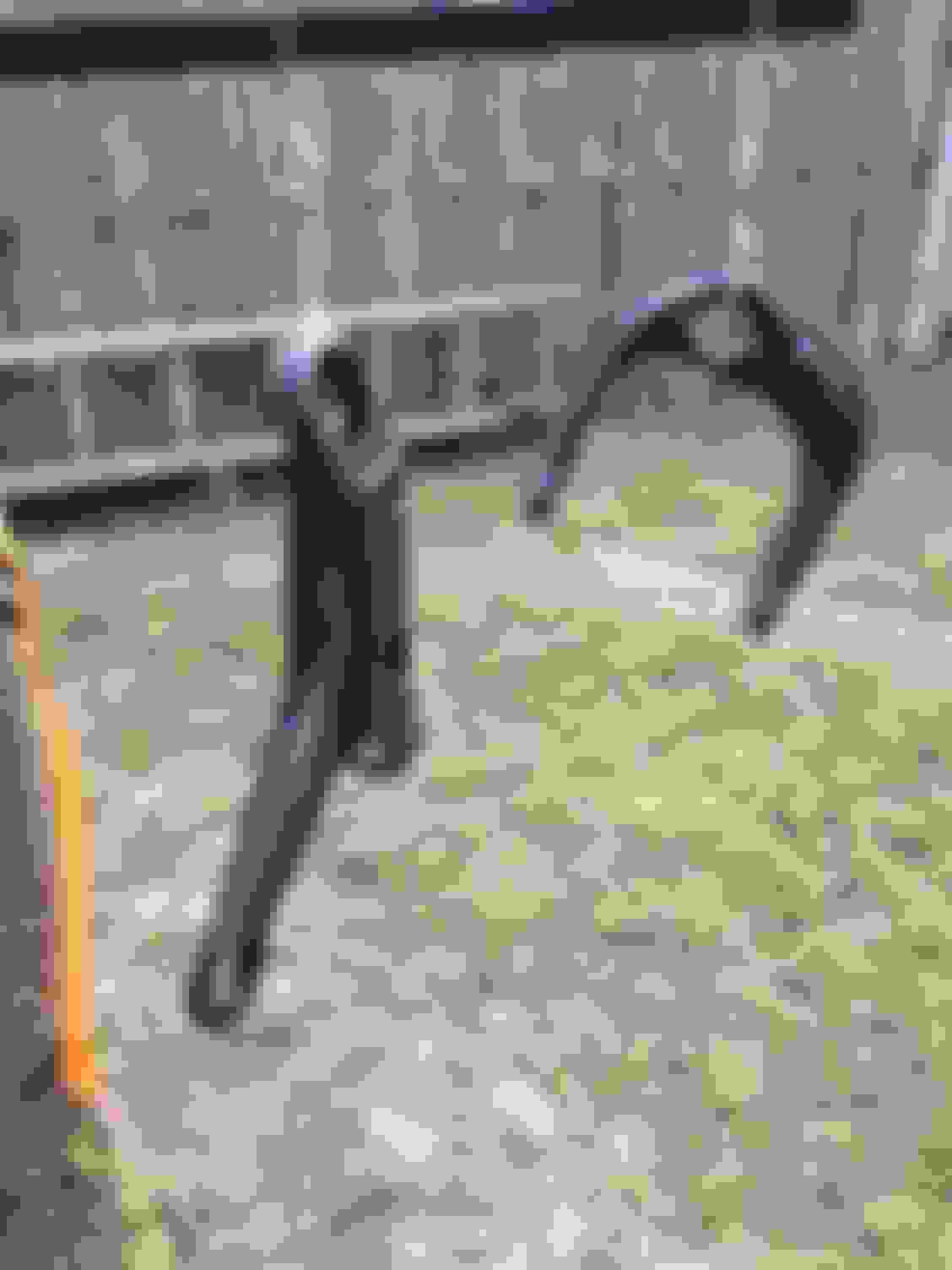
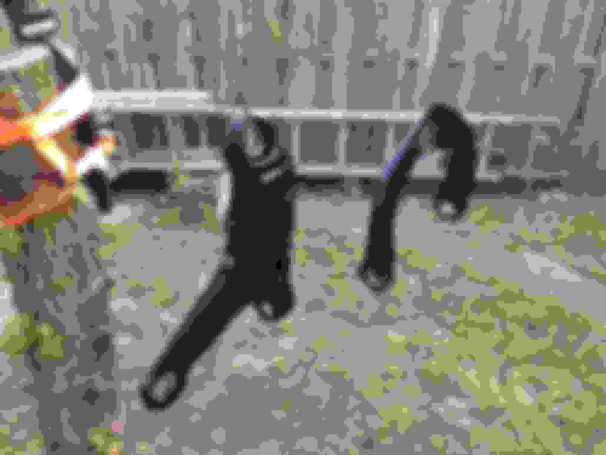
Up next was the sway bar end links. These were very rusty. There's a 13mm bolt on the bottom and 13mm nut on top. I put a wrench up top and wedged it against the shock as I cranked on the bottom. It took a bit of cranking and did generate some heat, penetrating fluid helps. I would have used an impact but it was getting dark and didn't want to **** off the neighbors. This is the same on both sides.
Once the top bushing/nut is off on both sides, the sway bar can be rotated up and off the link. The middle bushings slide off and the rest slides out of the bottom of the control arm.
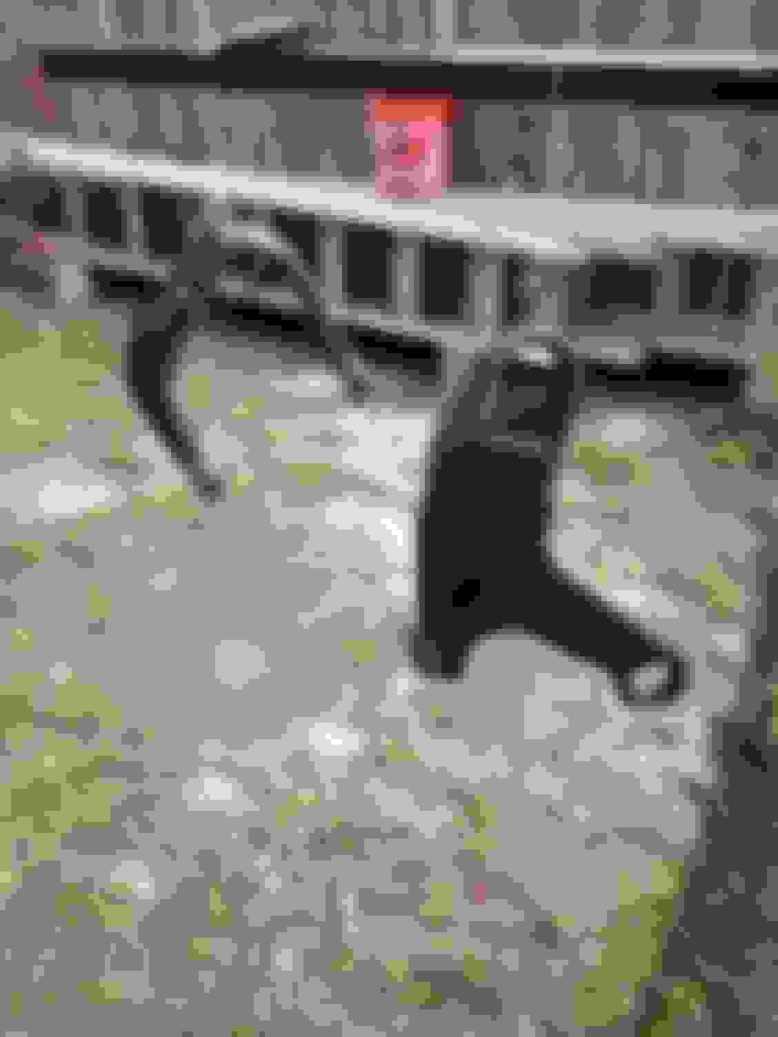
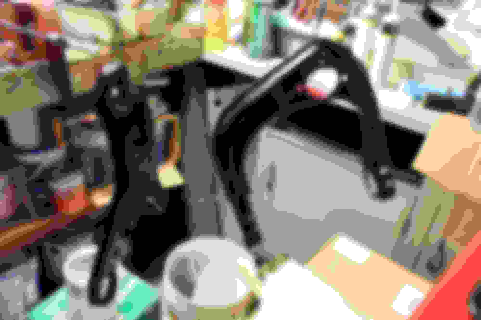
Next was the mounts to the body. The passenger side is business as usual when it comes to sway bars, (2) 13mm bolts and it's off. Don't take the bolts all the way off until you get the driver side.
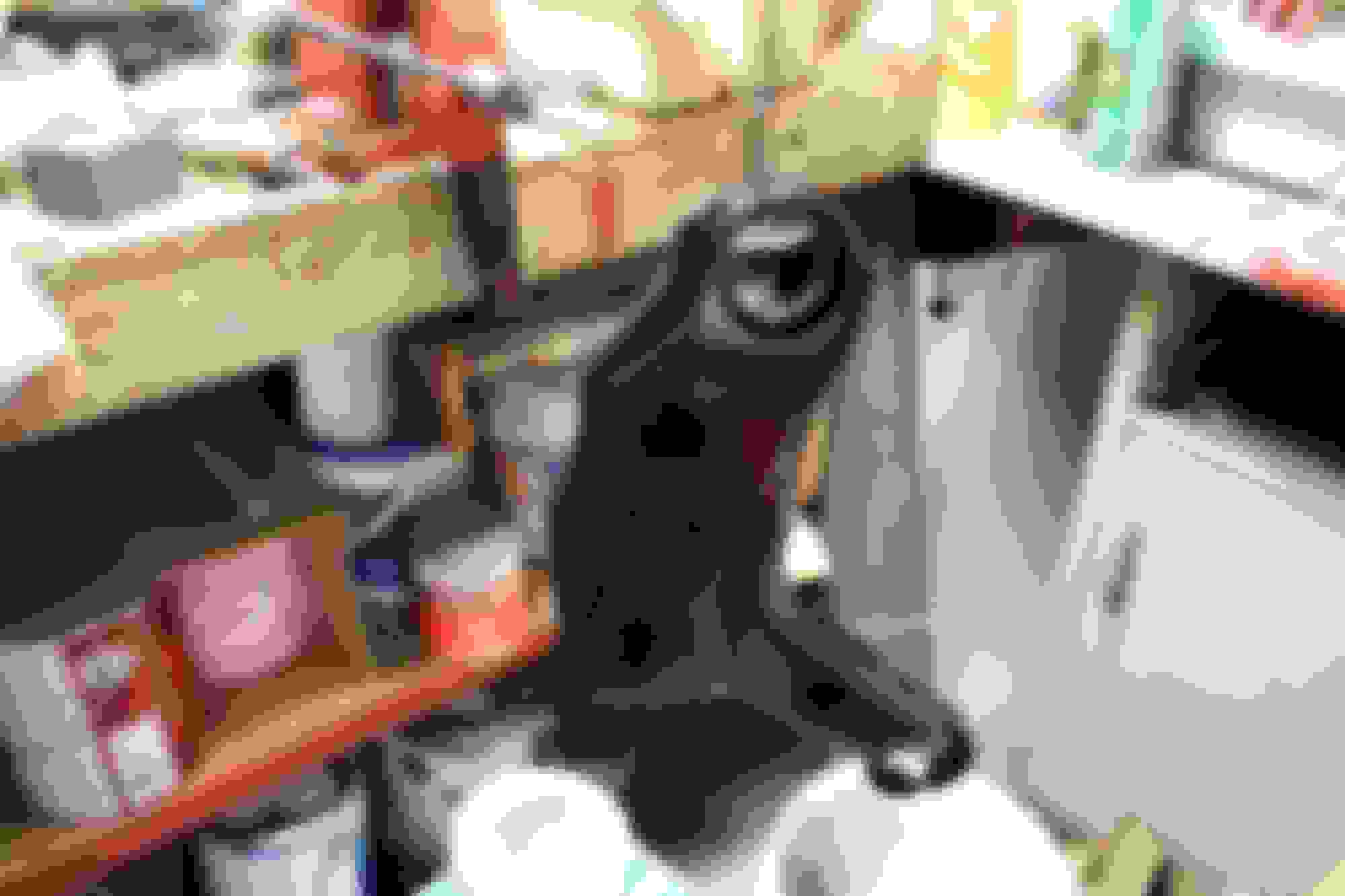
The driver sides has a 13mm bolt and a 13mm nut on a stud. Loosen the bolt and remove the nut. There is a plate that sits over top of the sway bar mount that needs to be removed. In addition to the 13mm nut, there are (2) 10mm bolts that need to be removed, one is hidden behind the splash shield.
Crappy pic but here is one of the 10mm bolts that hold on that plate. The hidden one is to the left of it behind the splash shield.
Once the plate is removed, there is another 13mm studded bolt. This is what is holding in sway bar. Remove that with the three other bolts and it falls right out.
That was pretty much it for tonight. Before calling it a night, I hit all of the joints with penetrating fluid to get them ready for a long day tomorrow.
Last edited by StoneColdLT1; 06-03-2017 at 09:18 PM.

 04-24-2017, 10:29 PM