When you click on links to various merchants on this site and make a purchase, this can result in this site earning a commission. Affiliate programs and affiliations include, but are not limited to, the eBay Partner Network.
It's generally of high quality, has a bunch of layers which I've never had any issue with, and most importantly all their stuff can be got in 100% logo-less black silicone!
Awesomeness! I love both of your builds. This one, and your 2nd gen on Expo forums. You have talent good sir, and you put it to use, which is better still. Keep up the good work!
Awesomeness! I love both of your builds. This one, and your 2nd gen on Expo forums. You have talent good sir, and you put it to use, which is better still. Keep up the good work!
Thanks! The truck thread is about the same level of detail, but the projects are much smaller since that thing has to be a daily driver
Originally Posted by Jimbo1367
Frojoe,
Did you hear of anyone using the cf? What will be your method of sealing jts? Thanks for the link.
Jim
I haven't personally read of anyone trying pre-made carbon tubes for charge piping, so it'll be an interesting experiment. I'll attempt this carbon stuff using a two part epoxy from a company called Araldite, we use it often at work for joining aluminum-aluminum, aluminum-carbon, and carbon-carbon. I'll make and glue in a thin internal sleeve that extends maybe 2 inches into the carbon ID.
What about moving the alternator to where your PS pump is and converting your hydraulic PS system to electric? There is a guy who did this for a falcon on this site and I have to say it's got me intrigued especially since I have to buy a new Saginaw box anyways. This might free up some room for your piping and turbo's?
What about moving the alternator to where your PS pump is and converting your hydraulic PS system to electric? There is a guy who did this for a falcon on this site and I have to say it's got me intrigued especially since I have to buy a new Saginaw box anyways. This might free up some room for your piping and turbo's?
That's an interesting idea. I've researched EPS on and off over the years more as a curiosity, I think there was a Saturn variety of a EPS unit that was liked by the few guys out there that have attempted home-brewed setups. I'm sure I could engineer an Arduino program to control the EPS unit with a VSS input from the Holly Dominator.
Couple things to consider.. going to an EPS setup still requires a manual box on the framerail, so that wouldn't gain me too much extra room for the downpipe. It would also require room under the dash that simply doesn't exist on my car.
I've dialled my bump steer, so it would be a shame to ditch the box-and-link setup and go to rack and pinion (not to mention a $$$ custom rack end links). That being said I do eventually want to replace the existing box with a Lee box or something like that, as my road feel and return-to-center is okay-ish but could be better. Swapping from the Saginaw truck pump to a GM Type II pump did reduce flow/pressure and increase feel.
There are OEM brackets to fit the alternator low driver side, which is an incentive.. but since it looks like I can physically fit the alternator on low passenger side if I just make my own bracket, that seems to be the easiest and lowest $$ solution since everything else can remain the same.
I have an idea for a some oval 3.5" for the diver side downpipe giving some more clearance to the upper control arm cross-shaft and box, with a heatshield around the steering box and some rerouted power steering lines. I'm still leaving my options open for when I get closer to the point of routing the downpipe.
Mockups = progress. Getting the alternator low is great. Given the truck PS is already low, I'm surprised you can fit both - good deal! On mine I did notch the frame for extra room around the alternator even thought it might have fit. I'm glad I did because it provides room to maneuver the alternator around the power steering during install, gives hand access to the output/charge post, and provides some air space around the alternator.
With regard to the pipe-to-flange fitment, do you plan to weld inside and outside, then grind to make the transition / port match? I would suggest something along those lines. It'd be nice if you could form the end of the elbow to transition even more smoothly; maybe you could squish it down a bit in a press tool/form to make it even more better.
Also you aren't the first person to have failed welds on custom exhaust piping. Not that uncommon and especially tough to avoid on both thick and thin materials for different reasons. Not necessarily a test on your fabrication capabilities. Avoiding welds is one of the reasons OEMs cast their exhaust manifolds. If you were really cool you'd fabricate your exhaust manifolds as plugs then sand cast them.
I've seen a guy over on SNS who hacked up the front subframe to add rack & pinion. I for one don't feel comfortable with that mod as the stock subframe was hacked up pretty good, while I give the guy credit for doing it I think going with a aftermarket subframe would be better all around.
Here is the thread that waid786 did on this site for converting to EPS using sytems other than the saturn. The prius seemed to be the easiest and was able to work without VSS or a 3rd party module. For as little as it costs at a junk yard I may grab one and see how much fab it takes to fit it on the column and under dash space.
Mockups = progress. Getting the alternator low is great. Given the truck PS is already low, I'm surprised you can fit both - good deal! On mine I did notch the frame for extra room around the alternator even thought it might have fit. I'm glad I did because it provides room to maneuver the alternator around the power steering during install, gives hand access to the output/charge post, and provides some air space around the alternator.
With regard to the pipe-to-flange fitment, do you plan to weld inside and outside, then grind to make the transition / port match? I would suggest something along those lines. It'd be nice if you could form the end of the elbow to transition even more smoothly; maybe you could squish it down a bit in a press tool/form to make it even more better.
Also you aren't the first person to have failed welds on custom exhaust piping. Not that uncommon and especially tough to avoid on both thick and thin materials for different reasons. Not necessarily a test on your fabrication capabilities. Avoiding welds is one of the reasons OEMs cast their exhaust manifolds. If you were really cool you'd fabricate your exhaust manifolds as plugs then sand cast them.
I'm super stoked on low mounting the alternator. I think I'll still give the subrame a minor notch to allow installation and plug access room to the alternator. After spending several hours looking at other alternator options I really can't find any alternatives that are smaller in OD or slimmer, or even have the stud and plug in a better orientation on the alternator. I've read that the LS2 Corvette alternator is "slimmer", but can't find any dimensions and don't really want to spend a couple hundred bucks when I can just cut up the subframe and reuse the alternator I already have that still works.
I do plan to weld inside and outside the pipe at the flange. Outside fillet weld will be the big multi-pass strength weld, the inside weld will be to fill/smooth and transition better. Even at 1/2" thick, I'll probably face mill the flanges after welding just to ensure a flat gasket surface. I will still try to squish the pipe, but at 0.210" wall I'm not holding my breath even with the pneumatic press at work.
Don't tempt me to make my own molds (I do however have grand ideas about my own carbon hood and trunk lid)! The risk of weld failure after heat cycling is the main reason I'm trying to keep the pipe lengths and welds to a minimum, and the wall thickness up. Even though technically SS304 isn't the right material for this high heat turbo application, it's hard to argue with all the apparent success online (as well as on Mark's build) of SS304 as turbo piping, as long as the wall thickness is significant.
Originally Posted by cap42
I've seen a guy over on SNS who hacked up the front subframe to add rack & pinion. I for one don't feel comfortable with that mod as the stock subframe was hacked up pretty good, while I give the guy credit for doing it I think going with a aftermarket subframe would be better all around.
Here is the thread that waid786 did on this site for converting to EPS using sytems other than the saturn. The prius seemed to be the easiest and was able to work without VSS or a 3rd party module. For as little as it costs at a junk yard I may grab one and see how much fab it takes to fit it on the column and under dash space.
That's some cool info, thanks for the thread link... I'll flip thru it. I'm still super intrigued by the idea of EPS, and that's not ruled out as a future mod, I just don't want to dive into it now and have it as another critical path to hash out and get working before I can start driving this thing again. But it is a really cool idea to have speed-sensitive steering feel.
I have been thinking about moving the hacked up factory fuse block which I put under the steering column and relocating it to the passenger footwell area, where the heater box currently is (but will be removed soon). This could free up some room for the EPS unit next to the column under the gauges.
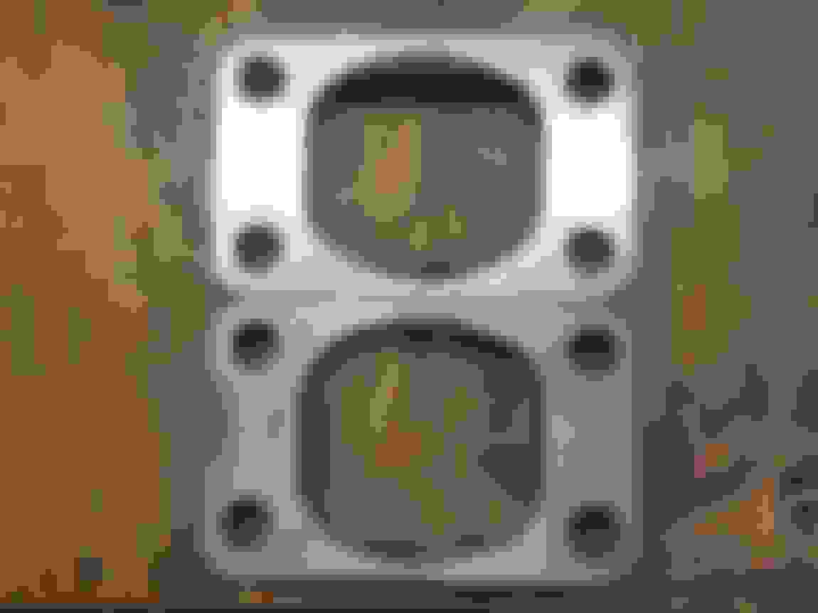
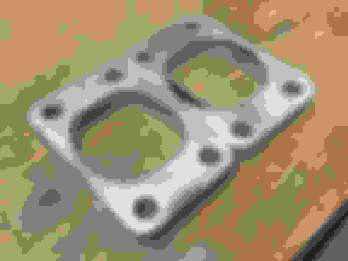
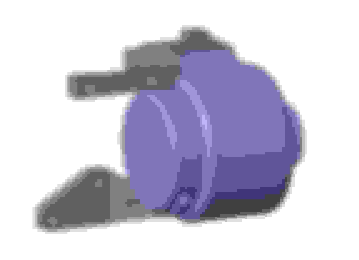
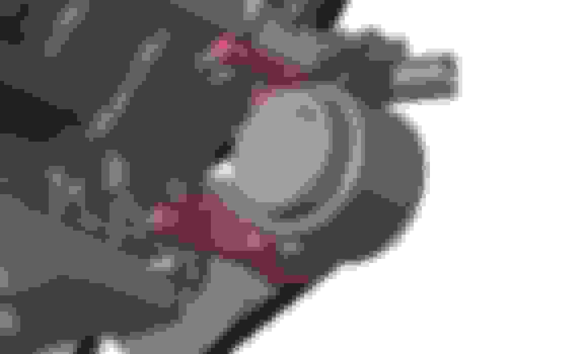
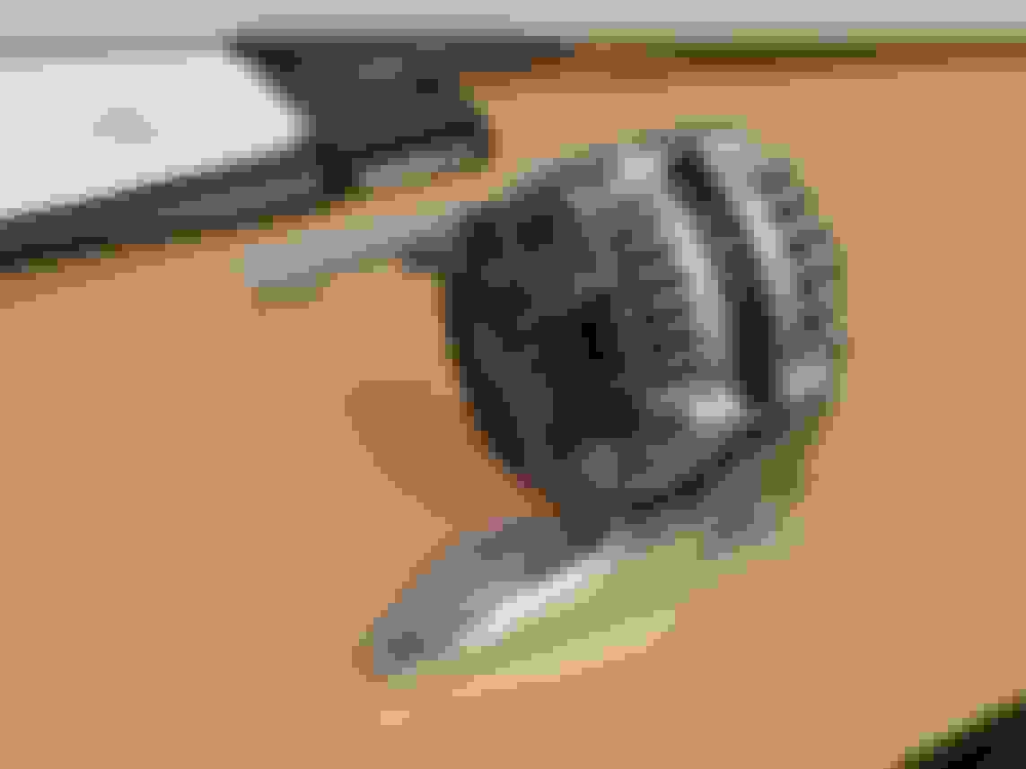
It was pretty easy to do some manual porting of the T3 flanges, took about 15 minutes a piece having the big shop compressor running flat out with the belt sander and a couple 40 grit belts.
Received another order of stainless which should round out the raw materials I need for plumbing to the turbos, then turbos down to firewall (including wastegates). Man the 16ga piping is nice stuff.. hope my welds end up being good enough to do the material justice.
Also grabbed some SS304 CTS-V exhaust flanges off a CNC exhaust flanges maker on eBay, they see good quality and fit well. I like the widespread bolt pattern for supporting the cantilevered weight of the turbos and piping, versus the added annoyance of welding v-band flanges onto the manifolds again.
Also grabbed this Spectre tight radius intake elbow to maybe gain a couple inches of room to the rad support. Not sure if I'll use it, but an interesting option to try that I'll have to confirm the need of when I start modifying the inner fenders.
Finally stripped the engine bay of everything old turbo setup, and all the wiring and everything essentially forward of the tires.
An idea I'm playing with is sealing off the area behind the headlights and corner lights from the engine bay heat, and having ducts from under the bumper direct air up into the air filter area located behind the headlight.
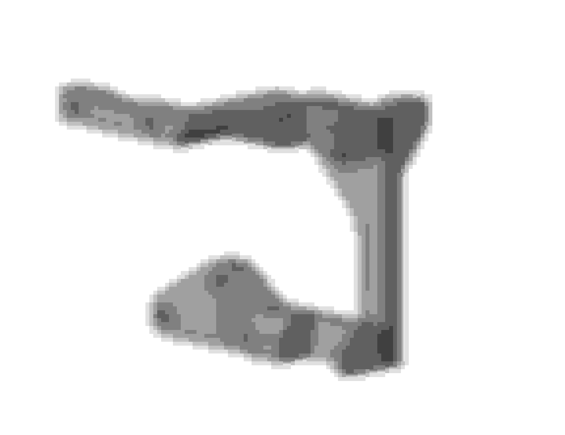
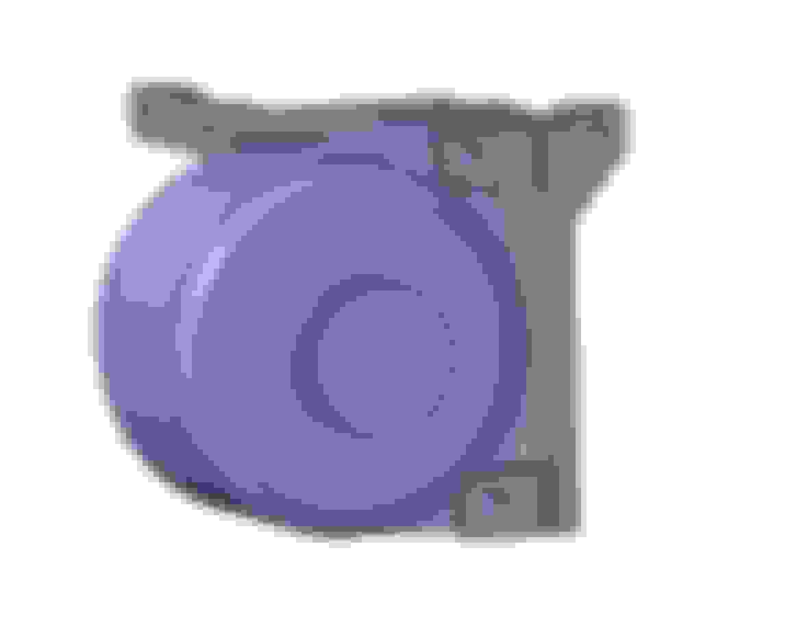
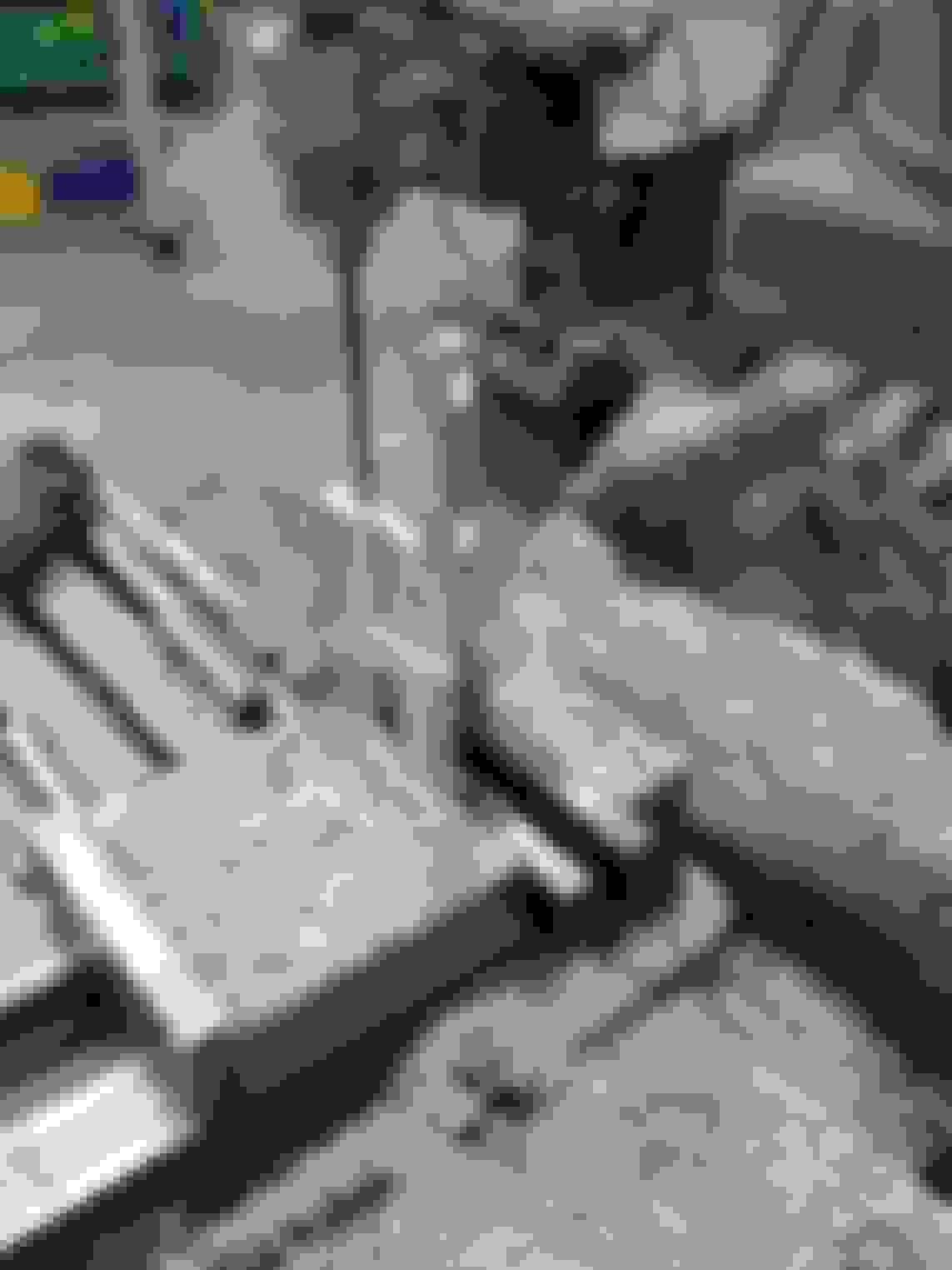
I've made it about as far as I can fabrication-wise without having the actual turbos here, which I'll be ordering probably next week. So I tackled the accessory drive setup. I went thru a couple iterations and am liking this setup.. sure is handy having a 3D model of an LS3 longblock. The alternator bracket is a 3 piece design which I think I'll CNC at work. Top and bottom alternator bolt pieces are pretty rigid and double shear on the alternator mounting, with a vertical 3rd piece to link the two together as well as locate/mount a redirect pulley.
I'll make a new power steering pump bracket to lower the pump 2" lower to get it further away form downpipe and wastegate pipe heat, and to eliminate the old alternator mounting stuff. The last design of two plates with simple turned spacers was easy to make and worked well and seemed very rigid once mounted.
The likely belt routing that I'll try out, for low everything...
You have a lot of extra time on your hands. That, or you never sleep. LOL
Haha! Actually I am usually so damn busy with other projects outside of work that I never have any downtime... can't remember the last weekend I had nothing lined up. But I've been itching to wrench on the Nova for the better part of 2+ years, so I've put everything else on hold to finally give her some much deserved love! Turbo updates to come verrrry soon...
An idea I'm playing with is sealing off the area behind the headlights and corner lights from the engine bay heat, and having ducts from under the bumper direct air up into the air filter area located behind the headlight.
Put the inlet above the air dam and suck up that sweet, dense air (although less benefit on a turbo car). You'd want to close off the area behind the filter. The inner fender has the flat for the battery tray, which you could cut and modify accordingly. Doable.
Put the inlet above the air dam and suck up that sweet, dense air (although less benefit on a turbo car). You'd want to close off the area behind the filter. The inner fender has the flat for the battery tray, which you could cut and modify accordingly. Doable.
Yep that's exactly the plan. In the future I'm going to make some variety of a splitter/airdam, so will have an inlet ctuout somewhere on it above the horizontal splitter piece and below the bumper closeout. But until that happens, I'll just close out the area from the engine bay (except for a 4" pass-thru tube to connect filter to turbo intake elbow), trim off the battery flat panel, extend the inner fender downwards closer to the bottom of the subframe rails, and pull air from that bottom open area.
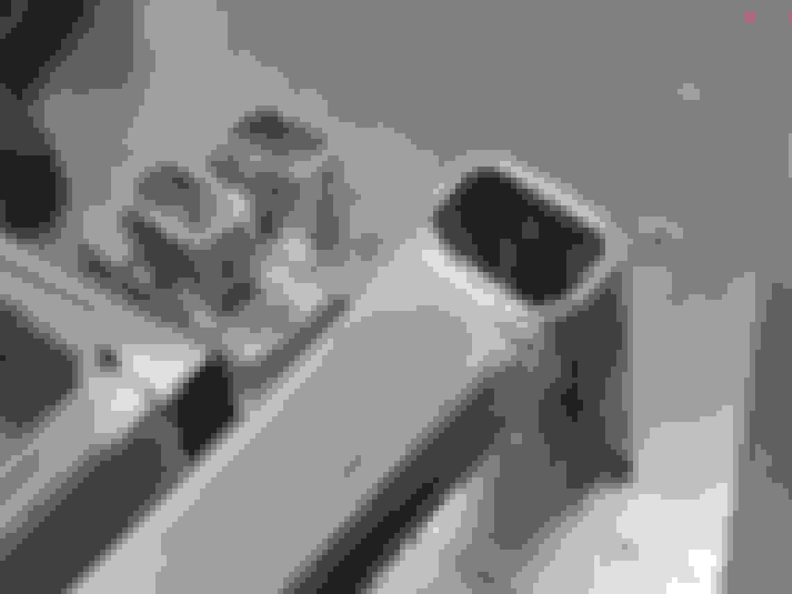
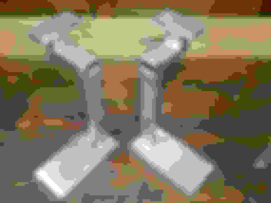
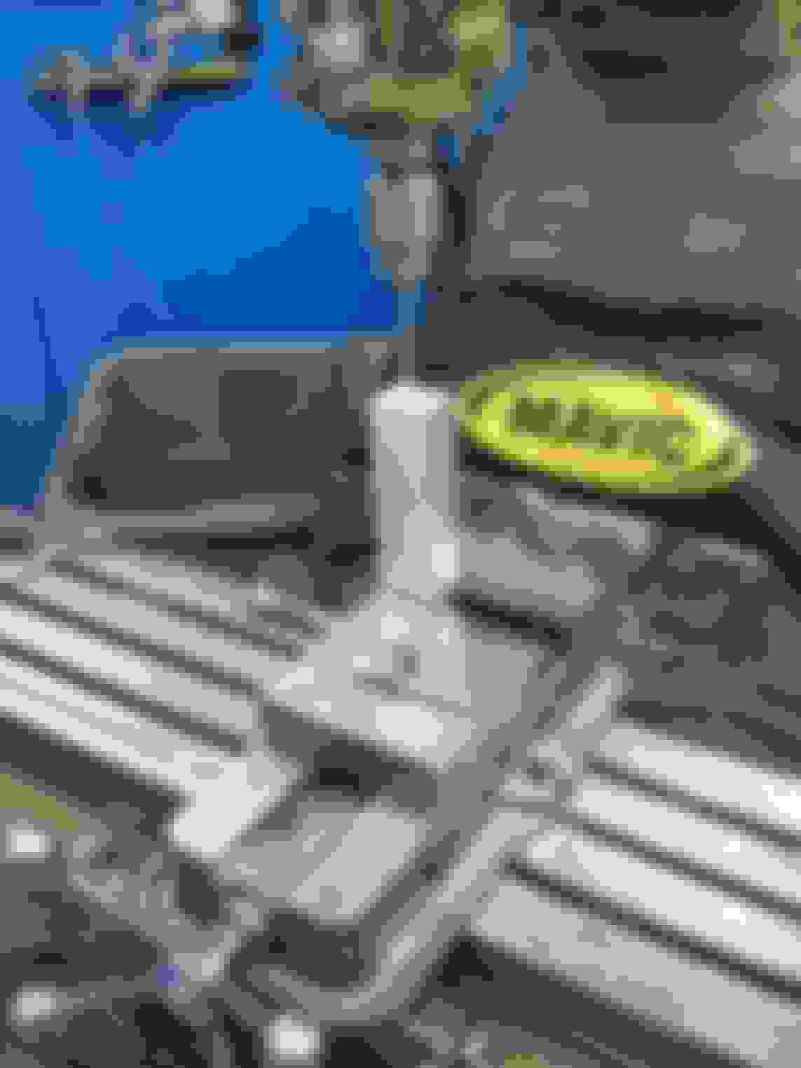
Because for absolutely no good reason, I made some mirrored aluminum turbo stands to hold the turbos in place while making the piping. The wood stand was wobbly and kinda of ghetto, and would get in the way of the tire at full lock, as well as likely being bulky and in the way for the wastegate routing back to the downpipe. Used bearings as height spacers so that I have the option to move the turbo down from its current height for mockup/fabrication if I need.
This stand is so lonely on the passenger side.. good thing I ordered turbos today!
While I wait for turbos.. I decided to get cracking on real-life alternator brackets to test fit this weekend. Took about 6 hours total, but should be worth it. Haven't yet made the 3rd piece which is the side plate that bridges the upper and lower brackets as well as provide a mounting point for a redirect pulley. I want to test fit these two brackets first to make sure their location and offsets are accurate to the LS3 3D model I have.


 11-12-2017 | 12:05 PM