When you click on links to various merchants on this site and make a purchase, this can result in this site earning a commission. Affiliate programs and affiliations include, but are not limited to, the eBay Partner Network.
Electrical Connector Information for LSx (Gen-III/ IV SBC) Transmission (4L60E/ 4L65E/ 4L70E) Swaps.
(4L80E/ 4L85E Transmission Electrical Connectors will not be discussed in this Thread).
The 4L60E/ 4L65E/ 4L70E Family of Transmissions uses 3 different types of external Electrical Connections.
All of which received revisions/ updates and changes over the 20-Years of Production, and nearly another 10-Years Post-Production.
The First type is the "Main Electrical Connector".
This Connection is located on the Passenger Side of the Transmission Case, passes through the Case, and is responsible for all Internal Electrical Connections.
The Male Connector and Female Connector, that make-up the "Main Electrical Connector" can be seen in the Image below:
More information regarding the "Main Electrical Connector" will follow later in this Thread.
The Second type of external Electrical Connection, is the Vehicle Speed Sensor/ Transmission Output-Shaft Speed Sensor Electrical Connector.
On 2-Wheel Drive Vehicles, this Electrical Connection and Sensor are found within the Transmission Tail-Housing.
On 4-Wheel Drive Vehicles, this Electrical Connection and Sensor are found within the Transfer-Case Assembly.
The 2 Images below show the 2-Wheel Drive VSS location, and the Electrical Connector for it:
More information regarding the Vehicle Speed Sensor/ Transmission Output-Shaft Speed Sensor Connector, will follow later in this Thread.
The Third and Last type of external Electrical Connection, is the Neutral-Safety/ Park Neutral Position (and Reverse-Range Illumination) Switch Assembly Connectors.
The Neutral-Safety/ Park Neutral Position (and Reverse-Range Illumination) Switch Assembly is located on the Driver Side of the Case at the Selector-Shaft/ Linkage Connection.
The 3 Images below, show the Neutral-Safety/ Park Neutral Position (and Reverse-Range Illumination) Switch Assembly... and corresponding Electrical Connectors:
More information regarding the Neutral-Safety/ Park Neutral Position (and Reverse-Range Illumination) Switch Assembly Connectors, will follow later in this Thread.
From the time of the Original 4L60E Product release (In 1992 for the 1993 Model-Year) to the Current Products available (2022)...
There were many revisions/ updates and changes that would affect the appearance, the Part-Numbers, and the function of all of these Electrical Connectors.
I will be going over the 3 different types of External Electrical Connection...
and all of the changes that have occurred over the last 30-Years.
This will cover Appearance, Function, and Terminal Pin-out changes.
Last edited by vorteciroc; Apr 12, 2022 at 06:18 PM.
Most people, as well as the Members here...
Are more likely to spend time working with the Female Connector (of the Main Electrical Connection) than the Male Connector.
Obviously this is due to the fact that the Female Connector is external to the Transmission...
and the Male Connector is internal/ inside the Transmission.
For this reason, I will be going over the Female Connector first...
Again, this is a Delphi Sealed Micro-Pack 100W 20-Way Female Connector.
As shown in the Image below:
The next Image below, is of the Female Connector, in the form of a replacement Pigtail Assembly.
This Image shows the Original appearance of the 12-Wire Female Connector at the time of Initial 4L60E Release (In 1992 for the 1993 Model-Year):
This Connector used a Dark-Grey Colored Body, with a Green Colored TPA:
The Multi-Cable Seals could be Brown, or Green, or White, or even a Translucent skin-tone Color that was referred to as "Natural":
The Connector would most of the time also use a Black Conduit-Clip, where the Convoluted Conduit meets the Connector Body:
When Multi-Cable Seals that were used, that had more Holes than needed...
Blue Colored Terminal Dummy-Plugs would be installed to seal the unused Holes om the Multi-Cable Seal:
The following Part-Numbers are for the FIRST version of the FEMALE Main Electrical Connector that uses 12-Terminals:
-Connector Body with 12-Way Multi-Cable Seal Delphi: #12160492 (Obsolete, Discontinued and Replaced by New Part).
-TPA Delphi: #12160494 (Active, Current, However Color has been Changed from Green to Light-Grey/ White).
-Terminals Delphi: #12084912 (Obsolete, Discontinued and Replaced by New Part).
-Terminal Dummy-Plugs Delphi: #12129557 (Active, Current).
-Conduit Clip Delphi: #12176394 (Active, Current).
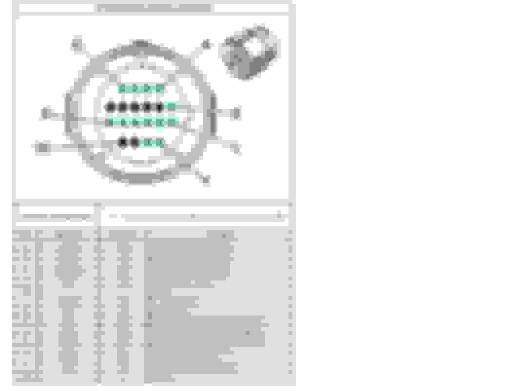
The FEMALE 12-Way Connector Pinout is shown below, as if looking at the FACE of the Connector...
NOT the back-side of the Connector, where the Multi-Cable Seal is located.
The GREEN Pin-Locations are where Terminals are installed... Black shows unused Pin-Locations:
The 12-Terminal Pin-Out was used for the 1993 and 1994 Model Years, with the appearance/ Colors shown for the Female Connector in this Post.
In 1995 a 13TH Terminal was added at the "U" Location (It was used for the addition of the PWM TCC Solenoid).
The 1995 through 2002 Model Years would use this 13-Terminal Pin-Out, with the appearance/ Colors shown for the Female Connector in this Post.
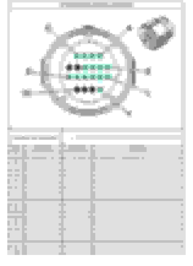
The following Part-Numbers are for the FEMALE Main Electrical Connector that uses 13-Terminals:
-Connector Body with 13-Way Multi-Cable Seal Delphi: #12160493 (Obsolete, Discontinued and Replaced by New Part).
-TPA Delphi: #12160494 (Active, Current, However Color has been Changed from Green to Light-Grey/ White).
-Terminals Delphi: #12084912 (Obsolete, Discontinued and Replaced by New Part).
-Terminal Dummy-Plugs Delphi: #12129557 (Active, Current).
-Conduit Clip Delphi: #12176394 (Active, Current).
From 2003 on, the Female Connector would change...
Last edited by vorteciroc; Apr 12, 2022 at 06:21 PM.
It is very common for GM, ACDelco, and Delphi Parts to have their corresponding Part-Numbers changed, merged, or discontinued after a long period of time.
As such, many of the Original Part-Numbers for the Parts discussed here... have either changed, merged, or been discontinued.
I will be using current Part-Numbers for current Parts, and some Part-Numbers for Research/ History purposes ONLY.
The appearance of the Female Connector remained the same until the Early-2000s.
Around the 2003 Model Year, the appearance of the Female Connector would change to look as the Current Version does Today.
Current Updated appearance (2022):
This Connector used a Light-Grey/ White Colored Body, with a Light-Grey/ White Colored TPA:
The Multi-Cable Seals are most often a Light-Grey/ White Color:
The Connector would use a Light-Grey/ White Color Conduit-Clip:
When Multi-Cable Seals that were used, that had more Holes than needed...
Blue Colored Terminal Dummy-Plugs would be still be used:
The following Part-Numbers would be used (TODAY) to create a CURRENT version of the FEMALE Main Electrical Connector that uses 12-Terminals.
(NOTE: The more modern versions of the 4L60E, do NOT use 12-Way Connectors anymore... They use either 13, 15, or 17-Way versions):
-Connector Body with 14-Way Multi-Cable Seal Delphi: #13603407 (2 Holes need to be Plugged, so that 12 Terminals can be used).
-TPA Delphi: #12160494 (Color has been Changed from Green to Light-Grey/ White).
-Terminals Delphi: #15359002.
-Terminal Dummy-Plugs Delphi: #12129557
-Conduit Clip Delphi: #12110725
For the 13-Terminal Version of this Connector, all the same Parts (that are shown above) are used as the 12-Terminal Version less one Plug.
For both the 15-Terminal and 17-Terminal Versions, the Multi-Cable Seal needs to be replaced.
Delphi: #12191762 is the Multi-Cable Seal that can be used for 15-Terminal and 17-Terminal Versions.
It is a Multi-Cable Seal with all 20 Terminal Locations OPEN... Just plug-off the unused holes.
Additional Terminal Dummy-Plugs (Delphi: #12129557) would also be used.
Also try Part-Number 12034413; it is a taller Plug that I like better than the other Plug Posted.
The Delphi Sealed 20-Way Micro-Pack 100W Series Connection-System is a much larger System (Many more Connector Versions and Parts) than what was just used for the 4L60E Transmission.
This Connector Series was used for many different GM Electronic Automatic Transmissions starting in the 1990s and through the 2010s.
This Connector Series was for GM Corporate Front-Wheel Drive Trans-Axles, Rear-Wheel Drive Transmissions, as well as some of the Allison Model Transmissions.
Some Transmission Model examples are GM: 4T40E, 4T45E, 4T60E, 4T65E, 4T80E, 4T85E, 4L60E, 4L65E, 4L70E, 4L80E, 4L85E...
Allison: 1000 and 2000...
As well as several more Models that I have not mentioned...
The C5 and C6 Corvette Torque-Tube System also had there own dedicated Versions of the Delphi Sealed 20-Way Micro-Pack 100W Series Connectors.
The Female (External) Connector Bodies were produced in several different Versions and in different Colors.
Examples:
The Multi-Cable Seal for the Female (External) Connector Bodies, were produced in almost 30 different Versions and Colors.
Examples:
The TPA for the Female (External) Connector Bodies were produced in several different Versions (some in different Key-Ways) and in different Colors.
Examples:
There were also many different Terminal Location Pin-out Designs...
Different amounts of Terminals used (from 11 Terminals used, up to 20 Terminals used) and with the Terminals arranged in different Designs.
Examples:
The Image above does not show much Detail (Sorry I am not permitted to show more)...
However there are over 30 Different Pin-out Arrangements (15 of them are in the Image above).
Lastly, there were different Accessories used; like Terminal Dummy-Plugs, and different Conduit-Clips used.
Examples:
Last edited by vorteciroc; Apr 12, 2022 at 06:24 PM.
As stated earlier, there are a few different Connector Pin-out arrangements for the different Model-Years of the 4L60E/ 4L65E/ 4L70E Transmission Family.
The GREEN Pin-Locations are where Terminals are installed... Black shows unused Pin-Locations.
The Pin-out arrangement for the 1993 and 1994 Model-Years is shown below (also shown in the Previous Post #2):
The Pin-out arrangement for 1995 through 2005 Model-Years, remains the same as the 1993 and 1994 Version...
But with the addition of 1 Terminal at Location: "U".
The use of Terminal Location "U" was for the addition of the PWM Control TCC Solenoid.
Pin-out arrangement for the 1995 through 2005 Model-Years is shown below:
The Pin-out arrangement for 2006 through 2008 Model-Years, remains the same as the 1995 through 2005 Version...
But with the addition of 2 Terminal Locations: "K" and "V".
The use of Terminal Locations "K" and "V" are for the addition of the Turbine Speed Sensor/ Input Speed Sensor (ISS).
Pin-out arrangement for the 2006 through 2008 Model-Years is shown below:
The Pin-out arrangement for 2009 and Newer Model-Years, is completely different from all previous Versions.
Pin-out arrangement for the 2009 and Newer Model-Years is shown below:
Regarding the 2009 and Newer Model-Year Transmissions (Shown ABOVE)...
The Significant changes to the Terminal-Locations/ Arrangement (Pin-Out) were do to the Following Internal Transmission CHANGES:
-The REMOVAL of the "Fluid Pressure Switch Manifold Assembly".
-The REMOVAL of the "3-2 Control Solenoid".
-The ADDITION of the "Internal Mode and Position Switch Assembly".
Also, EXTERNALLY the Park/ Neutral Position and Reverse-Lamp Switch Assembly was REMOVED.
Part of the reason that the Pin-out/ Terminal arrangements changed through the different Model-Years...
Is due to the Transmission Internal Wiring-Harnesses changing.
Parts and/ or Technology improvements also were reason for changes to have occurred.
Last edited by vorteciroc; Jan 19, 2024 at 12:23 AM.
The Male Connector is a Case Pass-Through Connector, and part of the Transmission Internal Wiring-Harness.
Again, this is a Delphi Sealed Micro-Pack 100W 20-Way Male Connector.
Just as the Female Connector was produced for many different Model Transmissions...
in many different Versions, and in many different Color Combinations...
So was the Male Connector.
The Image below shows 3 of the 4 different Male Connectors (Bodies and TPAs) that were produced in 4 different Colors:
The next Image shows some of the different Versions of the TPAs produced.
Below shows some of the TPA Colors that were produced, out of the more than 30 Versions made to date:
It is important to know that the Internal Wiring-Harnesses changed several times through the Model-Years.
The Different Versions are:
-1993.
-1994.
-1995.
-1996 through 2002.
-2003 through 2005.
-2006 through 2008.
-2009 and Up.
From the first Model-Year (1993) of the 4L60E/ 4l65E/ 4L70E, through 2002...
The Male Connector appeared as in the Image Below:
As in the Image above; the Male Connector used a Dark-Grey Colored Body, and a TPA that is Colored Dark-Green and White.
A Green Colored O-Ring Seal also goes around the outside of the Connector Body.
The Part Numbers for the Male Connector are as follows:
-Connector Body Delphi: #12160781 (Active, Current).
-TPA Delphi: #12146394 (Active, Current, However Color has been Changed from Dark-Green and White to Tan/ Brown and White).
-Terminals Delphi: #12160551 (Active, Current).
-Seal O-Ring (Connector to Transmission Case) Delphi: #12129390 (Active, Current).
The Internal Wiring-Harnesses that used the Version of Male Electrical Connector in the 2 Images above were:
-1993 (a 1-Year ONLY Version).
-1994 (a 1-Year ONLY Version).
-1995 (a 1-Year ONLY Version).
-1996 through 2002.
At this time I do not have Images of the different Internal Wiring-Harness that were used from the 1993 Model-Year, through the 2002 Model-Year...
Except for the Version of the 1996 through 2002 Internal Wiring-Harness.
The other Versions, that I do not have Images for, are discontinued...
and the Aftermarket Versions of those Internal Wiring-Harness do not appear like the Original Versions did from Delphi.
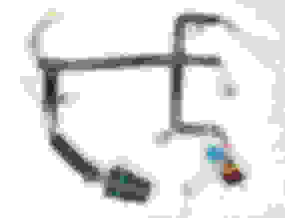
The 1996 through 2002 Version of the Internal Wiring-Harness, is GM/ ACDelco: #24298353.
It is shown in the Image below:
For the 2003 Model-Year; the appearance of the Female Electrical Connector would change in color (to Light-Grey/ White).
Shown in the Image below, the New color (Light-Grey/ White) on the Left, and the previous color (Dark-Grey) on the Right:
The Male Connector also made the same Color change as the Female Connector.
The Image below shows the Male Connector Body Color to be Light-Grey/ White, Delphi: #13510422 (and NO longer Dark-Grey):
The TPA for this Version of the Male Connector also changed.
The previous Version of the TPA (Delphi: #12146394, Dark-Green with White Colors) was not used for this Version of the Male Connector.
Instead a New TPA was used, Delphi: #12146748 ...and had Medium-Green with Light-Green Colors.
The Image below shows the TPA used for this Version of the Male Connector:
As in the 2 Images above, the 2003 through 2005 Version of the Male Connector uses the Part Numbers which follow:
-Connector Body Delphi: #13510422 (Discontinued, Light-Grey/ White Color).
-TPA Delphi: #12146748 (Discontinued, Medium-Green with Light-Green Colors).
-Terminals Delphi: #12160551 (Active, Current).
-Seal O-Ring (Connector to Transmission Case) Delphi: #12129390 (Active, Current).
The Internal Wiring-Harness that used this Version of Male Electrical Connector in the 2 Images above was:
-2003 through 2005.
The 2003 through 2005 Version of the Internal Wiring-Harness, is GM/ ACDelco: #24234280.
It is shown in the Image below:
Last edited by vorteciroc; Apr 12, 2022 at 06:28 PM.
For the 2006 Model-Year; the appearance of the Male Electrical Connector would change again.
This time, to the Color Black.
The Image below shows the Black Color Male Connector Body, Delphi: #13510422 (and NO longer Light-Grey/ White):
The TPA for this Version of the Male Connector actually changed back to the Original Part used...
However, the Color of this TPA was no longer produced in the Dark-Green and White Color.
The new Color for this TPA would be Tan/ Brown and White (but keep the same Part-Number as when it was Dark-Green and White).
The Image below shows this TPA (Delphi: #12146394) in the Early Color on the Left, and the Newer/ Late Color on the Right:
The Image below shows this TPA, as it is used for this Version of the Male Connector:
As in the 3 Images above, the 2006 through 2008 Version of the Male Connector uses the Part Numbers which follow:
-Connector Body Delphi: #15443076 (Discontinued, Black Color).
-TPA Delphi: #12146394 (Active, Current, However Color has been Changed from Dark-Green and White to Tan/ Brown and White).
-Terminals Delphi: #12160551 (Active, Current).
-Seal O-Ring (Connector to Transmission Case) Delphi: #12129390 (Active, Current).
The Internal Wiring-Harness that used this Version of Male Electrical Connector in the 3 Images above was:
-2006 through 2008.
The 2006 through 2008 Version of the Internal Wiring-Harness, is GM/ ACDelco: #24234121.
It is shown in the Image below:
For the 2009 Model-Year; the appearance of the Male Electrical Connector would change again.
This time, to the Color Blue.
The Image below shows the Blue Color Male Connector Body, Delphi: #13539169 (and NO longer Black):
The TPA for this Version of the Male Connector actually remained the same as the last Version of the Male Connector (Black, Delphi: #15443076).
The Tan/ Brown and White Color TPA is again Delphi: #12146394... and is shown again in the Image below:
As in the 2 Images above, the 2009 and Up Version of the Male Connector uses the Part Numbers which follow:
-Connector Body Delphi: #13539169 (Discontinued, Blue Color).
-TPA Delphi: #12146394 (Active, Current, However Color has been Changed from Dark-Green and White to Tan/ Brown and White).
-Terminals Delphi: #12160551 (Active, Current).
-Seal O-Ring (Connector to Transmission Case) Delphi: #12129390 (Active, Current).
The Internal Wiring-Harness that used this Version of Male Electrical Connector in the 3 Images above was:
-2009 and Up.
The 2009 and Up Version of the Internal Wiring-Harness, is GM/ ACDelco: #24237980.
It is shown in the Image below:
Last edited by vorteciroc; Apr 12, 2022 at 06:30 PM.
I was not going to bother to include this, but o...well.
There is also one other (Rare/ Odd-Ball) Version of the Main Connector to go over.
Most likely you will never ever see it...
It was a very short lived Version (that was used for 1 to 2 Years) in C/K Trucks that had a 4L60E with a Hybrid-Electric 5.3L Engine.
This Version of the 4L60E Family Transmission, required the addition of an Electric-Pump.
The Electric-Pump would be in the Sump, to Pump the ATF when the Engine was off (in Hybrid-Electric Mode).
This Power-Train option was quickly replaced with a purpose-built Auto-Transmission (2ML Series: 2ML70) for Hybrid-Electric use for the 2007 Model Year.
The 2ML70 Automatic Transmission was a Partnership-Collaboration between GM, BMW, Chrysler, and Mercedes/ Daimler.
GM's previous Venture/ Collaboration with ZF Transmission for the GM 6L Family was quite successful (GM, Ford, BMW, VW/ Audi, Etc)...
and decided to go the route of another Collaboration for the 2ML70 Transmission.
The Image below shows the Male Connector Body Color to be Light-Grey/ White (the same as I have Posted earlier).
However the TPA, and the Pin-Out are unique to this Version of this Connector.
The TPA is a Yellow with Orange Color... and this Version uses 15-Terminals (NOT the same as the previous 15-Terminal Pin-Out):
As in the Image above, this Version of the Male Connector uses the Part Numbers which follow:
-Connector Body Delphi: #13510422 (Discontinued, Light-Grey/ White Color).
-TPA Delphi: #------------- (Discontinued, Yellow with Orange Color).
-Terminals Delphi: #12160551 (Active, Current).
-Seal O-Ring (Connector to Transmission Case) Delphi: #12129390 (Active, Current).
This Version uses a different 15-Terminal Pin-Out than previously seen.
The Pin-out arrangement for this Version is shown below:
This Version of the Internal Wiring-Harness, is GM/ ACDelco: #24241821.
It is shown in the Image below:
TBC... I am still hunting down Part Numbers, and Service Information.
Last edited by vorteciroc; Apr 14, 2022 at 05:31 PM.
The 15 Terminal version of the Transmission has an Input Speed Sensor.
The 14th and 15th Terminals were added for the Two Wires of the ISS.
Installing one of these Transmissions into a Vehicle that originally had a 13 Terminal version Transmission, will work...
Just the ISS is disconnected/ ignored so to speak.
You should have the Shift Adapt process done after the Transmission swap.
I have researched for hours on this and it seems like if anyone would know how to do this it would be you. I have a 2009 4L60 (9SBD) that from what I can tell is for a Trailblazer 5.3. It has the blue connector. I have the Holley Terminator X Max and would like to be able to use this transmission since it is brand new and was free! I have seen a post from someone who said he just moved a few pins around at the connector but have also seen others say that I will have to swap to a pre-2009 valve body and internal wiring harness. Any advice would be amazing. Thanks
Correct 2009 and Newer Transmissions are not compatible with Holley EFI.
You would need to essentially convert the Transmission into a 2007-2008 Spec. Unit.
You would need to use the following new Parts:
-use a 2007-2008 Valve-Body and Manual-Valve.
-use a 2007-2008 External Transmission Wiring Harness.
-use a 2007-2008 Internal Transmission Wiring Harness.
-use a Fluid pressure manifold/ switch assembly.
-use a 3-2 Control Solenoid.
-use the 2007-2008 Manual Selector Shaft, Rooster-Comb, and Internal Parking Linkage.
-use an External Park/ Neutral and Reverse lights switch assembly.
-use External Wiring for the above Switch Assembly.
The 15 Terminal version of the Transmission has an Input Speed Sensor.
The 14th and 15th Terminals were added for the Two Wires of the ISS.
Installing one of these Transmissions into a Vehicle that originally had a 13 Terminal version Transmission, will work...
Just the ISS is disconnected/ ignored so to speak.
You should have the Shift Adapt process done after the Transmission swap.
IF I install a 13 Terminal version transmission into an ORIGINALY 15 Terminal version Transmission (2006 tahoe) will it still work properly?
NO
you can go the other way
15 into 13 is OK
13 into 15 is not OK
some will tell you that you can tune the 13 to work in place of the 15...in my experience that is not the case. There will still be intermittent issues and gremlins that plague the performance
FYI - as requested by the OP Vorteciroc, I deleted some posts to keep the thread on topic and the information accurate. There were a few "challenges" about unusual colors which could cause confusion and Vorteciroc suggested they be deleted. He plans to edit his previous posts to further reduce any confusion. Given how useful it is to have one of the original 4L60E engineers posting and educating us, I would like to keep his "master" threads as clean as possible.
Let me add to some of the questions here:
Post #14 (Boosted56): I have the similar Holley Dominator; I back-dated my 4L70e with a 2006 valve body and the other parts to make it electrically look like a 2006 trans.
Post #17 (GoldTeethActivities): The 15-Pin ISS versions of the 4L60E/4L70E are connected to a TCM (Transmission Control Module). Last I checked no one has figured out how to program or hack these GM TCMs to work properly with an Input Speed Sensor (ISS) signal. Just as MaroonMonsterLS1 says.
Last edited by mrvedit; Apr 13, 2022 at 05:46 PM.
Reason: Post numbers changed after another deletion
It is very common for GM, ACDelco, and Delphi Parts to have their corresponding Part-Numbers changed, merged, or discontinued after a long period of time.
As such, many of the Original Part-Numbers for the Parts discussed here... have either changed, merged, or been discontinued.
This further causes Fake/ Phony, Imitation Parts, that are Inferior (and at times even Un-Safe) to be produced.
Because some of the Electrical Connectors, that we have discussed...
are either discontinued/ unavailable or have had their appearance changed (does not look exactly like the Original Part)...
Plenty of "Knock-Off" or Cheap-Imitation Connector Parts exist.
The Image below shows a Terrible Chinese Phony Connector, that I have come across many times:
Often these Phony Parts will not fit-together properly, will leak ATF through the Connector, or may cause an Electrical-Short.
Just be careful of some of these Parts (many of which will claim to be "Original") when trying to save as much Money as possible.
7 Most Reliable High-Performance Engines GM Has Ever Built
Slideshow:These GM engines didn't just make huge power, they survived abuse, boost, track days, and six-digit mileage with a reputation for refusing to quit.
6 Common C5 Corvette Failures and What's Involved In Repairing Them
Slideshow: From wobbling harmonic balancers to failed EBCMs, these are the issues that define long-term C5 ownership and what repairs typically involve.
Retro Modern Bandit Pontiac Trans AM Comes With Burt Reynolds' Autograph
Slideshow: A modern Camaro transformed into a retro icon, this limited-run "Bandit" build blends nostalgia with brute force in a way few revivals manage.
Top 10 Greatest Cadillac V Series Performance Models Ever, Ranked
Slideshow: Cadillac didn't just crash the high-performance luxury vehicle party, it showed up loud, supercharged, and occasionally a little unhinged...
Coachbuilt N2A Anteros Is an LS2-Powered C6 Corvette In Italian Clothes
Slideshow: A one-off sports car that looks like a vintage Italian exotic-but hides a C6 Corvette underneath-just sold for the price of a new mid-engine Corvette.