When you click on links to various merchants on this site and make a purchase, this can result in this site earning a commission. Affiliate programs and affiliations include, but are not limited to, the eBay Partner Network.
Unless you are going to DIY a Sub-Harness/ Transfer-Case Electrical Harness Assembly...
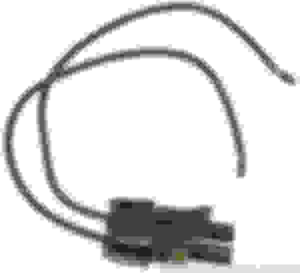
I am just going to Post the Electrical Connector Repair "PigTails" for you.
The Vehicle Speed Sensor Pigtail is: ACDelco #PT2298:
The Transfer-Case Low-Range Position Switch Pigtail is: ACDelco #PT2140:
I am sorry to say that, I should have already included/ Posted this Information (in this Thread)...
I never completed this Thread (which would have included this Information, if finished) due to:
-The time it takes to create.
-The low rate of Member activity.
-The overall lack of interest in this Subject/ Thread.
Anyway, should you have more Questions...
Post them here, as they pertain to the intended purpose of this Thread!
Good luck and have fun!
Thank you so much, that's exactly what i was looking for and i really do appreciate the indepth posts . Very informing man, excellent job!
@vorteciroc Firstly - thanks for the detailed and accurate information layed out above, however I have an issue related to the connectors that you may be able to help with.
I am from Australia and Holden Commodore VS model is the vehicle I have the 4L60E in.
I (without information) purchased a 2003 gearbox and quickly found out it was not an option.
Here is my issue - I then purchased a second 4L60E from the same model Holden Commodore - it appears to be incompatible with the electrical connector and also the fluid lines are larger (which indicated maybe a 7HDD transmission)
It is an AC DELCO rebuild and the connectors appear to be incompatible
Pictures attached - I would like to know what I actually have (I suspect a 7HDD with incorrect rebadge and Delco connector which is incompatible)
The green socket is the standard connector - 13 pin for the 6HDD
The Grey socket is the connector on the replacement transmission which seems incompatible it is a slightly larger diameter and the keyways are different, though the pins do appear to be in the same locations.
Do you recognise it and do you have any advice please. AC Delco badge 6HDD 8 13 pin from 6HDD Lable from 6HDD Connector from 6HDD 8
Thank you for your questions and interest in this topic. .
Some of the Information that you are looking for has already been provided in this Thread (multiple times).
I understand that this Thread can be painfully long to read in its entirety.
However the amount of information that requires explanation does not do well to be shortened...
It just results in more people asking unnecessary questions.
I an going to start with providing information to questions you posed that has nothing to do with this Topic.
The Transmission you have for your Vehicle is NOT one that would be Original to a Vehicle like yours.
6HHD is a 1996 Transmission that is normally installed in a GMC or Chevrolet G/H Van.
It is by no means a 2003 Core.
What it is...
Is a GM S.R.T.A Core (Service Replacement Transmission Assembly).
They can be installed into other Vehicles as part of a Warranty Repair, or Purchased over the Dealership Parts Counter.
Thank you so very much for your reply - My mention of the 2003 was an unintentional mis-direct - I purchased it before I realised just how much change was involved in the models.
The thank you is for the comment that the connector is missing the seal - hence the reason it looks different to the one with the green seal in place. Obviously my mechanic has also never seen one with the seal missing.
Is it likely in your opinion that the seal would have come out with the female loom plug when the wrecker removed it from the vehicle, and is it a simple matter to "just pop it back in", or even use the seal from the original 6HDD?
BTW - I did read the whole thread - the issue for me was in not recognising the incomplete connector on the "new to me" transmission.
Truth is, there is so much misinformation out there re these transmissions (at least on the Australian sites) that it was obvious from your content that you know these intimately.
Thanks again - I will be back to the mechanic tomorrow with the news.
EDIT @vorteciroc I removed the centre seal (green) from a 2001 box previously replaced in my sons car - all is good - I would never have recognised it for what it was without your comments and thread - Thanks again
Last edited by Peter Dohnt; Jan 26, 2023 at 09:25 PM.
I am working on finishing up my swap into a '61 Biscayne. I have a Lokar shifter which has no Neutral Safety or Reverse Light Output. I have purchased the connectors and module for my 4L60E. In order to get the Neutral Safety and Reverse Light Output, do I only need to worry about wiring the C2 connector? If I need to include the C1 connector, how do I include that into the wiring? If you have a diagram or schematic, that would be so helpful.
Correct 2009 and Newer Transmissions are not compatible with Holley EFI.
You would need to essentially convert the Transmission into a 2007-2008 Spec. Unit.
You would need to use the following new Parts:
-use a 2007-2008 Valve-Body and Manual-Valve.
-use a 2007-2008 External Transmission Wiring Harness.
-use a 2007-2008 Internal Transmission Wiring Harness.
-use a Fluid pressure manifold/ switch assembly.
-use a 3-2 Control Solenoid.
-use the 2007-2008 Manual Selector Shaft, Rooster-Comb, and Internal Parking Linkage.
-use an External Park/ Neutral and Reverse lights switch assembly.
-use External Wiring for the above Switch Assembly.
Is this still true? Holley has released a transmission harness, PN 558-455 for post 2009 transmissions.
Im assuming a software update is all I'll need for my terminator and this new harness and I should be in business.
You really should confirm this on a Holley forum. That harness is listed as working with a Holley Dominator, no mention of the "Terminator".
Give us an update if your confirm anything.
You really should confirm this on a Holley forum. That harness is listed as working with a Holley Dominator, no mention of the "Terminator".
Give us an update if your confirm anything.
Fair, I'll post it up there and see what I find. I have the harness in hand, and I have what I think is the correct software for the holley. Guess Ill try it and see if I brick something.
Reporting back as promised, the Holley system I have is labeled Holley terminator LS, but uses a dominator ECU. I updated for firmware version 6, from version 4, got the new harness and plugged it in, it actually has a positive click on the connector, and boom! All 4 speeds work as they should now. 2017 transmission working with the Holley.
how are you . I'm new to this group so from what I see I'm in the right place. My question is: I have a 4L65e 15-pin transmission (damaged). and got a 4l65e 17 pin transmission. is it possible for this transmission to work with my 2008 15 pin harness? either
I must change the valve body and internal harness of the 4l65 17pins...
Thank you very much for your support.
Last edited by galindo motors; Aug 18, 2023 at 03:31 AM.
how are you . I'm new to this group so from what I see I'm in the right place. My question is: I have a 4L65e 15-pin transmission (damaged). and got a 4l65e 17 pin transmission. is it possible for this transmission to work with my 2008 15 pin harness? either
I must change the valve body and internal harness of the 4l65 17pins...
But First I have to add to it/ Finish it with:
-ISS information
-More (Pressure Switch Manifold with external Neutral Safety Switch) vs (Internal Mode Switch without external Neutral Safety Switch) discussion.
-Holley NOW DOES have Harnesses and Controller Hardware/ Software for 2009+ 4L60E/ 65E/ 70E/ 75E Units.
-Additional Electrical Connector Break down, to build your own Internal Harness, when Early Models get Phased out in the Future.
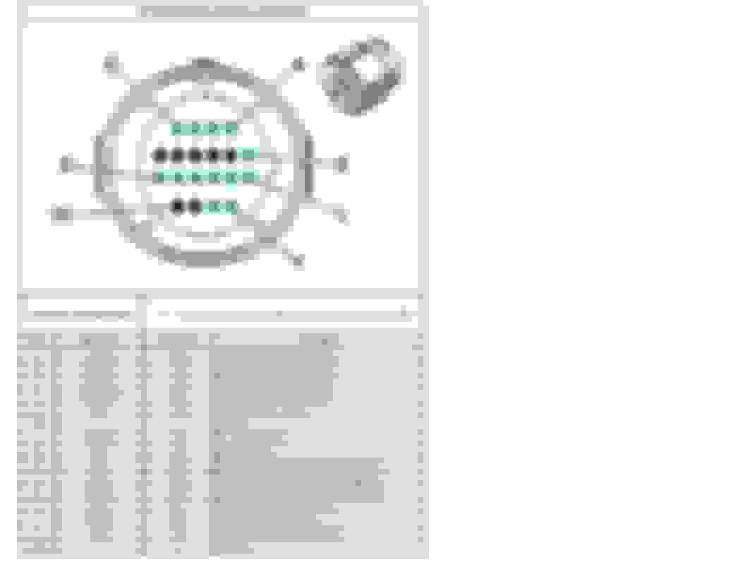
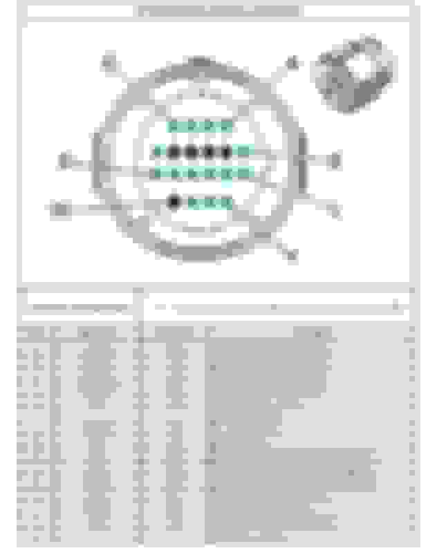
As stated earlier, there are a few different Connector Pin-out arrangements for the different Model-Years of the 4L60E/ 4L65E/ 4L70E Transmission Family.
The GREEN Pin-Locations are where Terminals are installed... Black shows unused Pin-Locations.
The Pin-out arrangement for the 1993 and 1994 Model-Years is shown below (also shown in the Previous Post #2):
The Pin-out arrangement for 1995 through 2005 Model-Years, remains the same as the 1993 and 1994 Version...
But with the addition of 1 Terminal at Location: "U".
The use of Terminal Location "U" was for the addition of the PWM Control TCC Solenoid.
Pin-out arrangement for the 1995 through 2005 Model-Years is shown below:
The Pin-out arrangement for 2006 through 2008 Model-Years, remains the same as the 1995 through 2005 Version...
But with the addition of 2 Terminal Locations: "K" and "V".
The use of Terminal Locations "K" and "V" are for the addition of the Turbine Speed Sensor/ Input Speed Sensor (ISS).
Pin-out arrangement for the 2006 through 2008 Model-Years is shown below:
The Pin-out arrangement for 2009 and Newer Model-Years, is completely different from all previous Versions.
Pin-out arrangement for the 2009 and Newer Model-Years is shown below:
Sorry for the blank Chart/ Diagram... I am still working on it.
A completed Chart/ Diagram will be available soon.
Part of the reason that the Pin-out/ Terminal arrangements changed through the different Model-Years...
Is due to the Transmission Internal Wiring-Harnesses changing.
Parts and/ or Technology improvements also were reason for changes to have occurred.
Do you have the completed 2009+ diagram yet? That's what I'm looking for and it is nowhere online it seams. Thanks!
Thank you for the update!
Its great and very useful to have all the different pinout variations in one place.
Sorry if this was answered above, but can a e.g. 2001 wiring harness be plugged into a 2009 transmission or are they keyed differently? Your images show the same key for all variations.
IIRC the pre-ISS and ISS are keyed the same, but the 2009 is keyed differently and an old harness will not plug in. (Lets hope that is true.)
UPDATE: Yikes - see vorteciroc's reply below - they are all keyed the same.
Thank you for the update!
Its great and very useful to have all the different pinout variations in one place.
Sorry if this was answered above, but can a e.g. 2001 wiring harness be plugged into a 2009 transmission or are they keyed differently? Your images show the same key for all variations.
IIRC the pre-ISS and ISS are keyed the same, but the 2009 is keyed differently and an old harness will not plug in. (Lets hope that is true.)
Yes an older (2001 wiring harness) can be plugged into a 2009 transmission...
The Connectors did not change in terms of "Keying".
So be very careful of accidentally Connecting anything 2009+ with anything Older... as the Circuits are located on different Terminals.
The 15 Terminal version of the Transmission has an Input Speed Sensor.
The 14th and 15th Terminals were added for the Two Wires of the ISS.
Installing one of these Transmissions into a Vehicle that originally had a 13 Terminal version Transmission, will work...
Just the ISS is disconnected/ ignored so to speak.
You should have the Shift Adapt process done after the Transmission swap.
Excuse my ignorance but, what is the shift adapt process? I�m in this situation right now, going to use a 4l60e trans from 2007 15 pin on a 2002 5.3 vortex setup 13 pin. What I�ve read, once installed I can take to tuner and he should be able to make it ignore the ISS from 2 extra pins correct?