Wheel alignment for 4th gen IRS swap
 06-03-2012, 12:57 PM
#21

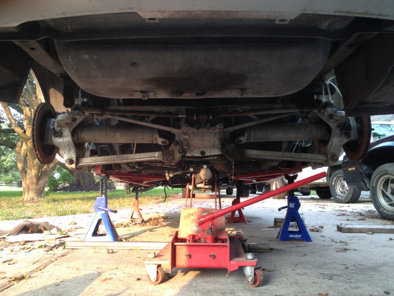
The bat-wing is DEFINITELY sitting to high. The toe bars need an additional 3-inches so I will have to "tweak" the bat-wing brakets, its seems.
However, the alignment is nearly dead on. I measures from the center of the axle to the outer fender. I also measured from the axle center to the front fender of the of the car and got the safe difference. With 1/32 of an inch.
Alignment is good, just needs a height adjustment.
However, the alignment is nearly dead on. I measures from the center of the axle to the outer fender. I also measured from the axle center to the front fender of the of the car and got the safe difference. With 1/32 of an inch.
Alignment is good, just needs a height adjustment.
 06-03-2012, 01:24 PM
#22
One more thing... Since Im going to be fabricating my own control arms, Im considering extending the length of the arms to combat toe travel at full compression. I figure that the increased radius will make the yolks travel with up and down with less curvature in their travel path.
Any input?
Any input?
06-03-2012, 05:11 PM
#23

If you lengthen the trailing arms, without changing the convergence point of the virtual swing arm, that will reduce the knuckle rotation. If you change the mounting locations at the body to move the arms farther apart (as Doug Rippie's brackets do for the C4) then you'll reduce wheel base length change, and change your anti-squat values.
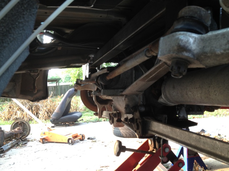
As for the differential, the toe rods need to be level at ride height for the rear to work at it's best. If you look at the rear, you'll notice the toe rods don't operate completely with in the same plane as the half shafts. As they move out of parallel they start to toe the wheels out. If you mount the diff too high, you'll have either wheels too high into the fender (to keep the toe rods level), or poor toe control.
As for the differential, the toe rods need to be level at ride height for the rear to work at it's best. If you look at the rear, you'll notice the toe rods don't operate completely with in the same plane as the half shafts. As they move out of parallel they start to toe the wheels out. If you mount the diff too high, you'll have either wheels too high into the fender (to keep the toe rods level), or poor toe control.
 06-03-2012, 09:39 PM
#24
If you lengthen the trailing arms, without changing the convergence point of the virtual swing arm, that will reduce the knuckle rotation. If you change the mounting locations at the body to move the arms farther apart (as Doug Rippie's brackets do for the C4) then you'll reduce wheel base length change, and change your anti-squat values.
As for the differential, the toe rods need to be level at ride height for the rear to work at it's best. If you look at the rear, you'll notice the toe rods don't operate completely with in the same plane as the half shafts. As they move out of parallel they start to toe the wheels out. If you mount the diff too high, you'll have either wheels too high into the fender (to keep the toe rods level), or poor toe control.
06-04-2012, 05:51 AM
#25
On The Tree
iTrader: (20)
Join Date: Mar 2007
Location: TX
Posts: 126
Likes: 0
Received 0 Likes
on
0 Posts

Thanks for directing me over Lee.
Ya tucking in the differential will be optimum for where you want the weight placed on the body; has to be placed within reason of 1 inch of stock C4 ride height for reasons stated by Lee above. As Lee has informed though toe rod clearance is an important issue that has to be addressed before permanent batwing mounts are placed. During compression of the knuckle/wheel, the knuckle rotates in the direction of wheel travel; which in turn rotates the outer toe rod and its mount into the batwing mount. The lack of clearance designed on the C4 makes the knuckle mount crucial so that it is set without the toe mount being too close at baseline ride height; the rotational mounting position is important along with the placement directly related to the forward placement of the differential. The best thing I found was:
1. Center knuckles
2. Properly hold knuckles in place rotationally
3. Mount entire rear setup and hold in place with jacks to adjust (includes camber rod, toe rod)
4. Tack weld the rear w/ mounts into the car
5. Artificially compress knuckle to your choice of max suspension travel
6. Estimate rotation of knuckle and make sure the toe mount clears the batwing bracket/bolt
7. At this point you can hold up the shock for where it should be at that point in time during travel and make sure all is clear as well
8. If all is correct get the pinion/yoke angle with the driveshaft properly set
9. Permanently weld in batwing brackets and front differential mount.
I hope this is clear, and if it isn't please let me know where I have failed to communicate and we can get you squared away (pun intended). All the work for this conversion is in the initial alignment before everything is set. Once you accomplish the differential alignment, everything else is easy from there; the differential is the most crucial piece. It looks like you are doing everything correctly so far. Just keep double and triple checking all these aspects as I'm sure you already are. Lee, you've done a great job guiding him!
Enjoy the project though, it is alot of fun, rewarding in the end, and definitely worth the effort and money! Keep the questions coming!
Last edited by 99_orange_SS; 06-04-2012 at 05:59 AM.
06-04-2012, 07:43 PM
#26
Speaking of mounting, what is the best angle for the lower trailing arm with the suspension sitting parallel? If I can find that, then the I can figure out the rest of the geometry.
Last edited by Driver_10; 06-04-2012 at 07:58 PM.
 06-05-2012, 07:36 AM
#28
I have my bracket diagram. You're going to be racing this thing so you may want to invest in a suspension analyzer, there are a bunch around. Find your CG height, rather than guess. When you build your brackets maybe go with a bracket like this, a suggestion 99_orange_ss made to me, since it will allow you to relocate your IC as needed:

That will allow you to experiment and find the best setting. My diagram has the center of the lower bolt hole at 5 1/4" (stock C4 arrangement) from the bottom of stock f-body LCA mount, angled back at 64.5�. That will angle the lower arm up slightly toward the body.
That will allow you to experiment and find the best setting. My diagram has the center of the lower bolt hole at 5 1/4" (stock C4 arrangement) from the bottom of stock f-body LCA mount, angled back at 64.5�. That will angle the lower arm up slightly toward the body.
06-05-2012, 05:30 PM
#29
I have my bracket diagram. You're going to be racing this thing so you may want to invest in a suspension analyzer, there are a bunch around. Find your CG height, rather than guess. When you build your brackets maybe go with a bracket like this, a suggestion 99_orange_ss made to me, since it will allow you to relocate your IC as needed:
That will allow you to experiment and find the best setting. My diagram has the center of the lower bolt hole at 5 1/4" (stock C4 arrangement) from the bottom of stock f-body LCA mount, angled back at 64.5�. That will angle the lower arm up slightly toward the body.
That will allow you to experiment and find the best setting. My diagram has the center of the lower bolt hole at 5 1/4" (stock C4 arrangement) from the bottom of stock f-body LCA mount, angled back at 64.5�. That will angle the lower arm up slightly toward the body.
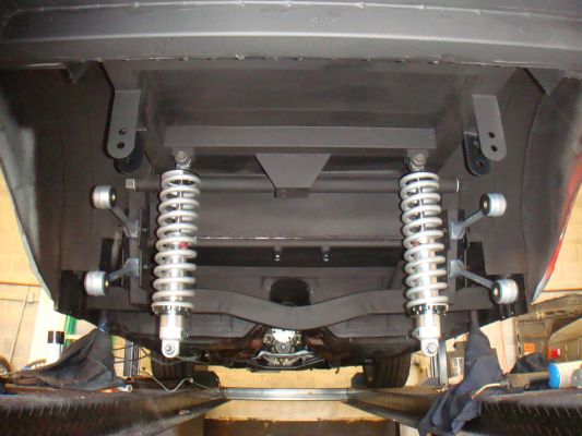
BTW... could you show me a few more picks of that shock mounting? Im definitely converting to a coil-over set-up.
06-05-2012, 09:00 PM
#30
I reused the leaf spring, that's the e30 local to me in philly, don't do it as he did.
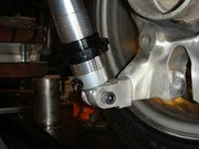
He effectively has a single sheer mount on the knuckle's shock bolt. There a number of C4 kits that do mount it just as he did. It works for him I guess, but I'd rather have more support.
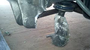
If it were to break as this one did, it'll ruin you're day.
It's putting the corner weight on a location that is not design for it. Use a bracket like this, which distributes the load.
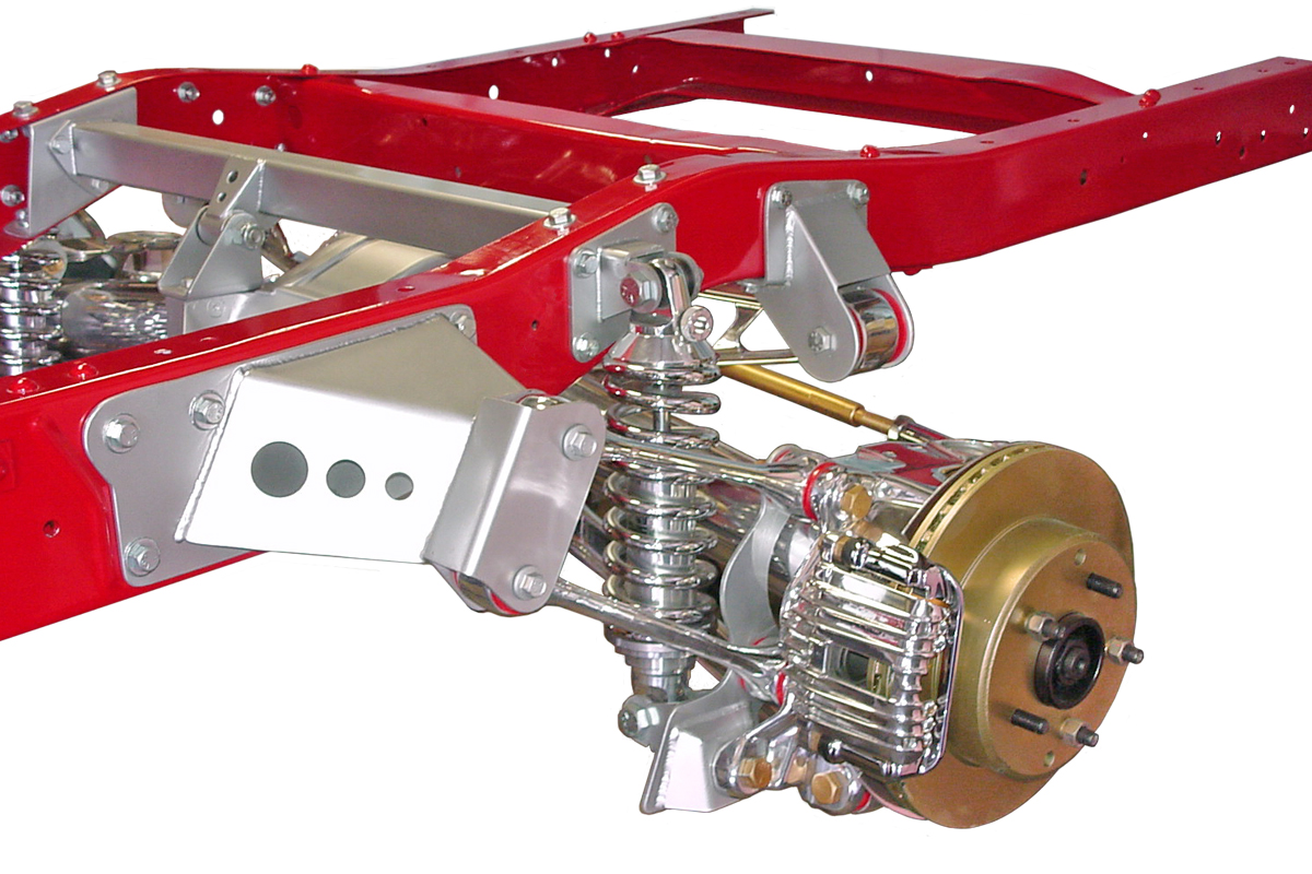
It's very similar to the Flat Out Engineering kit that is unfortunately no longer available.

The coilover bracket is available from Street Rod Garage, as for the trailing arm bracket 99_orange_ss will have to fill you in. I know Moly, and Moser sell 4 link kits with brackets almost exactly like that.
Last edited by lees02WS6; 01-04-2021 at 03:21 PM. Reason: grammar

 06-07-2012, 07:20 AM
#36
On The Tree
iTrader: (20)
Join Date: Mar 2007
Location: TX
Posts: 126
Likes: 0
Received 0 Likes
on
0 Posts
As Lee suggest I would highly recommend the S&W brackets. If you'd like to fab your own I can give you the distance necessary between the bolt holes along with the arc angle necessary for the top and bottom rod alignment. If you have a welder it is extremely simple. Even if you don't you could fab the 3 pieces of steel and go up to a local welder and have them assembled for a few bucks most likely. That coilover bracket from Street Rod is a necessity as well. Both of these brackets will allow for the absolute most adaptability and track tuning options.
Looking forward to watching your progress! Your doing your research before and it will definitely pay off big time. One other suggestion I would have is contacting Banski Motorsports for their trailing arms with omega clamps. The omega clams reduce the torquing on the rod end threads and will not ruin them. This will allow for more adjustment overtime without having to replace the swedge tubes or rods.
Looking forward to watching your progress! Your doing your research before and it will definitely pay off big time. One other suggestion I would have is contacting Banski Motorsports for their trailing arms with omega clamps. The omega clams reduce the torquing on the rod end threads and will not ruin them. This will allow for more adjustment overtime without having to replace the swedge tubes or rods.
06-08-2012, 12:41 AM
#37
I've got both a welder and a plasma cutter.
I think that ive got good idea how to calculate the radius of the control arm ark.
I'll take whatever specs that you have to give me.
I think that ive got good idea how to calculate the radius of the control arm ark.
I'll take whatever specs that you have to give me.
06-10-2012, 07:17 PM
#38
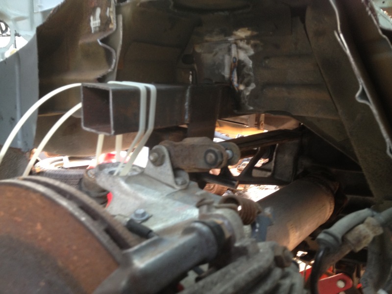
After my first attempted installation of the bat-wing, I found the the mounts that I made to be to flimsy feeling. After a good deal of frustration, using some of the good suggestions, I dove back into it.
Instead of trying to just weld some reinforcement to the extisting surface I opted to redo the mounts and start with a piece of 2X2 16 gauge tubing and weld the bat-wing mounts to it. (pretty much copied 99_orange_ss)
Then I installed the entire assembly on the alignment marks left by my first attempt. It looks and feel a LOT sturdier now and the install height needs a bit of tweaking but its TONS better then where I had it before.
06-10-2012, 08:53 PM
#40

At over $700 big ones, its a bit pricey, but Id rather reduce the chances of being covered in burning gas in case I end up in a ditch while "trying" to race.
I am a green horn after all.
