Wheel alignment for 4th gen IRS swap
 06-14-2012, 05:54 PM
#41

Well... It would seem that Ive injured my back, so it will be a while before I can do any more fab work. I spent the better part of the day getting some stuff ordered to finish the suspension swap.
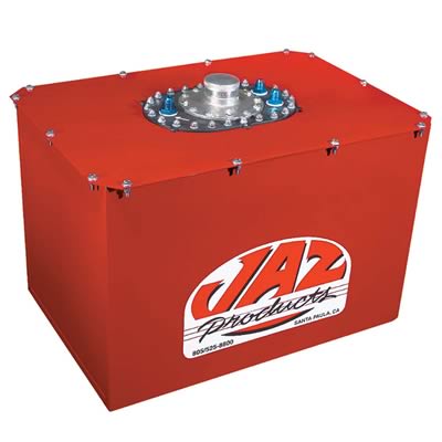
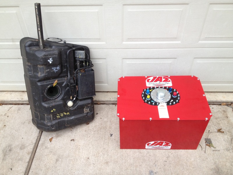
Ive ordered a new 26 gallon, bladdered, 25 x 17 x 18, "Jaz" fuel cell, and Ive ordered some 18 gauge mild steel sheeting to finish out the work in the rear.
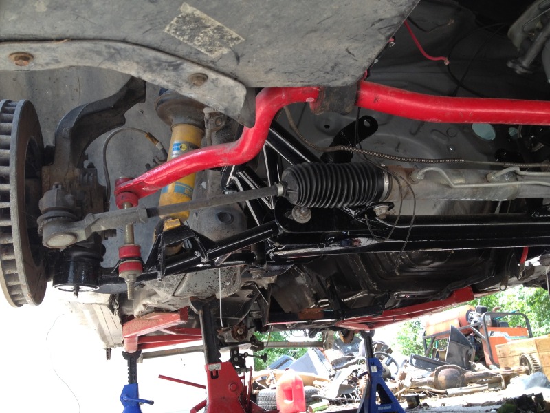
Ive got a new set "road-race" K-members installed in the car. They are tons beefier than the older K-members I hod on before.
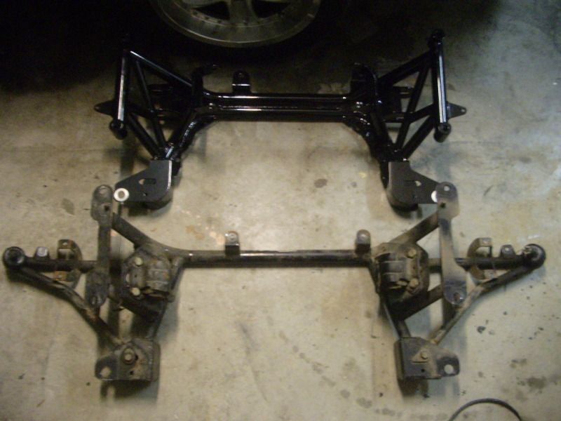
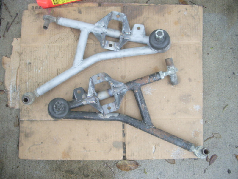
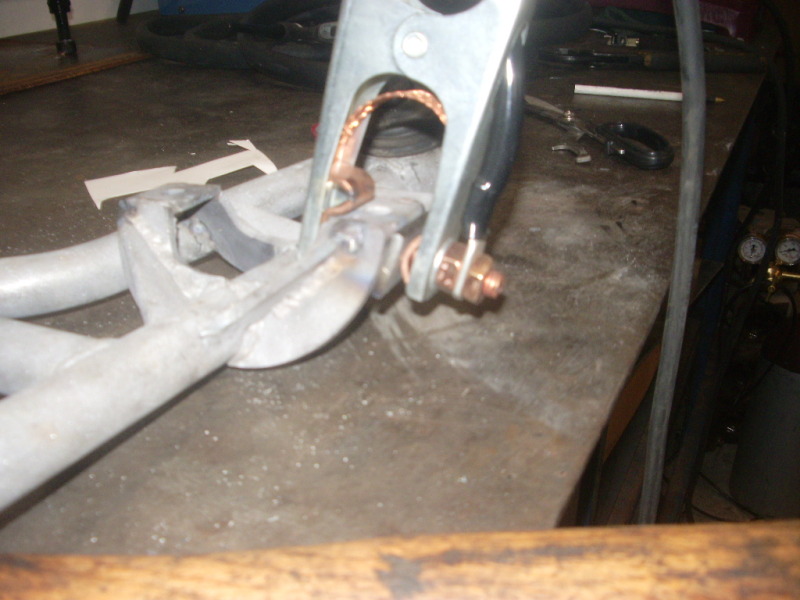
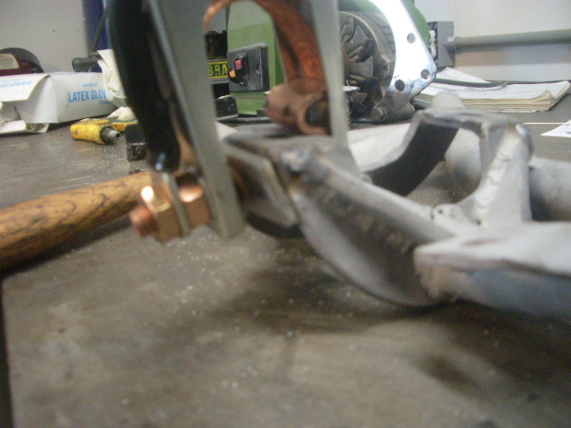
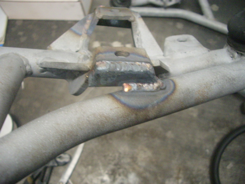
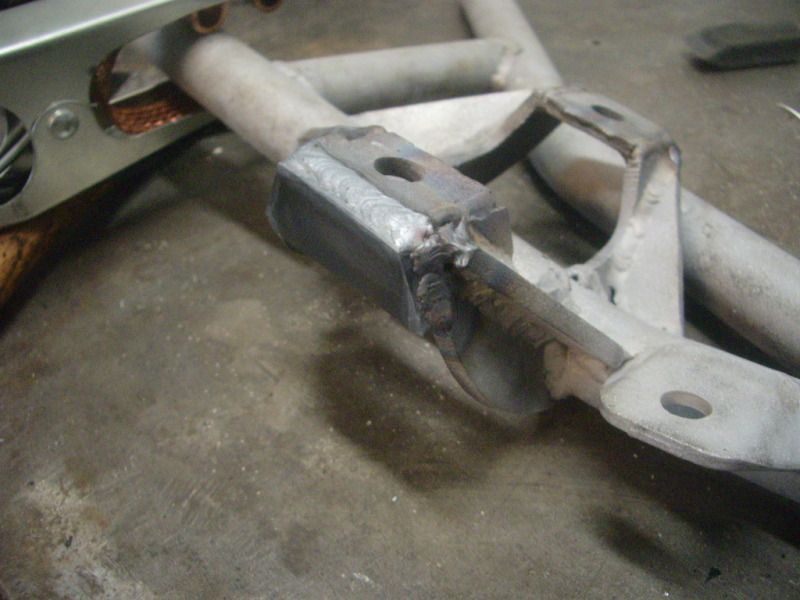
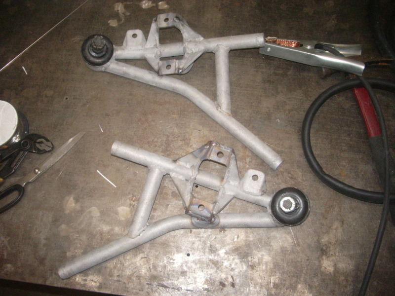
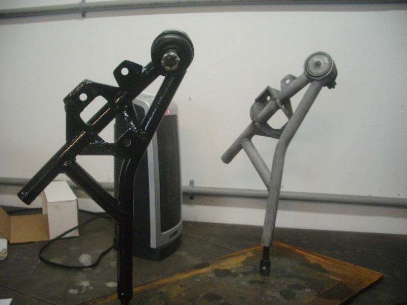
While I was at it. I figured that I would attend to some of the structural deficiencies of the aftermarket control arms. It would seem that they like to mend at the control arm perches. I sand blasted them, welded some re-enforcing gussets and coated them with them with POR-15.
Now they are better then new!
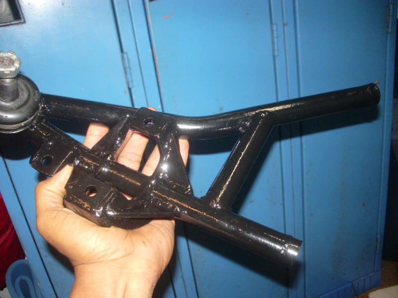
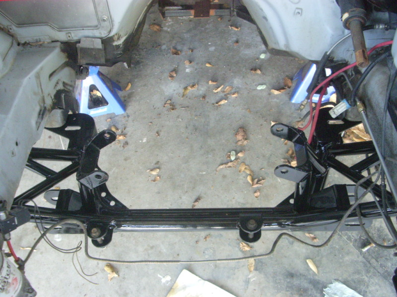
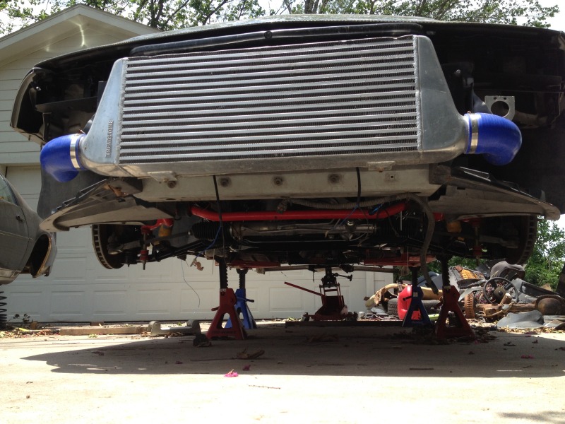
The front end is buttoning up pretty good.
Ive ordered a new 26 gallon, bladdered, 25 x 17 x 18, "Jaz" fuel cell, and Ive ordered some 18 gauge mild steel sheeting to finish out the work in the rear.
Ive got a new set "road-race" K-members installed in the car. They are tons beefier than the older K-members I hod on before.
While I was at it. I figured that I would attend to some of the structural deficiencies of the aftermarket control arms. It would seem that they like to mend at the control arm perches. I sand blasted them, welded some re-enforcing gussets and coated them with them with POR-15.
Now they are better then new!
The front end is buttoning up pretty good.
 06-21-2012, 06:13 PM
#42
On The Tree
iTrader: (20)
Join Date: Mar 2007
Location: TX
Posts: 126
Likes: 0
Received 0 Likes
on
0 Posts

Modifications to the front control arms are well done; they will no longer have issues at all! I personally have the rectangular tube ones that UMI just came out with, I was the lucky first customer and I have loved them!
Back to task. I figured I'd reply to your PM's on here to share the knowledge with the board.
Q1.) What is the optimal ride height geometry? A): The measurements you provided (center diff about 12 inches down from the top of the outer lip of the wheel wells with the hubs sitting parallel at ride height; 275 40 r18 will have about an inch and a half of space above them from the lip.) sound right on. I would now make sure your pinion angle is correct at this height which leads to your second question.
Q2.) Is there a proper pinion angle and what is it? A): Pinion angle is very important; Lee and I have talked about it extensively along with the functionality/limitations of U-joints. On the specific application of the drive shafts in our cars, the pinion angles must cancel each other out at zero but cannot each be zero on their own. The reason for this is that for a U-joint to properly function and last it has to be at flexion. Flexion allows for the caps to rotate, causing the needle bearings to move so they properly re-grease themselves. If the angle of each U-joint is zero then the trunnions and needle bearings wear prematurely/quickly causing said U-joint to fail. I would at a minimum try to get 1/2 degree of operating angle at each end of the drive shaft with 1 degree being optimal in our circumstance; both ends adding to zero of course. The position you described you have the differential at sounds like it is right where it needs to be; I cannot tell you this for sure though as you will have to mock it up and measure.
Let me/us know what that ends up measuring at as that will be great info for this posting.
The square tubing option is great, I proceed with that route of mounting as it increases the spread of the translation force across the car as well as inadvertently beefing up the rear frame since there were never any real crossbeams to begin with. For those wondering the batwing doesn't provide much help in this case and you do not want to rely on it as a crossbeam anyways, it needs to simply act as a mount for the differential and that is all. The crossbeam will have to be sitting pretty high in the car for the position of the differential that you have but this is not a factor for you since you are going with a new fuel cell anyways.
Just a heads up as well since you are getting into course racing. You will want to consider placement of the tank so you can have optimal center of gravity and weight distribution when sitting still and when entering/exiting turns.
Looking forward to more questions and the progress updates!
06-21-2012, 10:53 PM
#43
You will want to consider placement of the tank so you can have optimal center of gravity and weight distribution when sitting still and when entering/exiting turns.
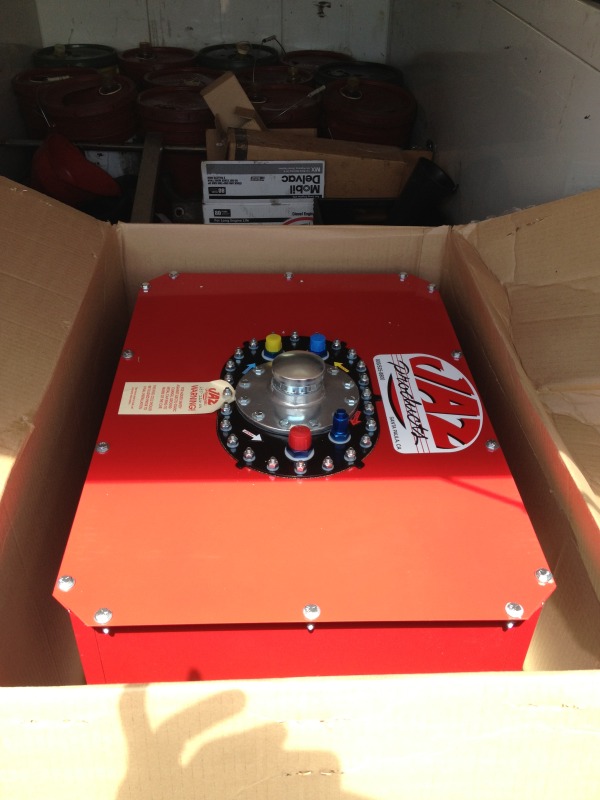
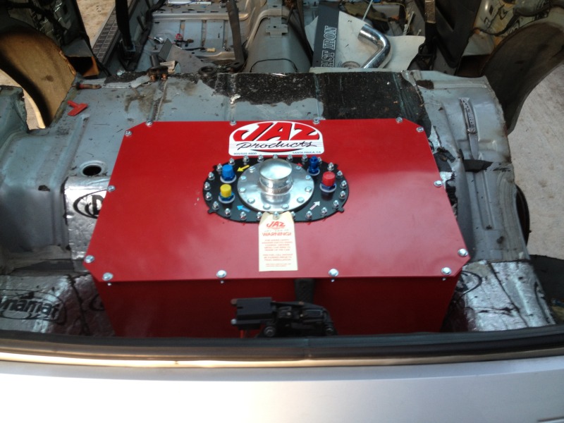
The fuel cell came with "anti-slosh" foam, "roll over" check valve, 8an return/ vent and 10an supply fittings. Its cost me $530 delivered
I got started on fabricating this "surge-tank" a little while back. Fuel will be fed into the surge-tank with a low pressure, high volume "puller" pump. The sumps at the bottom feed fuel to the two "pusher" high pressure pumps. Excess fuel drains back into the fuel cell. This ensures that the sump of the fuel pick-up will never go dry at hard corners or stops.

It will be next week before I can attempt to complete the swap (out of cash for metal right now x_x)
My cell install will be similar to this set-up.
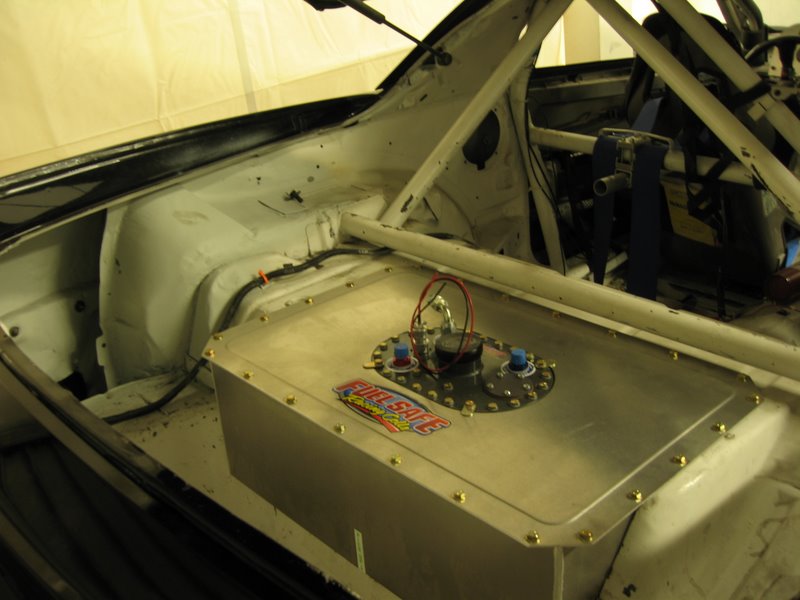
I will mount the cell as close to the diff, and as low in the frame as I can reasonably get it. The cell will have a 1.50 square tubing, mount box to give it a bit of "scrape" protection for unforgiving driveways. It will sit parallel with axle assembly. The gravity center for the fuel tank should remain near oem.
06-22-2012, 06:30 PM
#45
On The Tree
iTrader: (20)
Join Date: Mar 2007
Location: TX
Posts: 126
Likes: 0
Received 0 Likes
on
0 Posts
Sounds like you have the fuel cell under control. I like how that tank is mounted in the image, not bad at all. If you can try to have the tank pushed further forward than that so you can have the weight in front of the "axle's"; that will improve the tail end handling in corners.
Quick question: Will you be placing the surge tank in the new tank or have it mounted externally next to it.
Quick question: Will you be placing the surge tank in the new tank or have it mounted externally next to it.
06-23-2012, 07:37 AM
#46
Sounds like you have the fuel cell under control. I like how that tank is mounted in the image, not bad at all. If you can try to have the tank pushed further forward than that so you can have the weight in front of the "axle's"; that will improve the tail end handling in corners.
Quick question: Will you be placing the surge tank in the new tank or have it mounted externally next to it.
Quick question: Will you be placing the surge tank in the new tank or have it mounted externally next to it.

edit: The cell sits 18 inches deep. There's no way that I could move it anymore forwards without fabricating a custom tank shell. The cost of a custom safety fuel bladder to fill the shell is "astronomical". (X_X)
Last edited by Driver_10; 06-23-2012 at 03:25 PM.
06-24-2012, 05:10 PM
#47
On The Tree
iTrader: (20)
Join Date: Mar 2007
Location: TX
Posts: 126
Likes: 0
Received 0 Likes
on
0 Posts
The surge tank will be placed externally. In order to do internally would require a "dog-house" set-up which actually be optimal. For that matter, I would prefer to use a submerged pump too, but Im working with whats available.
edit: The cell sits 18 inches deep. There's no way that I could move it anymore forwards without fabricating a custom tank shell. The cost of a custom safety fuel bladder to fill the shell is "astronomical". (X_X)
edit: The cell sits 18 inches deep. There's no way that I could move it anymore forwards without fabricating a custom tank shell. The cost of a custom safety fuel bladder to fill the shell is "astronomical". (X_X)
06-24-2012, 08:17 PM
#48
I dont know what the f**k happened today, I started the final welding only to find that the whole rear end was too far forward now. How it happened, I have no clue. I cut the welds and the rear-end fell off the jack and ended up damaging the grounding cable for my plasma.
Not gonna lie, I wanted to shove the entire car off a cliff today. I just put my equipment up and called it a day.
Ill tackle it some more later.
Not gonna lie, I wanted to shove the entire car off a cliff today. I just put my equipment up and called it a day.
Ill tackle it some more later.
06-24-2012, 10:12 PM
#49
On The Tree
iTrader: (20)
Join Date: Mar 2007
Location: TX
Posts: 126
Likes: 0
Received 0 Likes
on
0 Posts
Dang sorry to here that bud! I have experienced many similar situations and have purposely broken some things in the process so good call on calling it a day! Good luck and we'll be watching for the updates.
07-04-2012, 11:14 PM
#50
Ok!!! Finally got the bat-wing setting pretty! There's still the matter of the control-arms and the final gusseting. BUT for the most part its in.
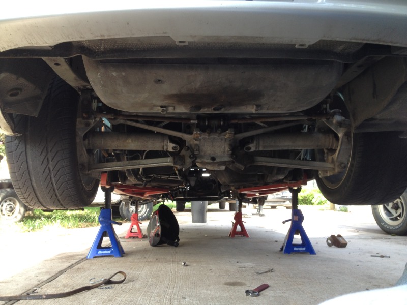
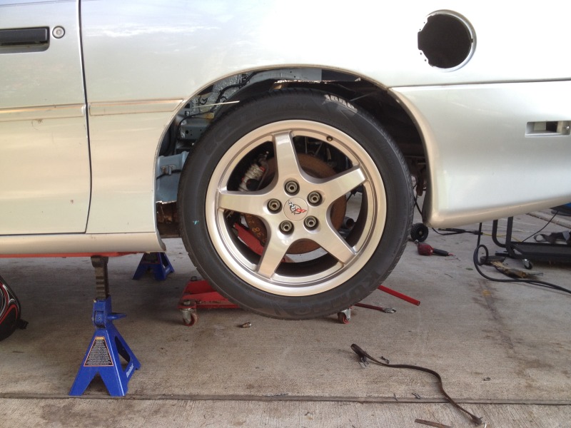
The 18 x 9.5 are nestled pretty well in the wheel-wells Theres around 2-inches of space on all sides!
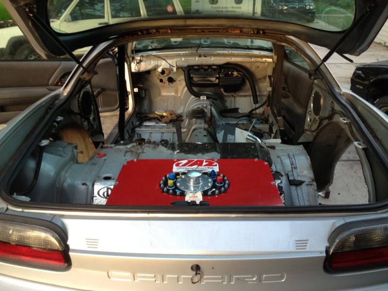
I also got the "fuel cell" sitting in place. Ill start building the box and bulkhead for it when I get some more cash.
Marked for cutting.
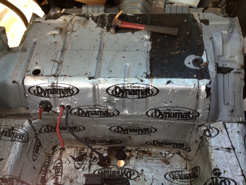
Fuel cell propped in place
There's still the matter of the control-arms and the final gusseting. BUT for the most part its in.The 18 x 9.5 are nestled pretty well in the wheel-wells
Theres around 2-inches of space on all sides!I also got the "fuel cell" sitting in place. Ill start building the box and bulkhead for it when I get some more cash.
Marked for cutting.
Fuel cell propped in place
07-19-2012, 11:09 PM
#53
My birthday just passed, so in the tradition of self entitlement, I went ahead and ordered one of these beauties from blainefab.
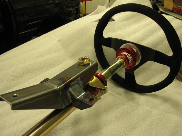
The custom steer-column assembly is a direct bolt-in. I had it ordered at 39inches. With 6-inches of collapsible adjustability for safety. I had it made long to accommodate my 6'10 frame. Now, even with the seat sitting all the way back, the steering wheel sits comfortably over my lap with more foot-box space to boot!
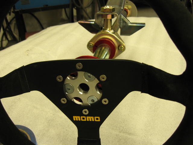
It also comes with a custom hub/wheel adapter to accomodate a horn button (this is a street car, of course) and a Momo model 78 "suede" covered steering wheel. It also has a steering wheel "pull-ring" quick disconnect to make the job of loading and unloading my big *** out of the car easier. (good security too)
No-more having to crouch close to the steering wheel or move my seat forward to grip the steering wheel comfortably. Also, no more wobbly tilt column.
Nice and Solid. This thing should be sturdy as a cemented sign-post.
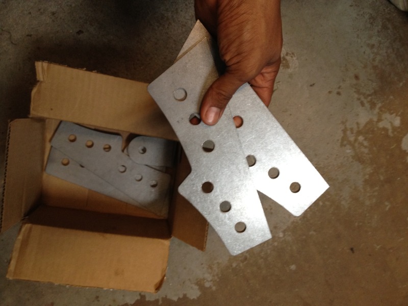
I also finally got my brackets back from CNC. They look really nice.
The custom steer-column assembly is a direct bolt-in. I had it ordered at 39inches. With 6-inches of collapsible adjustability for safety. I had it made long to accommodate my 6'10 frame. Now, even with the seat sitting all the way back, the steering wheel sits comfortably over my lap with more foot-box space to boot!
It also comes with a custom hub/wheel adapter to accomodate a horn button (this is a street car, of course) and a Momo model 78 "suede" covered steering wheel. It also has a steering wheel "pull-ring" quick disconnect to make the job of loading and unloading my big *** out of the car easier. (good security too)
No-more having to crouch close to the steering wheel or move my seat forward to grip the steering wheel comfortably. Also, no more wobbly tilt column.
Nice and Solid. This thing should be sturdy as a cemented sign-post.
I also finally got my brackets back from CNC. They look really nice.

 07-22-2012, 11:36 AM
#55
Those are the modified brackets that you sent me. S & W race cars cut them. Thanks again for the help.
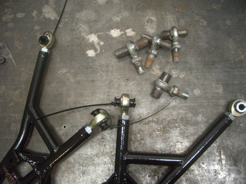
Im going to have to wait a little while before I weld them into place. I have a couple of heim joints on order right now. Ill have to wait until they arrive before I can make anymore progress.
Im going to have to wait a little while before I weld them into place. I have a couple of heim joints on order right now. Ill have to wait until they arrive before I can make anymore progress.
07-22-2012, 05:13 PM
#56
On The Tree
iTrader: (20)
Join Date: Mar 2007
Location: TX
Posts: 126
Likes: 0
Received 0 Likes
on
0 Posts
That steering column/wheel is going to look great in that car man! I'm glad the brackets turned out well to. I would try to go with some UMI rotojoints over heims if you can because of the street use. I can explain further if you like but from experience you will definitely want the rotojoints.
07-23-2012, 05:22 AM
#57
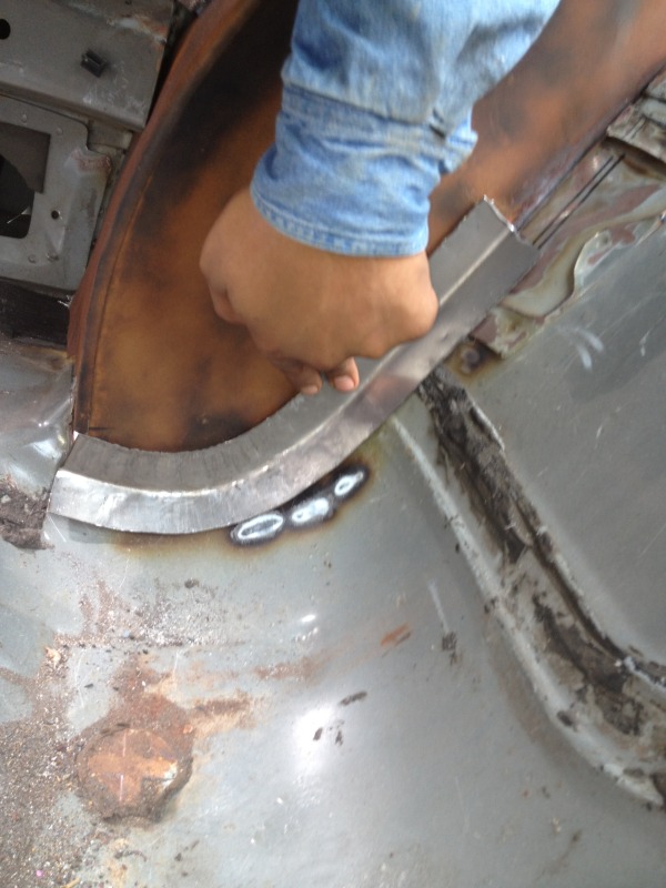
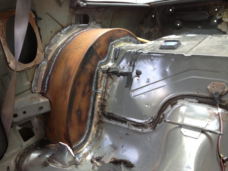
I still need to actually install the engine and trans in order to check for final pinion angle before I finish the C4 IRS install. In the meantime I went ahead and did some sheet-metal work on a "turbo-ls" 3rd gen project car. Its my first time doing sheet-metal/ body work like this. It didn't come out half-bad
(You'll have to pardon the rust. Its been humid as hell lately in Houston)
99-Orange-SS... Roto-joints, huh? Well, I havent actually assembled the trailing arms yet, so Its still do-able. Ill try them out.
(You'll have to pardon the rust. Its been humid as hell lately in Houston)
99-Orange-SS... Roto-joints, huh? Well, I havent actually assembled the trailing arms yet, so Its still do-able. Ill try them out.
07-23-2012, 08:02 AM
#58
That steering column/wheel is going to look great in that car man! I'm glad the brackets turned out well to. I would try to go with some UMI rotojoints over heims if you can because of the street use. I can explain further if you like but from experience you will definitely want the rotojoints.
07-25-2012, 07:51 PM
#59
On The Tree
iTrader: (20)
Join Date: Mar 2007
Location: TX
Posts: 126
Likes: 0
Received 0 Likes
on
0 Posts
If you'd like to find out what they are there is a link on the left side of UMI's website. You could easily incorporate them in the trailing arms. For the camber rods I would suggest calling UMI and giving them the width dimensions of needed and since they custom fab everything in house I'm sure they could accommodate proper inner rods of the joint so they will fit. These joints will provide you with almost no play in the joints like heims, provide you with a joint that is able to be greased without loss of rod strength, and be quiet and last for daily driving use. For the toe rods I'd still stick with some QA1 XM heims.
Your above work looks good to, I'm sure you'll make yours look even better "unintentionally".
Your above work looks good to, I'm sure you'll make yours look even better "unintentionally".