
How Can I Get More Front Wheel Travel?
 04-09-2007, 09:29 PM
#1
Has this topic been discussed before? If so can you please point me in the right direction?
I'm going to repost some info from another thread that went off topic and start a fresh thread here.
I have a 99TA and basically want to be able to tuck the wheels up higher into the fender well. Being lowered I only have 2" of compression travel right now and I like to add at least one more inch.
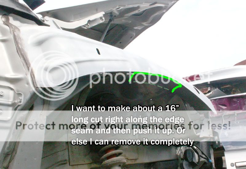
Here is my idea. The green in this pic is the cross section view of the sheetmetal fender. What do you guys think?
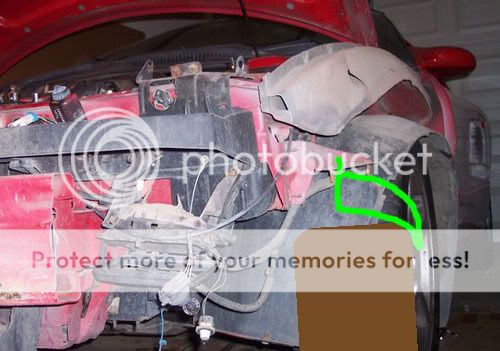
This fender piece doesn't seem to be any kind of important structure or brace, so it looks ok to cut about a 16" long arc and bend in just the top part of it. Now I was told it is structural by Blainefab, trackbird and John_D.
I'm still having trouble actually figuring out the forces involved mainly due to the lack of pictures. I'm going to try to get some in the morning from a salvage yard.
I'm thinking that there must be some race car guys who have already done this modification. Does anyone have any pictures or comments about this?
I'm going to repost some info from another thread that went off topic and start a fresh thread here.
I have a 99TA and basically want to be able to tuck the wheels up higher into the fender well. Being lowered I only have 2" of compression travel right now and I like to add at least one more inch.
Here is my idea. The green in this pic is the cross section view of the sheetmetal fender. What do you guys think?
This fender piece doesn't seem to be any kind of important structure or brace, so it looks ok to cut about a 16" long arc and bend in just the top part of it. Now I was told it is structural by Blainefab, trackbird and John_D.
I'm still having trouble actually figuring out the forces involved mainly due to the lack of pictures. I'm going to try to get some in the morning from a salvage yard.
I'm thinking that there must be some race car guys who have already done this modification. Does anyone have any pictures or comments about this?
 04-12-2007, 01:24 AM
#2
I'm coming up with a plan to remove the sheetmetal "fenders" completely if I want. It will require adding bracing between the firewall and front subframe.
I'm also working on a dropped spindle plan. I'm thinking a 1.5" drop would be good.
I'm also working on a dropped spindle plan. I'm thinking a 1.5" drop would be good.
04-12-2007, 09:45 AM
#3
12 Second Club
iTrader: (5)
Join Date: Aug 2002
Location: Middleville, Michigan
Posts: 1,789
Likes: 0
Received 0 Likes
on
0 Posts
Do you realize the piece you are highlighting in your pictures is plastic right? There's no metal there. The metal is the gray part up higher where the hood closes and the top of the fender mounts to.
04-12-2007, 09:57 AM
#4
I think your looking at the picture wrong.
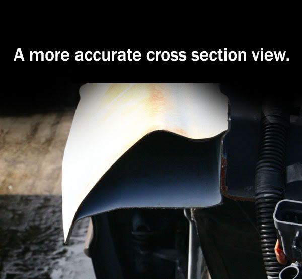
I stated: At the time, that was the only photo I had. Here is an actual cross section view of the sheetmetal "fender".
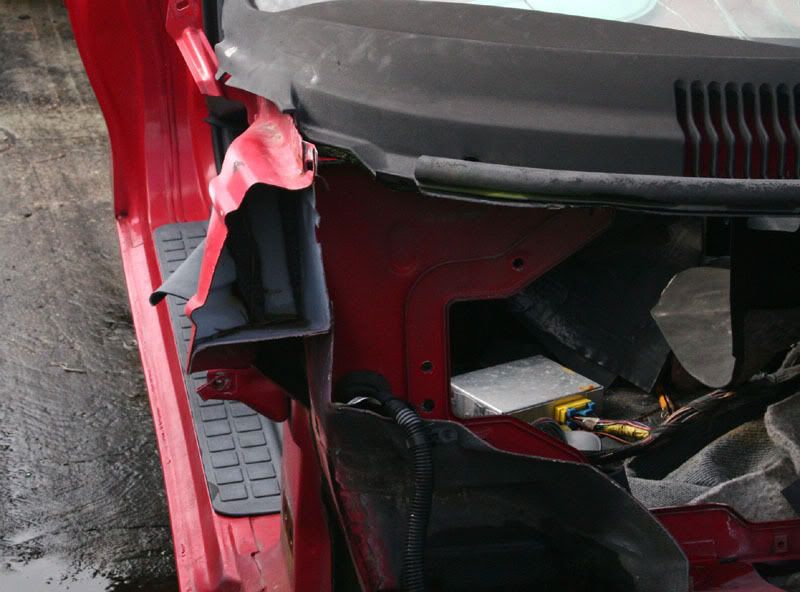
I stated:
Here is my idea. The green in this pic is the cross section view of the sheetmetal fender.
04-13-2007, 08:07 PM
#5
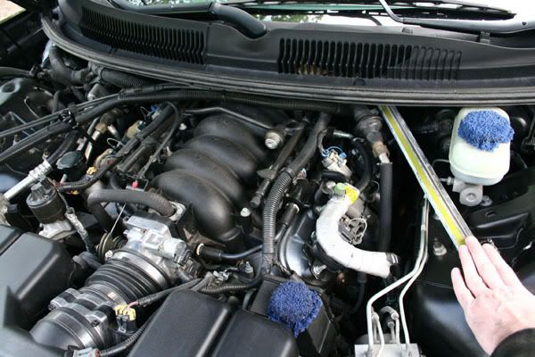
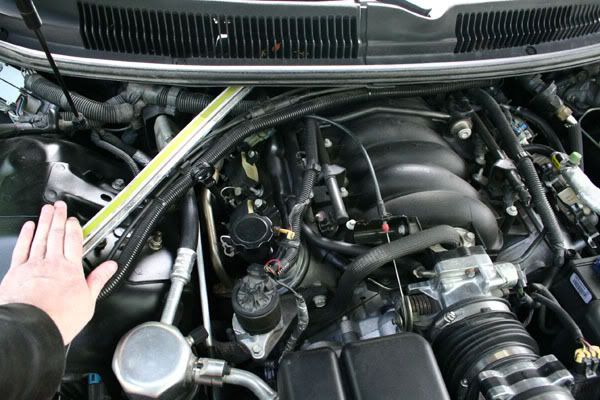
I think I have a way to actually measure the amount of real world flex between the front subframe and the firewall. OK, back when I was measuring the suspension travel I used zipties on the shock rods. I can use the same technique here. I can make my own little telescopic "shocks" out out a steel rod and pipe. I'll get them sized up so they slide together inside one another kind of like the hood shocks. Anyway, I'll attach one end to the firewall and one end to the shock tower then attach the zipties right at the meeting point.
I think making 2 of these and attaching them here would be the best choice.
I'll set the zipties with the car on the ground then lift if from the stock locations behind the front wheels. I'll then see if the weight of the engine causes the distance to expand or not. Then I'll reset them and go do some aggressive driving. Then check to see if the forces in the other direction as well as left/right forces caused the distance to compress.
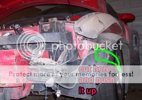
Then the real test. I'll cut into the fender sheetmetal just like I mentioned earlier. About a 16" long arc right above the tire and push the sheetmetal flap all the way up. Then I will repeat these same tests again and see what the actual difference is.
Do you guys think this test would be accurate?
Would my telescopic mounting points be the best choice or should I choose a different location or angle?
I think making 2 of these and attaching them here would be the best choice.
I'll set the zipties with the car on the ground then lift if from the stock locations behind the front wheels. I'll then see if the weight of the engine causes the distance to expand or not. Then I'll reset them and go do some aggressive driving. Then check to see if the forces in the other direction as well as left/right forces caused the distance to compress.
Then the real test. I'll cut into the fender sheetmetal just like I mentioned earlier. About a 16" long arc right above the tire and push the sheetmetal flap all the way up. Then I will repeat these same tests again and see what the actual difference is.
Do you guys think this test would be accurate?
Would my telescopic mounting points be the best choice or should I choose a different location or angle?
04-13-2007, 08:08 PM
#6
Do you guys think I should do a big test like I did with the bumpstops and ride heights? I would only get one shot at this because once I cut the fenders I won't be able to get any more stock measurements.
I could probably make 4 of the telescopic indicators. 2 can measure the up and down movement between the cowl and the shock towers. I believe the pivot point for the front subframe would be near the bottom where it is welded onto the main chassis. So measuring the movement at the top would seem to be the best place to measure.
I could then make 2 indicators to check just the left and right movement between the subframe and the cowl. I could probably best measure this side to side movement with longer devices from the cowl to the front radiator support in a X pattern.
So if you guys finally want some definitive proof about how much slop there is in the subframe to chassis as well as the effects of cutting into the fender wheels to gain suspension travel please let me know. I can add more measuring points if needed. I want to be as thorough as I can.
04-13-2007, 08:09 PM
#7
I want to be as scientific as I can to measure the movement in the front. Making the little telescopic indicators should be cake. Doesn't it make sense to use several so that I can check any and all movement between stock and the cut fenders?
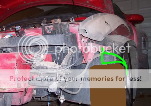
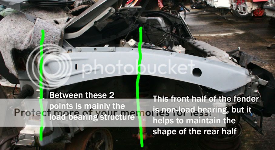
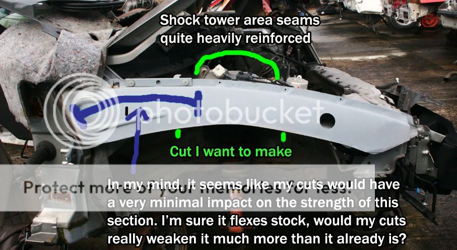
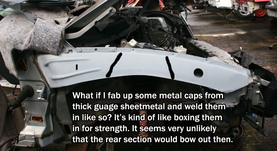
Can we agree about these 2 pics?

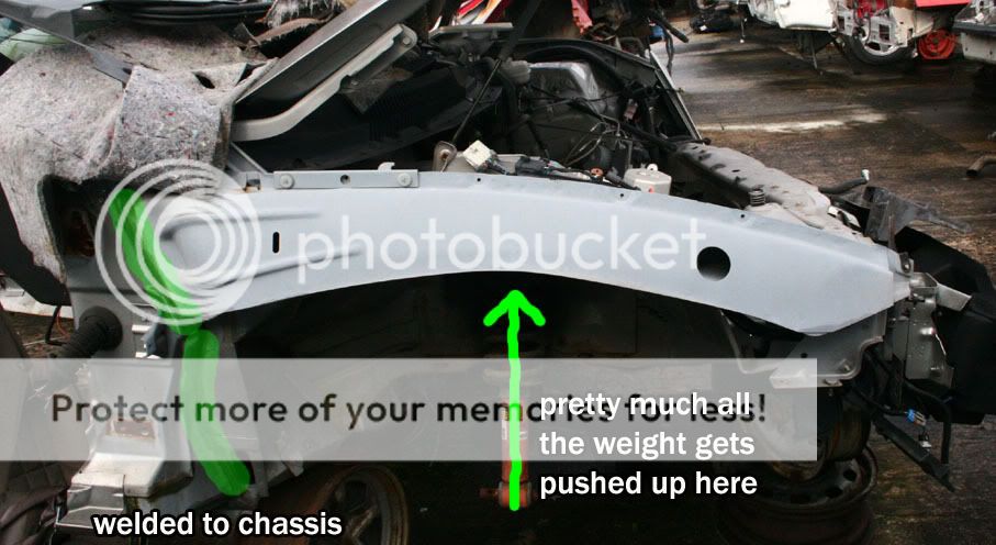
Can we agree about these 2 pics?
Trending Topics
 05-02-2007, 08:47 AM
#11
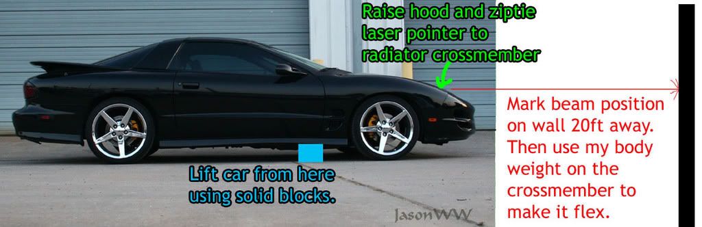
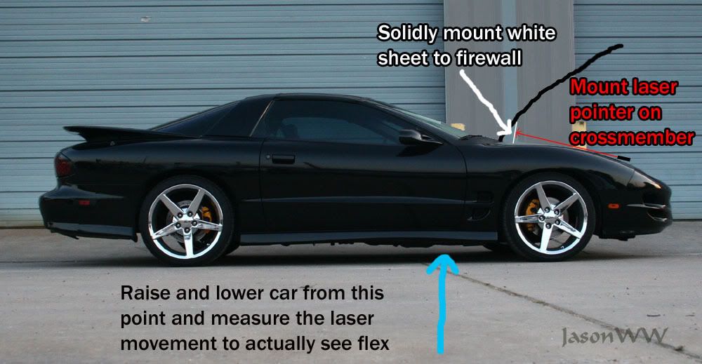
OK, I thought of 2 better ways for me to measure the front subframe flex. Both use a laser pointer. What do you guys think of this? Would it be accurate?
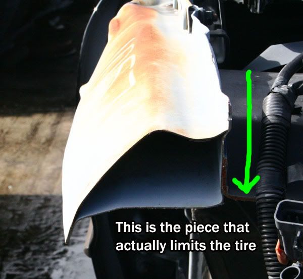
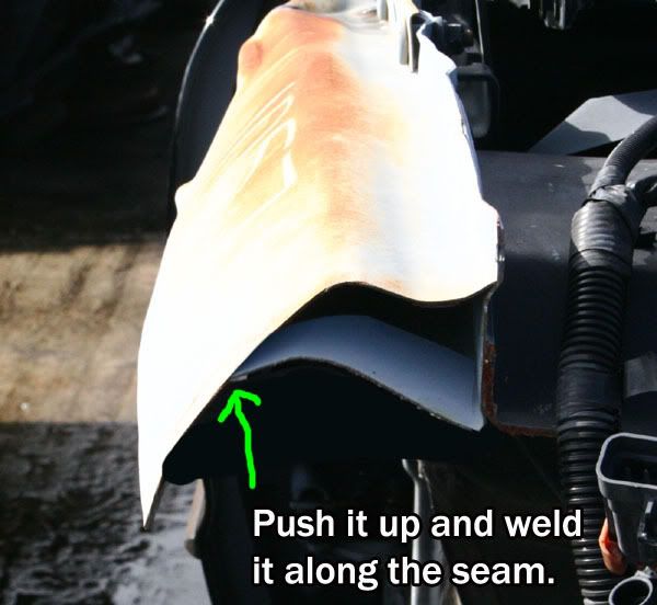
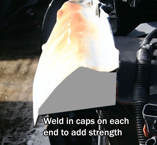
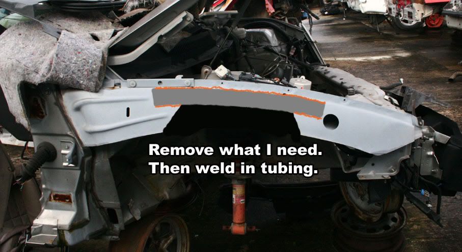
I also thought of 2 ways I can reinforce the fender area I want to cut out. One is pretty labor intensive so I'll show the easier one. Now I think I can do this by raising the car, removing the wheel and then cutting only the bottom rectangle shape out of the arch that the tire needs to move up in. Then I can take some tubing and bend it to match the arc. I can unbolt the plastic fender along the top and space it away from the metal so that the tubing can be welded into place. I'll take care not to let the plastic get very hot as I don't want to hurt it or the paint. I'm not sure about the tubing diameter or wall thickness so I'll probably take it to a fab shop and bend whatever the pro's think are the best size and shape of tubing. It will look like this and will not be seen from under the hood. Do you guys think this should be plenty strong?
One last thing, I want to move the tire up to see how far it will actually go. At first I was thinking I would have to remove one of the spring/shock assemblies and sway bar link so I can manually lift it up. Then I came up with the idea to just knock loose the lower ball joint. I think that would work and let me raise the tire for pics and such. Does that sound like the best way to do it?
05-04-2007, 08:19 AM
#12
I was able to use this method last night.
I ziptied the laser to the radiator crossmember right next to the headlight so it would be closer to the corner. I wanted to minimize any twist in that crossmember. Anyway, I was able to lift the car by both sides simutanously. I measured movement of 3mm on the paper. It's not a lot, but I was just shifting the weight slowly and watching the flex. Based on this I bet the front of the car flexes up and down quite a bit when it hits a bump or a dip at speed. I don't like it. Seeing it flex like that makes me want to add a lot of reinforcement. Side to side loads my have even greater movement, but I have no good way to measure it.
I ziptied the laser to the radiator crossmember right next to the headlight so it would be closer to the corner. I wanted to minimize any twist in that crossmember. Anyway, I was able to lift the car by both sides simutanously. I measured movement of 3mm on the paper. It's not a lot, but I was just shifting the weight slowly and watching the flex. Based on this I bet the front of the car flexes up and down quite a bit when it hits a bump or a dip at speed. I don't like it. Seeing it flex like that makes me want to add a lot of reinforcement. Side to side loads my have even greater movement, but I have no good way to measure it.
05-04-2007, 01:51 PM
#13
This looks like the best way to reinforce it right here. Run tubing through these areas.
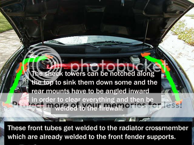
I'll probably add a shock tower brace as well, but since they are premade it's no problem to just add one at any time. If anybody has a better idea to reinforce it, please let me know.
I'll probably add a shock tower brace as well, but since they are premade it's no problem to just add one at any time. If anybody has a better idea to reinforce it, please let me know.
05-04-2007, 03:55 PM
#14
Resident Racing Jerk
iTrader: (1)

Join Date: Dec 2002
Location: sc
Posts: 647
Likes: 0
Received 0 Likes
on
0 Posts

i gotta ask... are you an engineer or going to school to be one? your posts totally remind me of an engineer's thought process/babbling. lol
anyway, what are you wanting to get more travel for? my car is also lowered and it seems fine. not following what you need to do here.
anyway, what are you wanting to get more travel for? my car is also lowered and it seems fine. not following what you need to do here.
05-04-2007, 04:07 PM
#15
TECH Junkie
iTrader: (7)
Join Date: Jul 2005
Location: MA
Posts: 3,934
Likes: 0
Received 0 Likes
on
0 Posts
I was wondering the same thing. I was going to ask you how the convorsation with yourself was going 
I'm just bustin on you by the way, please don't get sensetive by my comment like a lot of people online do
I'm just bustin on you by the way, please don't get sensetive by my comment like a lot of people online do
05-04-2007, 04:55 PM
#16
On The Tree

Join Date: Feb 2004
Location: Houston
Posts: 127
Likes: 0
Received 0 Likes
on
0 Posts
Being a an engineer myself I would be very surprised if Jason is not an engineer. The last picture you posted about the tubing running along the shock towers reminds me immediately of a race car chassis. Forgive me for I have been out of the loop, and I know you want to tuck those wheels up there, but what is your ultimate goal for taking this on? Are you wanting to just slam the thing for looks, are you building a race car, do you just want it to handle better? I am building a GT car out of a 1996 V-6 Camaro and I am planning to tackle this same thing but I am doing it not only for a lower CG, but also for aerodynamic reasons. I am trying to figure out if its possible or worth it to make it a flush-bottom racecar, but considering that is worthless if I cant get the car low enough to build a front valence/air dam...
Anyway SORRY to jack your thread already...what I was getting at is the last picture you show looks like the forward bars of a race car chassis. So let me know what you are up to and we can go from there. You have some great ideas I would just like to know more...sorry again for being ignorant if this is old news
I am just beginning to tear the Camaro apart but build documentation will be coming soon.
05-04-2007, 05:31 PM
#17
From what I understand, I think he just wants to modify the original dseign to have a car that is both low to the ground AND comfortable ride... gonna be amazing if/when he pulls it off.
-Chris
-Chris
05-04-2007, 05:34 PM
#18
Resident Racing Jerk
iTrader: (1)
Join Date: Dec 2002
Location: sc
Posts: 647
Likes: 0
Received 0 Likes
on
0 Posts
i know the issue with my lowered car is more with the k-member, oil pan, headers, exhaust than anything else. i would prefer that it not go any lower when going over bumps and stuff than it already does...
05-05-2007, 04:18 AM
#19
Originally Posted by vtec
i gotta ask... are you an engineer or going to school to be one? your posts totally remind me of an engineer's thought process/babbling. lol
Originally Posted by vtec
anyway, what are you wanting to get more travel for? my car is also lowered and it seems fine. not following what you need to do here.
A few years ago when my suspension was completely stock I made a video tape of my cars suspension travel. Mainly under breaking, but also how much it rocked and swayed. I could clearly see that the front bumpstops were being used fully by simple zipties I added to the shock rods under braking. When I reviewed the video tape I could clearly see that there was a lot more room between the tire and the plastic splash guard, but that the bumpstops were not allowing the tire to move up that high.
I then replaced them with Koni SA shocks and Ground Control 550/160lb springs and tried different ride heights. With 25" fender lips it rode OK as long as the road was smooth. Any kind of bump could be pretty harsh. So I tried 25.75" and that smoothed it out a lot. Right before I got it aligned I decided to go to 26" in the front and rear. This helped even more. So I knew that the more compression travel I had, it would directly effect the ride quality.
I still didn't have much suspension travel in the rear, though. So I did some calculations while measuring the rear shocks internal bumpstops and any other things that may have gotten in the way and found that the factory rear bumpstops were reducing the travel by far too much in my opinion. So I removed the rear bumpstops and added my own to give me an additional 3/4" of compression travel and it was the best move I could have made. With 160lb rear springs and custom bumpstops the ride became much smoother. This is really the motivation to extract even more compression travel from the rear and now some from the front.
Even though my car rides quite smooth, especially for how low it is it can still toss you around if the road is really bumpy or full of low spots. I don't usually see that unless I'm on a dirt road or something, but still, I think that if I can extract a bit more travel out of the front and the rear that the ride will be even better while not losing any performance. In fact I may gain performance because the tire will be able to follow the road better while cornering or braking.
I know all this stuff first hand, so I don't expect many people to understand my wanting to do this. That's OK. I could probably just leave the car alone, but knowing that I can do these mods and make the ride better than it is now just makes me want to do them even more.
This is the kind of stuff that is fun for me. It gets me thinking and I end up learning more and more as time goes on. I've already learned a lot and I hope to learn more.
Keep in mind, if Sam Strano hadn't experimented with the Bilstein shocks years ago when he was racing and when the rules only allowed you to revalve them (not run adjustable shocks) he probably wouldn't be the big shock guru he is today.
05-05-2007, 04:28 AM
#20
For some of the other questions:
I'm actually glad you guys asked about the car touching the ground. I was pretty sure that would not happen, but it got me thinking so I did some measuring just to find out what the low spots were and by how much.
My fender heights are 26" front and 27" rear keeping in mind my rear tires are a bit taller than stock. The clearances are such:
K-member and trans crossmember = 5"
my slightly trimmed down front air dam = 5.25"
muffler = 6"
front fender forward edge = 7"
front fender rear edge that hangs down with the 2 bolts in it = 6"
rear fender forward side skirt = 6"
rear fender rear edge = 8"
front nose of car = 10"
The only really low parts are the stock drivers side cat and Y pipe = 3.8"
Keeping in mind I have 2" travel in the front that means that on a big dip at speed my y-pipe may get within 1.8" of touching the graound. I'll soon add some full length headers (not SLP) and I'll probably just replace both front floor pans. I'll raise the drivers side slightly and lower the passenger a couple inches. Then make a Y with some large diameter tubing, say 5" or 6" if I can find it and then flatten it down to about 3" and put it together myself. Once finished I can send it out for a jet hot coating. I don't plan to run cats, but I'll worry about that later.
Hopefully I can have the entire exhaust clear 5". That seems to be the magic number for a street car as I pretty much don't scrap on anything now. Most drive-on lifts need 5", the new GT40 has 5", my driveway clears at 5", etc... So that's what I'm shooting for.
BTW, I also checked the upper a-arm clearance. On my car at least, when the tire is touching the metal fender there is right at 1" of room left for the arm to move up. The shock towers are specifically shaped to match the a-arm/balljoint shape.
PS. I plan to keep my car at it's current ride height.