
Has Anyone Converted to a Short Front Spindle?

Thread Starter

Joined: Sep 2004
Posts: 6,814
Likes: 3
From: Hou. TX.
This is the geometry I'm thinking is the best. Flat LCA and the UCA at an angle. Under cornering and body lean, the outside wheel creates negative camber and the inside wheel creates positive camber which is exactly what you want.

Last edited by JasonWW; Feb 18, 2011 at 02:15 PM.
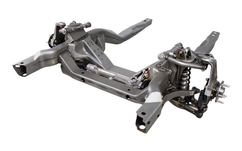
And that Griggs setup pictured above is a pretty nice setup.
Last edited by fast377; Feb 21, 2009 at 10:51 PM.

Thread Starter
Joined: Sep 2004
Posts: 6,814
Likes: 3
From: Hou. TX.
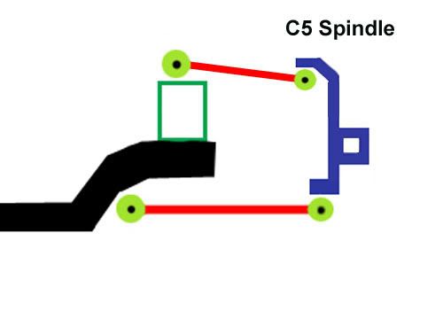
Here it is with the C5 spindle. When cornering hard you will get get no extra camber. In fact, you my loose a little. That's not what you want in a handling car. Do you see what I mean?
Do you know the name of the company that makes the C5 UCA's? They look pretty good. I notice they mount like C4 arms (old style). The C4 used shims on the UCA to adjust the suspension. The C5 had a fixed UCA and instead used slots for the LCA (like the F-body) to adjust things. I like the idea of having both so I have extra adjustability.

Last edited by JasonWW; Feb 22, 2009 at 11:45 AM.
Okay, I see what you are saying...I misunderstood. I haven't actually taken those measurements, so I don't know. I'm hoping to get my car down to one of those guy's shops sometime next month so I can get some things ironed out. Have you measured it out? If you have, is there no way to reduce the size of that green box in your pic?
If the uca mount height could be shortened, the you could get some of that caber angle back. Is there room to mount the uca to the side of the frame rail like the Griggs setup?
The fabricated uca in the picture I posted is from Detroit Speed. They are a local outfit specializing in first gen stuff. The setup in that pic allows the use of 11" wheels without fenderwell mods on the first gen. With the fenderwells removed...how wide do you want to go?
Thread Starter
Joined: Sep 2004
Posts: 6,814
Likes: 3
From: Hou. TX.
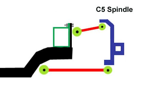
Since headers stay to the inside of these rails, there are numerous ways to modify them. I'm sure the rails can be notched higher so that the UCA can mount in position 3.
If you want to leave the frame rails stock, then you can mount the UCA in position 2, but it makes for a short arm. The shorter it is, the more extreme the ball joint angle gets at the suspension limits.
Since I'm doing an air suspension, I want to have a large range of motion without massive geometry changes. That's why I want the longer upper arm.
I think I need an actual spindle to make more accurate measurements, but I don't want to waste my money on the wrong one. I have measurements, so maybe I can make a fake spindle to use just for measurements. Then I can take actual pictures so everyone can see.
Last edited by JasonWW; Feb 22, 2009 at 02:00 PM.
Thread Starter
Joined: Sep 2004
Posts: 6,814
Likes: 3
From: Hou. TX.
This took me forever to make, but here you go. Front veiw on top, side view on bottom.
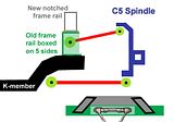
The 5 sided box that the arm would mount to can be heavier gauge and welded to the K-member. Then the frame notch can bolt to it.

The 5 sided box that the arm would mount to can be heavier gauge and welded to the K-member. Then the frame notch can bolt to it.
Last edited by JasonWW; Mar 5, 2011 at 05:42 AM.

I'm with you now. I was picturing things differently.
I keep forgetting you want lots of travel. I don't...the way I'm going, I need very little travel.
What if you made a plate that got sandwiched between the k-member and the frame rail. The uca could mount to that. You wouldn't get the length you want, but wouldn't the extreme angle give you a travel radius like you want?
I like the idea of the uca "pocket" I just don't know if you would lose structural integrity or not.
Last edited by fast377; Feb 22, 2009 at 03:06 PM.
Thread Starter
Joined: Sep 2004
Posts: 6,814
Likes: 3
From: Hou. TX.
Check out how short this GT40 UCA is.

Last edited by JasonWW; Mar 5, 2011 at 05:43 AM.
From your picture in post 60...what if you took mount #1 and moved it further inside. That would give you a longer arm...but you would have to implement some sort of travel limiter so that at full droop, you don't run into binding. Koni makes some shocks with built in limiters. Might be an "easier" route.
I figured for my setup, I would do basically like you said. Try and use either stock C5 stuff or rod end/threaded rod stuff to keep costs down. And yea, 4" is about all I need.
I figured for my setup, I would do basically like you said. Try and use either stock C5 stuff or rod end/threaded rod stuff to keep costs down. And yea, 4" is about all I need.
Thread Starter
Joined: Sep 2004
Posts: 6,814
Likes: 3
From: Hou. TX.
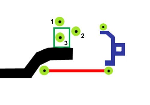
Here is what I meant.
Keep in mind that these drawings are not super exact. Plus the C5 spindles have the upper ball joint further out than the C4 spindles.
Is there any reason you like the C5 spindles over the C4? It looks like the C4 ones are more similar to the F-body spindle.
Keep in mind that these drawings are not super exact. Plus the C5 spindles have the upper ball joint further out than the C4 spindles.
Is there any reason you like the C5 spindles over the C4? It looks like the C4 ones are more similar to the F-body spindle.
Last edited by JasonWW; Feb 22, 2009 at 03:35 PM.
Thread Starter
Joined: Sep 2004
Posts: 6,814
Likes: 3
From: Hou. TX.
From your picture in post 60...what if you took mount #1 and moved it further inside. That would give you a longer arm...but you would have to implement some sort of travel limiter so that at full droop, you don't run into binding. Koni makes some shocks with built in limiters. Might be an "easier" route.
Last edited by JasonWW; Feb 22, 2009 at 03:54 PM.
Thread Starter
Joined: Sep 2004
Posts: 6,814
Likes: 3
From: Hou. TX.
Well, I just won a bid on a short C4 spindle. The whole sha-bang, actually.
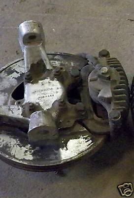
I just stocked up on cutoff wheels to remove the shock towers, then I'm going to just chill until it comes in. Then I'll see exactly what's what.
I just stocked up on cutoff wheels to remove the shock towers, then I'm going to just chill until it comes in. Then I'll see exactly what's what.
I love how you come up with these pictures of hacked up cars...makes me smile . Not much room to come in on the frame at all. Looks like your "pocket" setup might work best for you.
Good deal on the C4 uprights. I think they are real similar to the ATS pieces. They must be an early model...single piston clipers and no abs provision. The should serve their purpose though.
I just picked the C5 stuff because it's readily available, somewhat new, and already has stuff engineered for it (like big brake kits and stuff).
While you are waiting for your C4 stuff to come, I'll try and get some C5 measurements.
. Not much room to come in on the frame at all. Looks like your "pocket" setup might work best for you.Good deal on the C4 uprights. I think they are real similar to the ATS pieces. They must be an early model...single piston clipers and no abs provision. The should serve their purpose though.
I just picked the C5 stuff because it's readily available, somewhat new, and already has stuff engineered for it (like big brake kits and stuff).
While you are waiting for your C4 stuff to come, I'll try and get some C5 measurements.
Thread Starter
Joined: Sep 2004
Posts: 6,814
Likes: 3
From: Hou. TX.
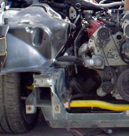
 It's hacked up because I'm doing a front breather conversion (done actually) and flipping the stock radiator the other direction.
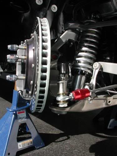
The one problem we'll both have is the steering arm. The C4-C6 had the steering racks much higher than the f-bodies. We are going to need either a long bumpsteer kit or else some bolt on steering arms that lowers the tie rod mount.
You can see the bolt on arm in these pics.
Last edited by JasonWW; Mar 5, 2011 at 05:56 AM.
Thread Starter
Joined: Sep 2004
Posts: 6,814
Likes: 3
From: Hou. TX.
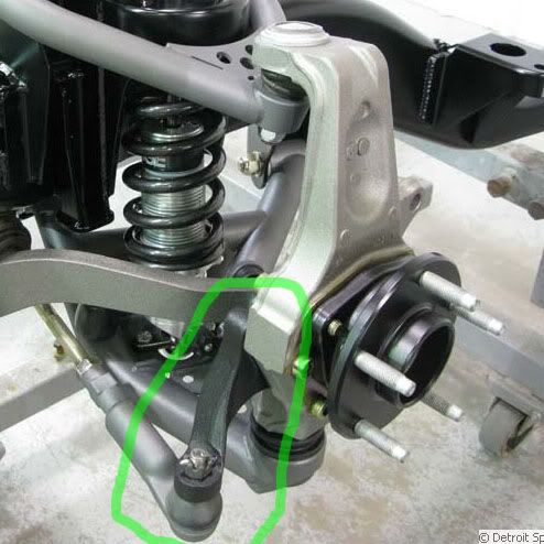
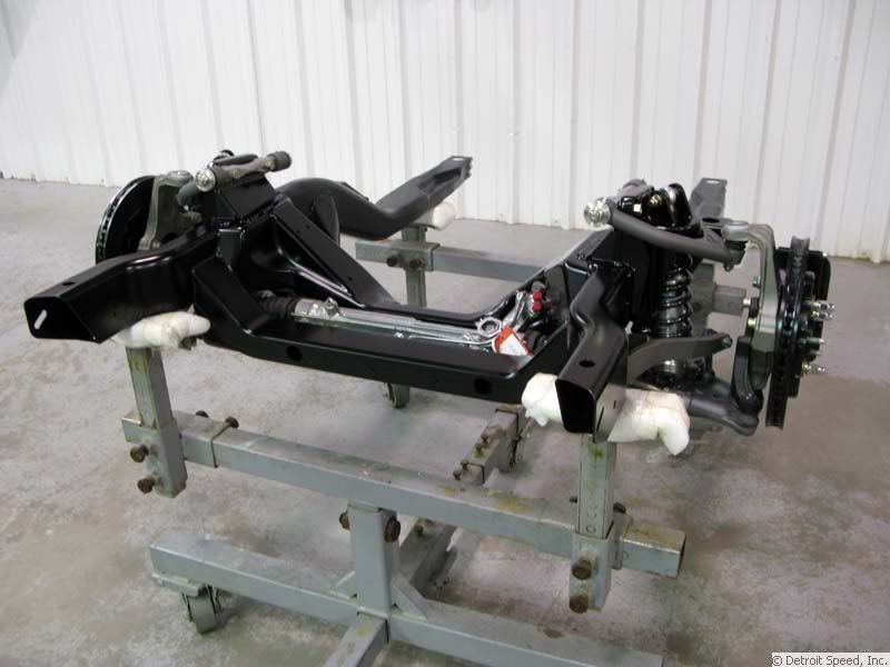
In looking at the Detroit Speed website I found a 69 camaro they did with C4 spindles. They cut the stock steering arm off and used a bolt on unit that lowered it. This is what we will need to do.
Thread Starter
Joined: Sep 2004
Posts: 6,814
Likes: 3
From: Hou. TX.
Here's a nice pic of a 69 camaro. Notice that the steering rack is under the engine, just like in the f-body. That is why they run those lowered, bolt-on steering arms. I wonder if they will sell the arms seperately? Hmmm.
Last edited by JasonWW; Mar 5, 2011 at 05:59 AM.
i swear you're on drugs, haha. you think up some of the most off the wall stuff.
dude props on being different and thinking outside of the box for sure. this could be pretty sweet if done right.
dude props on being different and thinking outside of the box for sure. this could be pretty sweet if done right.
Thread Starter
Joined: Sep 2004
Posts: 6,814
Likes: 3
From: Hou. TX.
I want to see if these shorter spindles will take the cheaper CTS-V 4 piston calipers.
Do you have any idea if the f-body hubs will bolt into the C4 spindles? The hubs look like the same shape. I won't be running ABS so that's no big deal to me.