Any GM tech's or folks with AllData able to pull relay wiring diagram for 2008 vette?
 06-21-2012, 08:41 AM
#1

Low beams stopped working. Light sensor is still working as when I command them off the DIC reads "headlamps suggested". Tail lamps/running lamps come on as well, just doesn't fire up the HID low beams. Went through the procedures to check the control circuit and relay, but I believe the problem might be within the fuse box itself.
The control circuit wire should drop ground to the M2 prong of the low beam relay in order to activate the low beams. If I check continuity on the wire when it should be grounded it goes back and fourth from no continuity to showing some continuity and back. If I jump that prong of the relay straight to ground the HID's come right on as they should.
I pulled the fuse panel apart and found that I have continuity between M2 (relay 47) on the top side of the fuse panel and both pin F1 of connector C3 and pin B1 of connector C1. I don't know which of these are the correct wire and/or why they are somehow internally connected. That is the only other pin that F1 has continuity with.
If anyone could pull up the underhood fuse/relay wiring diagram it would be a huge help. Once I know a: if these wires should be connected, and b: which one is the correct wire, I can decide if the problem is the fuse box itself, the BCM or the wiring between.
Thanks.
 06-21-2012, 08:58 AM
#2
Staging Lane
Join Date: Feb 2011
Posts: 66
Likes: 0
Received 0 Likes
on
0 Posts
2008 Chevrolet Corvette | Document ID: 1894197
--------------------------------------------------------------------------------Hope if this is what your looking for...
WIPER, W/S WASH, LT HI BM, RT HI BM, LT LO BM, RT LO BM, WPR DWELL, WPR/WSW Fuses, and HIGH BEAM, LOW BEAM, WIPER RUN/ACC, WIPER ON/OFF, WIPER HI/LO Relays
--------------------------------------------------------------------------------Hope if this is what your looking for...
WIPER, W/S WASH, LT HI BM, RT HI BM, LT LO BM, RT LO BM, WPR DWELL, WPR/WSW Fuses, and HIGH BEAM, LOW BEAM, WIPER RUN/ACC, WIPER ON/OFF, WIPER HI/LO Relays
06-21-2012, 09:15 AM
#3
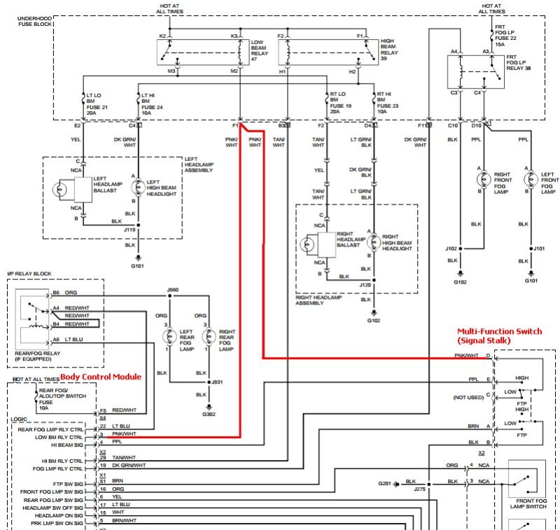
Okay. I found this, but it doesn't seem to explain why I am getting continuity between F1 on the C3 side of the fuse panel and B1 on the C1 side of the connector. According to this diagram that I found on a "freebie" alldata type site, the ground either comes from the BCM or it comes directly from the turn signal stalk (multi-function switch). But either way they both look to come together BEFORE pin F1. I looked through a bunch of diagrams and cannot seem to find what B1 in the C1 connector is.
06-21-2012, 10:33 AM
#4
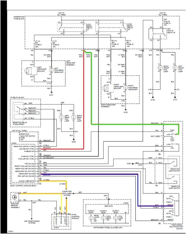
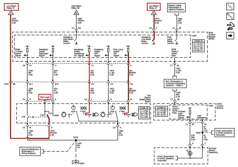
here is the complete diagram for the head lights. after examining it further it seems the body control module is in charge of firing up the head lights both on auto or if you manually turn them on. if on auto it uses the sun sensor through the serial data link into the bcm (yellow line), if on manual it should use pin 15 (blue line) to tell the bcm to force the lights on. what was throwing me off was the green line, however i believe that is used for the "flash to pass" feature. not exactly sure what the wiring diagram is showing there, but it looks like it is used to determine if it is flash to pass or high beams (i am not sure on this however). still have no idea why pin b1 on connector c1 is internally connect to f1 on c3 however since i don't know what b1 on c1 is.
06-21-2012, 10:44 AM
#5
Launching!
iTrader: (13)
Join Date: Jul 2004
Location: fort worth texas
Posts: 269
Likes: 0
Received 0 Likes
on
0 Posts

i couldnt really understand what all youve done,
but i would start with checking power and ground at the light or ballast if you dont have any power go back to the relay (47 low beam) and check you should have battery voltage a two pins and ground on one with lights off, that if the realy works will then be batt power.
The other termianl will be grounded by the bcm so keep either a meter or test light to voltage and see if it grounds when you manually turn on the lights
06-21-2012, 10:56 AM
#6
according to a buddy:
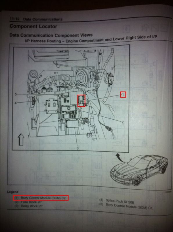
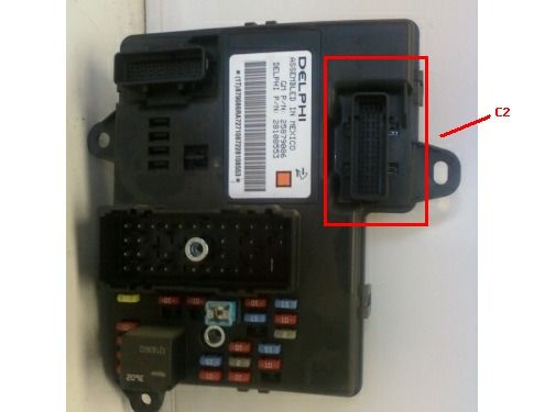
interesting. this is making me believe the problem must be the body control module. i'll check it when i get home. if i apply ground to pin 15 on the C2 BCM connector it should ground pin 3 on the c2 BCM connector which should ground pin F1 on the C3 fuse box connector which should ground pin M2 on relay 47. otherwise i'll check and see if pin 15 is getting a ground signal from the multifunction switch in the first place.
interesting. this is making me believe the problem must be the body control module. i'll check it when i get home. if i apply ground to pin 15 on the C2 BCM connector it should ground pin 3 on the c2 BCM connector which should ground pin F1 on the C3 fuse box connector which should ground pin M2 on relay 47. otherwise i'll check and see if pin 15 is getting a ground signal from the multifunction switch in the first place.
06-21-2012, 11:00 AM
#7
i couldnt really understand what all youve done,
but i would start with checking power and ground at the light or ballast if you dont have any power go back to the relay (47 low beam) and check you should have battery voltage a two pins and ground on one with lights off, that if the realy works will then be batt power.
The other termianl will be grounded by the bcm so keep either a meter or test light to voltage and see if it grounds when you manually turn on the lights
but i would start with checking power and ground at the light or ballast if you dont have any power go back to the relay (47 low beam) and check you should have battery voltage a two pins and ground on one with lights off, that if the realy works will then be batt power.
The other termianl will be grounded by the bcm so keep either a meter or test light to voltage and see if it grounds when you manually turn on the lights