


first time header builder some helpfull hints?
well tomorrow i will be beginning my header setup in my 73 nova tom and just wanted some helpful hints on building them. i fixed the collector today i figure i will start with the farthest cylinder port from the collector and work my way in to the closest port.
so any helpful hints. like using a template or measuring would help
so any helpful hints. like using a template or measuring would help
I've built a few sets for cars and airplanes. Here are some of my tricks-
-Get the flanges from GM. You can't get them water-jet cut for less than GM charges
-Put the collector where you want it and then start building the header between the flange and the collector.
-Make a jig to cut the mandrels. I made one to fit my bandsaw that would cut the tube square at any angle.
-Cut your bends square (see note above) You can also use a piece of paper and a marker to make a mark and cut them square, but it is kind of tedious
-An inexpensive wood bandsaw can be converted to cut metal by installing a jack shaft to slow it down. The old iron frame ones are the best to convert. I have an old cast-iron Delta that I've got about $100 in. Get a bimetal blade for it
-Buy mandrel bends with several different radii (sp?) to ease fabrication.
-Use packing tape to hold the cut pieces together before you weld them so you can do trial fits
-Buy the tube sleeves that Hooker sells to align each pipe joint together. You don't have to back-purge or use a filler rod and it makes a very clean tig weld
-Tack with the MIG and weld with the TIG
-If you can't afford a slip on collector (and who can) have a four-leaf clover design water jet cut with a material width of about 3/16 to 1/4" then weld the tubes to that, then the collector to that. It is almost impossible to get the collector to seal up without doing this, and welding inside the collector is a huge pain in the ***. If you think your motor is so sh*t-hot that one of those pointy thingys in the flow path to help the dump loss into the collector would make a difference, this techniqe makes it really easy to weld one on.
-Tig weld the tube joints. Mig weld the tubes to the flange to create a generous weld fillet - you will have a lot less cracking problems.
-leak check each completed tube before you weld them into the collector and flange. An old bicycle inner tube cut in half and hooked on to each end of the individual tube with a hose clamp works well. Pressurize with shop air through the bicycle stem. A little dish soap in a spray bottle works well for finding pinholes
-If you weld an O2 boss on, make sure the sensor clears other components (don't ask how I know)
-The Techline coatings work pretty good and are much cheaper than ceramic coatings. Cure them on the engine, not in your significant other's oven, or you will have a really big mess on your hands (again, don't ask me how I know)
If you want to see some photos, let me know and I'll gin some up.
Phil
wow thanks phil..
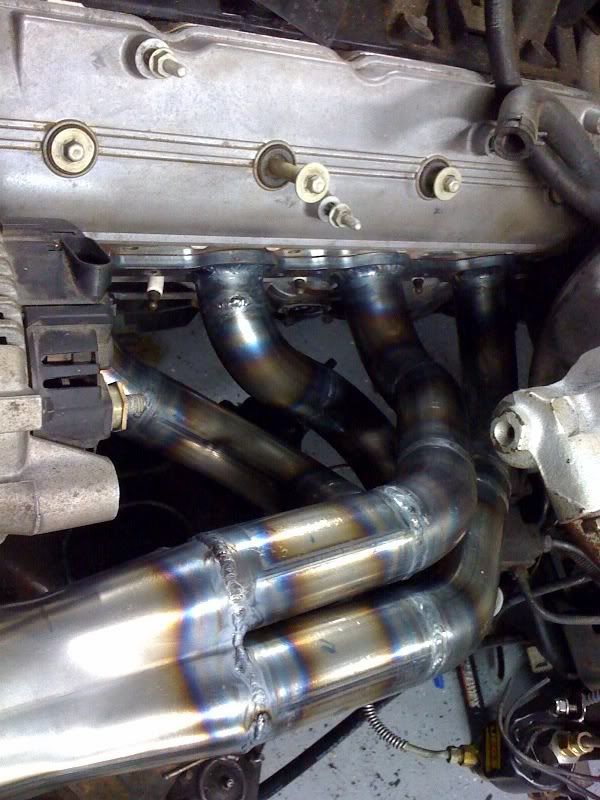
this is what i came up with for the drivers side. now i didn't final weld it yet i got one little hole to fill in the rear tube got a little over zealous with the tig pedal.
Trending Topics
well i plan to coat these and then wrap them with header wrap. if i must make a heat shield i will that's not a problem. here is the final product
 i still need to cut the collector down and fit the vband on.
i still need to cut the collector down and fit the vband on. LS1 Tech Stories
The Best V8 Stories One Small Block at Time

6 Gifts Neither Your Dad Nor Grad Will Shove Into the 'Trinket Drawer'
Brett Foote
Topdon ONE vs. Artidiag 800 BT2: Which is the Diagnostic Tablet For You?
Pouria Savadkouei
Gas Monkey Built a 6-Wheel Ferrari Testarossa With a Corvette LT4 Engine
Verdad Gallardo
7 Most Reliable High-Performance Engines GM Has Ever Built
Verdad Gallardo
Amazing '71 Camaro Restomod Is Modern Muscle Car Under the Skin
Verdad Gallardo
6 Common C5 Corvette Failures and What's Involved In Repairing Them
Pouria Savadkouei
Retro Modern Bandit Pontiac Trans AM Comes With Burt Reynolds' Autograph
Verdad Gallardo
Top 10 Greatest Cadillac V Series Performance Models Ever, Ranked
Pouria Savadkouei
Top 10 Most Powerful Chevy Trucks Ever Made!
im getting ready to build some headers for the GXP this coming winter and am looking for any tips or tricks you guys have whare to get tubing, figuring out primary size, welding tips, and just other things to overlook. this thread has been helpfull so far
GXP comes with an ls4 makes 303 hp stock at the flywheel with a fairly broad curve on it ill put up my stock dyno i was thinking a 1 3/4 or 1 7/8 primaries but traction is an issue with these cars so losing some torque down low for high end power would not be all bad

thanks guys
GXP comes with an ls4 makes 303 hp stock at the flywheel with a fairly broad curve on it ill put up my stock dyno i was thinking a 1 3/4 or 1 7/8 primaries but traction is an issue with these cars so losing some torque down low for high end power would not be all bad
thanks guys


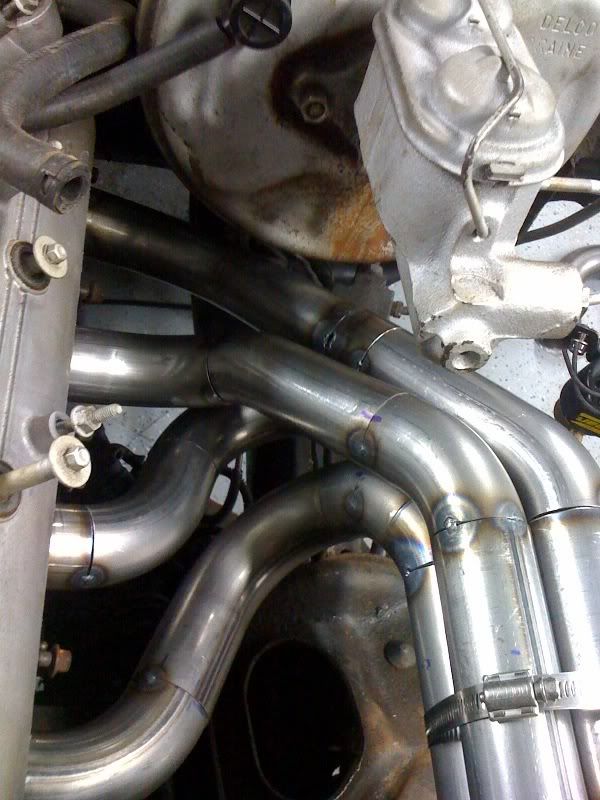
Here is a shot of the collector.
Imagine a four leaf clover cut-out in .25" steel, then a hole punched in the middle of each leaf. Insert the primary tubes inside each of these holes and weld from the inside after trimming the primaries flush.
Slip the collector on over the clover shape and weld all around - no leaks
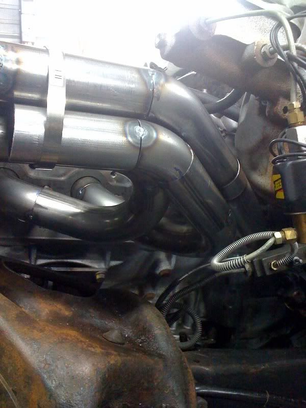
This is what black Techline looks like. You can get other colors too.
(Sorry, the car hasn't been cleaned from the last trip out)

I like vbands. These I salvaged from a junkyard that had a bunch from a food processing facility- I jet cut some soft copper sheet to use as gaskets and no exhaust leaks.

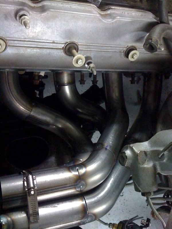
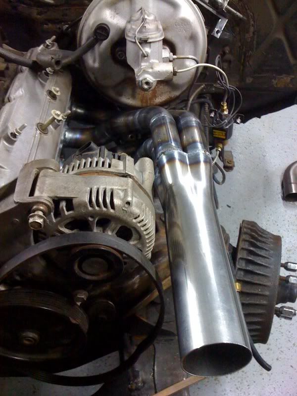
This is a GM header flange. Note the wide fillet on the flange to tube

This is a top down look at the driver's side header. I tried to make them about the 33" primary tube length and equal volume - they are within about 5-10% but it probably doesn't make any difference with the turbo

This is a view of the whole thing and the turbo

This a view from the *** end. The turbo is suspended from the chassis so that the header system could be as light as possible. (the motor mounts are solid) I've beat the hell out of it for three seasons now and no problems so far.
All together I have about $240 in this set, including the water jet pieces but not the coating. It is all mild steel and it isn't coated inside (everytime it starts I make sure it warms up and there is no water in the tubes)
Let me know if there are any more details you'd like to see
Imagine a four leaf clover cut-out in .25" steel, then a hole punched in the middle of each leaf. Insert the primary tubes inside each of these holes and weld from the inside after trimming the primaries flush.
Slip the collector on over the clover shape and weld all around - no leaks
This is what black Techline looks like. You can get other colors too.
(Sorry, the car hasn't been cleaned from the last trip out)
I like vbands. These I salvaged from a junkyard that had a bunch from a food processing facility- I jet cut some soft copper sheet to use as gaskets and no exhaust leaks.
This is a GM header flange. Note the wide fillet on the flange to tube
This is a top down look at the driver's side header. I tried to make them about the 33" primary tube length and equal volume - they are within about 5-10% but it probably doesn't make any difference with the turbo
This is a view of the whole thing and the turbo
This a view from the *** end. The turbo is suspended from the chassis so that the header system could be as light as possible. (the motor mounts are solid) I've beat the hell out of it for three seasons now and no problems so far.
All together I have about $240 in this set, including the water jet pieces but not the coating. It is all mild steel and it isn't coated inside (everytime it starts I make sure it warms up and there is no water in the tubes)
Let me know if there are any more details you'd like to see

And one more thing you asked about..............
There is no fixture per-se.
I fab'd the bifurcated turbo secondary tube first, then hung it in the chassis. Then I trimmed the collectors and v-banded them to the turbo secondary pipe. They could rotate around the center axis, but the flange location was fixed.
Put the GM flange on the motor, then built the primaries to connect the two.
The 2-1 turbo tube is symetrical, as are the header primary tubes from side to side. The cylinder head stagger front to rear is taken up by a longer collector secondary on one side
No I didn't.
I believe I mentioned that I used some alignment rings that Holley sells that puts a thin backup ring inside the tube and a little burn-down ring between the joint. No filler is required and no back gas either. Makes a nice joint.
If anybody is interested I'll get the part number for the rings.
Phil

TECH Regular
Joined: Sep 2008
Posts: 425
Likes: 1
From: Scottsdale, Arizona
No I didn't.
I believe I mentioned that I used some alignment rings that Holley sells that puts a thin backup ring inside the tube and a little burn-down ring between the joint. No filler is required and no back gas either. Makes a nice joint.
If anybody is interested I'll get the part number for the rings.
Phil
I believe I mentioned that I used some alignment rings that Holley sells that puts a thin backup ring inside the tube and a little burn-down ring between the joint. No filler is required and no back gas either. Makes a nice joint.
If anybody is interested I'll get the part number for the rings.
Phil
Plus can someone show how they "back gas" for welding tubing?
Thanks in advance
Here's the link the alignment rings I've used-
http://www.holley.com/types/Miscella...Components.asp
I think I last bought them from Jegs or Summit.
You mentioned "back gas" but what I think you want to know about is "back purge", which is a technique of flowing argon behind the weld to prevent the backside of the weld from oxidizing.
To do it you need an argon regulator with two outlets - one to the tig and the other to the back of the work. (I suppose you could use two argon tanks too) Most people would tape up one end of the tube your welding and put a vent hole, then stuff the other end of the argon hose in the other end of the tube with a rag or tape, then fill it full of argon. It has to flow a little to keep the cavity full of argon while you weld.
Be sure that you do this in a well ventilated area - argon can cause you to suffocate if it displaces air that you breath. (the fumes will probably kill you first, but I just thought I'd warn you)
If you can reach the tacked weld joint, there is also a paste you can use as an alternative to back purging that effectively acts as a flux and keeps oxygen out of the weld. You might check with your local welding store.
Hope you found this helpful,
Phil