High Level Technical Information on Ignition Wires / Components
 10-03-2011, 08:51 AM
#1
FormerVendor
Thread Starter

Join Date: Jul 2008
Posts: 77
Likes: 0
Received 0 Likes
on
0 Posts
I felt it would be a great idea to show the thought behind some of our products and the differences from product to product and thought the Advanced Engineering Tech would be a great place to post some of the more detailed information on ignition wires, ignition coils, spark plugs etc.
I would also like to say that I will do the best possible to post information that is accurate and relevant and I would enjoy for others to join the discussion.
Some things I will be talking about are conductor choice, impedances, insulators, skin effect, resistance and the validity of less resistance etc.
I believe a good place to start would be with ignition resistance past the secondary (output) of the ignition coil, which would be the ignition wire and spark plugs.
This area seems to be a very large portion of the equation 95% of the population doesn't understand when it comes to circuit resistance in an ignition system. It should be noted that the wire is typically less then 10% of the total circuit resistance. I guess the best way to show this is with this.
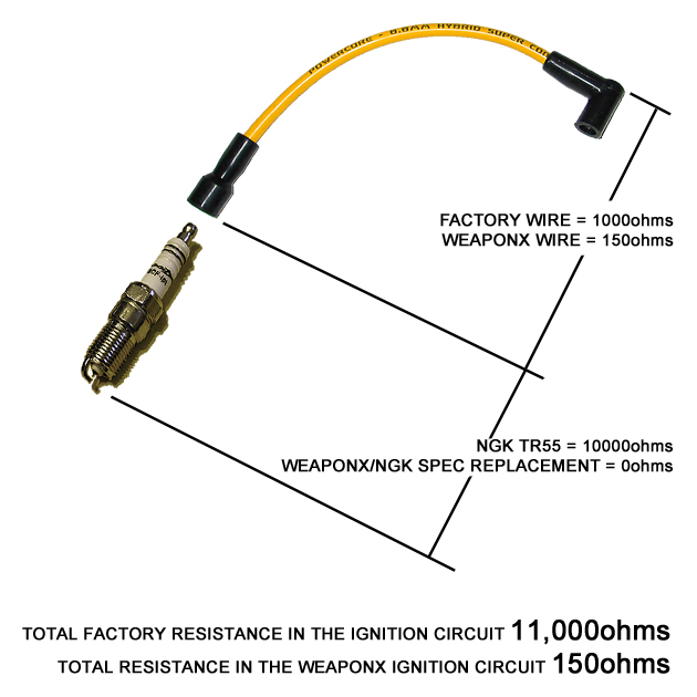
Most people are convinced that they did themselves a favor by lowering the resistance of the wire to 0 or 50 ohms but this means the only thing you accomplished was reducing your circuit resistance from 11000ohms to 10050ohms. Hardly worth an honorable mention. It should also be noted that the smallest resistance found in off the shelf spark plugs is ~5000ohms but ~10000ohms is the most typical.
What WeaponX aimed to complete was to create the lowest 'system' resistance available but still fullfill the requirements of reduced interference levels so what we did was spec 0 ohm spark plugs and wires to accomplish the lowest possible resistance and highest possible output. On a second note, we know many people are die hard NGK fans so we are one of the only companies to offer an NGK brand, zero resistance plug which is equivlant to a TR55 / TR6. We also offer our ExtremeX Iridium with a zero ohm resistance for those looking for the highest output possible. Now, as you can see, the WeaponX setup the total circuit resistance drops from 11,000ohms in most typical applications to 150ohms!
What people seem to be missing is that even with a 0 ohm wire you are still stuck with a 10,000ohm resistance in the spark plug so you have claimed less then 10% of the system resistance back and you can't goto a 0 ohm spark plug because it introduces potential electronic issues in the system.
With the WeaponX system you reduce your system resistance 99.99%! We tried every variation and the highest output and lowest reliable circuit resistance to prevent interference is 150ohms.
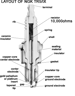
Below is also an internal picture of the NGK TR55. If anybody has a used one, smash it up. What you will find is a chunk of carbon in the middle of the plug used to create resistance. Our spec'd plugs use a solid piece of copper right to the electrode on the other side of the plug allowing for a zero ohm plug.
I will explain more but this is only the very tip of the iceburg. I also plan on showing differences from wire to wire and from our new spiral wound design to the typical spiral wound designs that currently exist.
More on that later.
I would also like to say that I will do the best possible to post information that is accurate and relevant and I would enjoy for others to join the discussion.
Some things I will be talking about are conductor choice, impedances, insulators, skin effect, resistance and the validity of less resistance etc.
I believe a good place to start would be with ignition resistance past the secondary (output) of the ignition coil, which would be the ignition wire and spark plugs.
This area seems to be a very large portion of the equation 95% of the population doesn't understand when it comes to circuit resistance in an ignition system. It should be noted that the wire is typically less then 10% of the total circuit resistance. I guess the best way to show this is with this.
Most people are convinced that they did themselves a favor by lowering the resistance of the wire to 0 or 50 ohms but this means the only thing you accomplished was reducing your circuit resistance from 11000ohms to 10050ohms. Hardly worth an honorable mention. It should also be noted that the smallest resistance found in off the shelf spark plugs is ~5000ohms but ~10000ohms is the most typical.
What WeaponX aimed to complete was to create the lowest 'system' resistance available but still fullfill the requirements of reduced interference levels so what we did was spec 0 ohm spark plugs and wires to accomplish the lowest possible resistance and highest possible output. On a second note, we know many people are die hard NGK fans so we are one of the only companies to offer an NGK brand, zero resistance plug which is equivlant to a TR55 / TR6. We also offer our ExtremeX Iridium with a zero ohm resistance for those looking for the highest output possible. Now, as you can see, the WeaponX setup the total circuit resistance drops from 11,000ohms in most typical applications to 150ohms!
What people seem to be missing is that even with a 0 ohm wire you are still stuck with a 10,000ohm resistance in the spark plug so you have claimed less then 10% of the system resistance back and you can't goto a 0 ohm spark plug because it introduces potential electronic issues in the system.
With the WeaponX system you reduce your system resistance 99.99%! We tried every variation and the highest output and lowest reliable circuit resistance to prevent interference is 150ohms.
Below is also an internal picture of the NGK TR55. If anybody has a used one, smash it up. What you will find is a chunk of carbon in the middle of the plug used to create resistance. Our spec'd plugs use a solid piece of copper right to the electrode on the other side of the plug allowing for a zero ohm plug.
I will explain more but this is only the very tip of the iceburg. I also plan on showing differences from wire to wire and from our new spiral wound design to the typical spiral wound designs that currently exist.
More on that later.
 10-03-2011, 12:20 PM
#2
TECH Enthusiast

Join Date: Sep 2007
Posts: 507
Likes: 0
Received 0 Likes
on
0 Posts
Below is also an internal picture of the NGK TR55. If anybody has a used one, smash it up. What you will find is a chunk of carbon in the middle of the plug used to create resistance. Our spec'd plugs use a solid piece of copper right to the electrode on the other side of the plug allowing for a zero ohm plug.
Sorry if this is part of the upcoming info, but what is the reasoning behind a resistor in the NGK/other plugs? Is it cost or are there other factors?
10-03-2011, 02:50 PM
#3
FormerVendor
Thread Starter
Join Date: Jul 2008
Posts: 77
Likes: 0
Received 0 Likes
on
0 Posts
Originally NGK and others produced their spark plugs with an internal resistance to prevent radio noise interference. This was, to my knowledge, introduced in the 50's. Since then things haven't changed much on the spark plug front. The spark plugs are still used to reduce radio interference but as vehicles became more 'electronic' in nature the resistor in the spark plugs and ignition wires now served a dual purpose, to reduce radio humm (interference) and to keep engine control signals from sensors in the engine bay nice and clean so the ECU could control the engine properly. This is primarily because ignition systems, due to their high voltages, are inherently noisy and can cause quite a bit of feedback and interferences which can confuse electronics in the vehicle. I can explain how this happens in greater detail.
All ignition coils create voltages at the input called flyback voltage (voltages from 150volts to over 1000volts) which are proportional to the output of the ignition coil. These high energy spikes also create magnetic fields surrounding the conductors in the engine bay. The less the interference protection the higher these voltages and the bigger the magnetic fields. In testing with a 0 ohm wire and 0 ohm plug interferences pegged our oscilloscope at over 1 kilo volts at the coil input which is really bad and potentially damaging to the electronics. Also to understand more, some electronics 101, a moving magnetic field introduces electrical signals in adjacent wires. This is the source of confusion in the electronics. Obviously, the higher these interferences the worse the problem gets.
For example
If my ignition wire input runs next to my crank angle sensor wire (5 volt circuit) a high voltage pulse from the ignition wires next to it will generate a co-responding current in the crank angle sensor wire. This is because of something called magnetic coupling between conductors. This is very similar to how transformers work to raise and lower voltages. This essentially has the potential to confuse the computer into thinking the crank has rotated when in fact it was only interference in the system.
Here is a simple picture to help. I should note that I only showed one crosstalk event happening, but as the engine is running these interferences can introduce themselves in adjacent wires all the time, it's just that some can become more confusing then others to the ECU. In this example you can see how the interference is enough to fool the ECU into thinking there was a crank event when infact there was nothing.
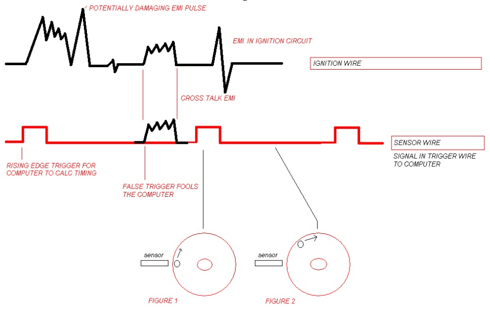
This is also the same reason manufacturers use resistance style ignition wires, to keep these interferences at a minimum.
All that being said, there is a fine line between what is going to be too much interference which can confuse and damage your electronics and too much protection which reduces spark output unnecessarily. Finding that happy balance is the key to a happy ECU and efficient high output ignition events.
If you like I can explain how a spiral wound conductor reduces these interferences and keeps system resistance to a minimum and answer any potential questions you might have about why ignition wires and spark plugs have resistance in them. Just let me know.
10-04-2011, 12:12 PM
#4
FormerVendor
Thread Starter
Join Date: Jul 2008
Posts: 77
Likes: 0
Received 0 Likes
on
0 Posts
OK I will discuss how a spiral wound conductor can effectively control EMI / RFI interferences. I will attempt to give the abbreviated version but if anyone is interested in greater detail just let me know.
The first point. As we know from the previous post, current through a conductor creates a magnetic field. An old science project typically done is the, wrap some wire around a nail and make a magnet trick. The thing to note is that the generated magnetic field, by passing electrical energy through an ignition wire, acts as a power source that doesn't like changes in the flow of current so what it attempts to do is maintain a steady state current through it.
Second point is that because of the effect of keeping current flow nice and steady the wraps of wire also have a tendancy to naturally filter frequencies depending on the strength of the magnetic field created. Because of this many audio enthusiasts should note that low pass filters, meant to only send bass to a subwoofer, typically consist of these wraps of wire called inductors.
A standard torrid inductor
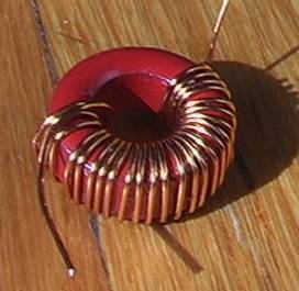
Low frequency filter for subwoofer
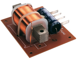
We all know that in an audio system these low pass filters can be exchanged or modified to alter the filtering effect. This will depend on the size of the inductor and how many wraps it consists of. We can somewhat associate the ignition system with an audio system, think of the ignition pulses to the spark plug as the bass and what we are trying to do is minimize the treble output, which would be interference.
In an ignition wire, the more the wraps of wire around the core usually the higher the resistance but with more wraps interference filtering is enhanced in the system. The idea is to make sure that there are enough wraps to effectively control interferences in the system but not so many that there is increased resistance in the system. In our testing, WeaponX PowerCORE ignition wire will only allow 10% more total interference in the system which is well within manufacturer specs. When reducing the amount of wraps resistance drops accordingly BUT it should also be noted that the level of interference increases as a result so finding the right balance is key to a successfully running engine and properly performing electronics.
The first point. As we know from the previous post, current through a conductor creates a magnetic field. An old science project typically done is the, wrap some wire around a nail and make a magnet trick. The thing to note is that the generated magnetic field, by passing electrical energy through an ignition wire, acts as a power source that doesn't like changes in the flow of current so what it attempts to do is maintain a steady state current through it.
Second point is that because of the effect of keeping current flow nice and steady the wraps of wire also have a tendancy to naturally filter frequencies depending on the strength of the magnetic field created. Because of this many audio enthusiasts should note that low pass filters, meant to only send bass to a subwoofer, typically consist of these wraps of wire called inductors.
A standard torrid inductor
Low frequency filter for subwoofer
We all know that in an audio system these low pass filters can be exchanged or modified to alter the filtering effect. This will depend on the size of the inductor and how many wraps it consists of. We can somewhat associate the ignition system with an audio system, think of the ignition pulses to the spark plug as the bass and what we are trying to do is minimize the treble output, which would be interference.
In an ignition wire, the more the wraps of wire around the core usually the higher the resistance but with more wraps interference filtering is enhanced in the system. The idea is to make sure that there are enough wraps to effectively control interferences in the system but not so many that there is increased resistance in the system. In our testing, WeaponX PowerCORE ignition wire will only allow 10% more total interference in the system which is well within manufacturer specs. When reducing the amount of wraps resistance drops accordingly BUT it should also be noted that the level of interference increases as a result so finding the right balance is key to a successfully running engine and properly performing electronics.
10-04-2011, 02:00 PM
#5


excuse me if i ask a stupid qestion. i dont normally post in avanced tech but i lurk here alot.
basically, are you telling us you have found a way to make 0 ohm spark plugs that wont inerfere with radio signals or sensors? or are you guys just working on them?
basically, are you telling us you have found a way to make 0 ohm spark plugs that wont inerfere with radio signals or sensors? or are you guys just working on them?
10-04-2011, 02:21 PM
#6
FormerVendor
Thread Starter
Join Date: Jul 2008
Posts: 77
Likes: 0
Received 0 Likes
on
0 Posts
Yes, you are correct, we have figured out a way to make 0 ohm spark plugs work without any issues. You can use a zero ohm spark plug as long as you use our PowerCORE ignition wire. The PowerCORE wire is developed to take advantage of a 0 ohm spark plug and reduce circuit resistance 99.9% across all GM applications.
We basically started from the ground up and developed a wire that delivers the sweet spot for low resistance, low interference and high output.
Trending Topics
10-04-2011, 02:56 PM
#8
FormerVendor
Thread Starter
Join Date: Jul 2008
Posts: 77
Likes: 0
Received 0 Likes
on
0 Posts
- slight stumble most experience at idle is eliminated
- throttle response is instant
- engine smooths out across the rpm range
- clean performing electronics
- reduced system resistance by 99.9%
- power improvements by a few rwhp and rwtrq (dyno attached of our plugs alone with OE wires) To note.. This would be improved on with our ignition coils and wires. Also, this dyno is a third party dyno done by the moderators here at LS1TECH.com in a fair side by side comparison with new standard NGK plugs vs our ExtremeX Iridium 0 ohm plugs.
 10-05-2011, 08:18 AM
#9
FormerVendor
Thread Starter
Join Date: Jul 2008
Posts: 77
Likes: 0
Received 0 Likes
on
0 Posts
I guess the next best thing is to compare some of the subtle differences between our wire and a quality competitor wire.
Firstly, as seen in the dyno above reducing system resistance about 10000 ohms by removing the resistor in the spark plug nets a few hp with some respectable numbers at redline. Reducing system resistance 1000 ohms in the ignition wire may give you 1/10th that, or about .4hp across the band so what we needed to accomplish was energy recovery where it made the most sense to gain the highest power possible.
The real differences come into play with the types or materials used and our CORE technology.
To explain.
I already mentioned that the magnetic field is what is responsible for taming electrical interferences. This is because it is a source of energy. Current through any conductor will create a magnetic field and remember that wraps of wire (inductor) create a stronger field around a core / wire and want to keep current steady in the system. So, when the wire with these wraps (inductor) sees the spark energy dropping it wants to compensate by maintaining the spark. CORE tech is a technology we introduced that takes the magnetic field and enhances and re-harnesses it where most typical designs waste the energy.
In a typical wire these stray magnetic fields are called lines of flux. To understand more in the next paragraph it should be noted that magnetic fields are very similar to electricity in that they have preferred mediums to travel through.
For electricity we all know that copper is the best conductor and that stainless is a very poor electrical conductor. For magnetic fields there are materials that are said to be permeable which means that the magnetic lines of flux travel easier and more efficiently through that material without loosing energy. Much like copper is a good conductor for electricity we use a permeable ferrous and conductive material around our spiral core to more effectively allow the magnetic fields to maintain their strength and much like electricity conducts poorly through stainless steel magnetic lines of flux conduct poorly through the air. All styles, except our PowerCORE ignition wire, wastes this energy and it is lost from the wire, including zero ohm conductors.
We have also added this material to the core of the wire so that the magnetic lines of flux can travel easier and maintain their energy in the system. This helps maintain spark current and energy rather then waste it travelling through the air. Because of this technology we found that the returns by harnessing the magnetic field were greater then typical spiral wound designs.
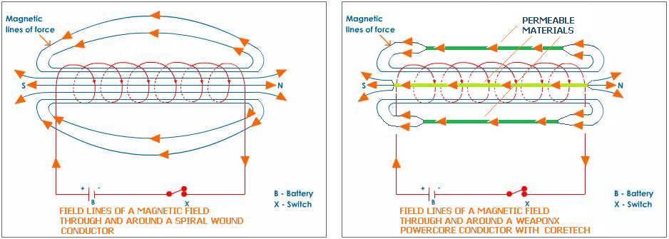
As a side benefit the magnetic lines of flux do not disturb electronic equipment around the wires because they do not travel outside the wire itself. All other wires produced have this magnetic field travelling outside the wire which can allow it to interfere with the electronics in the vehicle, including OEM wire.
Firstly, as seen in the dyno above reducing system resistance about 10000 ohms by removing the resistor in the spark plug nets a few hp with some respectable numbers at redline. Reducing system resistance 1000 ohms in the ignition wire may give you 1/10th that, or about .4hp across the band so what we needed to accomplish was energy recovery where it made the most sense to gain the highest power possible.
The real differences come into play with the types or materials used and our CORE technology.
To explain.
I already mentioned that the magnetic field is what is responsible for taming electrical interferences. This is because it is a source of energy. Current through any conductor will create a magnetic field and remember that wraps of wire (inductor) create a stronger field around a core / wire and want to keep current steady in the system. So, when the wire with these wraps (inductor) sees the spark energy dropping it wants to compensate by maintaining the spark. CORE tech is a technology we introduced that takes the magnetic field and enhances and re-harnesses it where most typical designs waste the energy.
In a typical wire these stray magnetic fields are called lines of flux. To understand more in the next paragraph it should be noted that magnetic fields are very similar to electricity in that they have preferred mediums to travel through.
For electricity we all know that copper is the best conductor and that stainless is a very poor electrical conductor. For magnetic fields there are materials that are said to be permeable which means that the magnetic lines of flux travel easier and more efficiently through that material without loosing energy. Much like copper is a good conductor for electricity we use a permeable ferrous and conductive material around our spiral core to more effectively allow the magnetic fields to maintain their strength and much like electricity conducts poorly through stainless steel magnetic lines of flux conduct poorly through the air. All styles, except our PowerCORE ignition wire, wastes this energy and it is lost from the wire, including zero ohm conductors.
We have also added this material to the core of the wire so that the magnetic lines of flux can travel easier and maintain their energy in the system. This helps maintain spark current and energy rather then waste it travelling through the air. Because of this technology we found that the returns by harnessing the magnetic field were greater then typical spiral wound designs.
As a side benefit the magnetic lines of flux do not disturb electronic equipment around the wires because they do not travel outside the wire itself. All other wires produced have this magnetic field travelling outside the wire which can allow it to interfere with the electronics in the vehicle, including OEM wire.
Last edited by WeaponX_Perf; 10-05-2011 at 09:11 AM.
10-05-2011, 09:17 AM
#11
FormerVendor
Thread Starter
Join Date: Jul 2008
Posts: 77
Likes: 0
Received 0 Likes
on
0 Posts
Retail is $109.99 for a pre-assembled set or $89.99 for an un-assembled set that includes about 12 feet of 8.8mm PowerCORE wire and all necessary boots and connectors. We have a promo going on for LS1TECH members, if your interested PM me for details.
We also sell the boots and wire separately if a custom application is required.
Boots
http://www.weaponxperformance.com/ca...c54559bbfa8b3b
Wires
http://www.weaponxperformance.com/ca...c54559bbfa8b3b
We also sell the boots and wire separately if a custom application is required.
Boots
http://www.weaponxperformance.com/ca...c54559bbfa8b3b
Wires
http://www.weaponxperformance.com/ca...c54559bbfa8b3b
10-05-2011, 11:25 AM
#13
FormerVendor
Thread Starter
Join Date: Jul 2008
Posts: 77
Likes: 0
Received 0 Likes
on
0 Posts
10-06-2011, 10:42 AM
#14
FormerVendor
Thread Starter
Join Date: Jul 2008
Posts: 77
Likes: 0
Received 0 Likes
on
0 Posts
Conductor choices
Typically copper seems to be the number one choice for ignition wires, however there are some manufacturers using nickel, carbon and others using stainless steel.
CARBON
Typically carbon is used as a standard suppression ignition cable and comes in resistances of about 1000-5000ohms per foot. Not ideal, but suppresses ignition noise and ignition energy.
COPPER
The largest choice is the copper conductor. Excellent electrical conductivity, however, copper tends to oxidise easily. Take a look at any penny and it's clear the luster is gone. Oxidisation creates an electrical barrier and reduces electrical conductivity over time which can result in high resistance connection points over time and degraded performance. Also, if not crimped just right easily breaks the spiral wound conductor as copper is a weak metal to work with. These issues is why, from wire to wire, there are usually inconsistencies, especially over time, with the copper spiral wound core ignition wire.
NICKEL
Nickel is another conductor choice typically found in 600 ohm spiral wound wires. It is not as conductive as the copper core wire but resists oxidisation much better and is much stronger and resistant to core breakage, especially at the crimp near the connectors where copper wire can break.
STAINLESS
Stainless steel also exhibits the same traits as nickel but the carbon composition and other metal alloys used in it's makeup reduce electrical conductivity even further.
WHY RESISTANCE (OHMS) IS NOT THE PURE MEASURE OF PERFORMANCE
To note
Electrical Conductivity of Metals (Higher = better)
Copper 100
Zinc 28.2
Nickel 12-16 (STAINLESS ALLOY)
Steel 3-15 (STAINLESS ALLOY)
Titanium 5 (STAINLESS ALLOY)
Vanadium 6.6 (STAINLESS ALLOY)
To properly detect the conductivity of a metal the above values are measured using eddy current instruments that induce currents in conductive materials. They are used to detect flaws, determine thickness, inspect welds, measure conductivity, and sort alloys. There are some inherent issues with the measurements of stainless but that is another story in itself as stainless is not really a ferro magnetic material. (there are issues to this contributing to interference as well). Using these methods we can distinctively see the superiority of copper and nickel as a conductor over stainless steel.
There are wires on the market that are 0 ohm, but use a stainless core. All things considered equally there would be no way to distinguish between a piece of copper wire measuring 0 ohms and a piece of stainless steel at 0 ohms when using an ohm meter but clearly the copper wire would be a superior conductor. The resistance check merely tells us the connection is there not how well it is conducting.
How does WeaponX stack up?
WeaponX uses multiple conductors, which will be explained in greater detail later, but the primary method of electrical conduction is the nickel plated spiral wound copper core. Although more expensive this type of conductor offers several advantages over other designs.
1) It conducts just as efficiently as a pure copper conductor
2) It resists oxidisation at the connectors just like the nickel based spiral wound wires
3) It has a tensile strength high enough that is does not break when bent or crimped.
I will show some more details and pictures next post.
 10-11-2011, 10:28 AM
#17
FormerVendor
Thread Starter
Join Date: Jul 2008
Posts: 77
Likes: 0
Received 0 Likes
on
0 Posts
OK the next segment will deal with some of the smaller more subtle nuances of the ignition wire.
For example, the connection.
We should all be aware of the issues contacts can have when electricity runs through them. Over time we develop green oxidation. We should all know the havoc it causes in an electrical connection such as poor conductivity and eventually failure. An easy example of this is the green / white oxidation that occurs on our battery connections which eventually causes the battery from conducting all together.
With a copper wire this issue is especially prevalent, any moisture only worsens the condition.
Our competitor wire deals with this in a unique way. I had someone draw up what we found in the sample we have here.
What they did was use a rubber coating over the spiral wound copper conductor. As you can see they left segments of the copper wound conductor open so that when crimped a connection these small points would connect to the terminal and allow electricity to flow to the connection point. While this works at sealing our moisture the trapped air in the connection point still causes oxidization, much like the battery terminal, so over time the connection points degrade, loose performance and eventually fail. On a second note, unlike a battery, if the wire fails due to oxidization it becomes very hard to remove meaning the wire may become useless and require replacement.
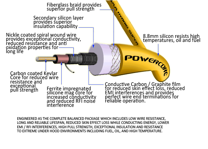
The PowerCORE 8.8mm wire uses a graphite skin over the spiral wound conductor. While it adds additional cost to the wire, this has several performance advantages which does several things.
First it lowers resistance of the wire, the connection point (since there is a higher cross section connection) and lowers the skin effect losses vs wire that comes in contact with a silicon/rubber insulator (more on this later). For the purpose of this post it creates a protective skin around the entire conductor. Since graphite is inert and does not react to the oxidization process it never decreases in performance over time. This Carbon-graphite is also inert to most chemical reagents so it survives where other materials fail meaning not only is it resistant to oxidization, but it is also resistant to chemicals, water and other in engine fluids meaning the connection will stay reliable for the life of the ignition wire.
For example, the connection.
We should all be aware of the issues contacts can have when electricity runs through them. Over time we develop green oxidation. We should all know the havoc it causes in an electrical connection such as poor conductivity and eventually failure. An easy example of this is the green / white oxidation that occurs on our battery connections which eventually causes the battery from conducting all together.
With a copper wire this issue is especially prevalent, any moisture only worsens the condition.
Our competitor wire deals with this in a unique way. I had someone draw up what we found in the sample we have here.
What they did was use a rubber coating over the spiral wound copper conductor. As you can see they left segments of the copper wound conductor open so that when crimped a connection these small points would connect to the terminal and allow electricity to flow to the connection point. While this works at sealing our moisture the trapped air in the connection point still causes oxidization, much like the battery terminal, so over time the connection points degrade, loose performance and eventually fail. On a second note, unlike a battery, if the wire fails due to oxidization it becomes very hard to remove meaning the wire may become useless and require replacement.
The PowerCORE 8.8mm wire uses a graphite skin over the spiral wound conductor. While it adds additional cost to the wire, this has several performance advantages which does several things.
First it lowers resistance of the wire, the connection point (since there is a higher cross section connection) and lowers the skin effect losses vs wire that comes in contact with a silicon/rubber insulator (more on this later). For the purpose of this post it creates a protective skin around the entire conductor. Since graphite is inert and does not react to the oxidization process it never decreases in performance over time. This Carbon-graphite is also inert to most chemical reagents so it survives where other materials fail meaning not only is it resistant to oxidization, but it is also resistant to chemicals, water and other in engine fluids meaning the connection will stay reliable for the life of the ignition wire.
 10-11-2011, 10:33 PM
#19

I have a question I'd like to ask. At what point does increasing spark energy not matter? Or if you keep increasing the spark energy, will the engine always create more power?
sorry, one more question: what are your thoughts on pulstar spark plugs? Those are the "million watt spark plug" ?
sorry, one more question: what are your thoughts on pulstar spark plugs? Those are the "million watt spark plug" ?
Last edited by 1 FMF; 10-11-2011 at 10:46 PM.
10-13-2011, 02:57 PM
#20
FormerVendor
Thread Starter
Join Date: Jul 2008
Posts: 77
Likes: 0
Received 0 Likes
on
0 Posts
I have a question I'd like to ask. At what point does increasing spark energy not matter? Or if you keep increasing the spark energy, will the engine always create more power?
sorry, one more question: what are your thoughts on pulstar spark plugs? Those are the "million watt spark plug" ?
sorry, one more question: what are your thoughts on pulstar spark plugs? Those are the "million watt spark plug" ?
Typically the stock ignition system is great and is designed for stock power levels but when you start to increase power levels above the OEM design specifications increasing spark energy will typically yield additional power, however, you are right, there is a point of diminishing returns.
If I had the same input energy into the ignition coils, which creates the same load on the alternator, and increase the efficiency of the spark event you usually will see improvements. We must keep in mind that the energy into a spark event can only do so much work. If we increase the efficiency, we increase the energy in the spark event for free, ie better wire, coils, plugs that spark can do more potential work in the combustion chamber the better the returns. The problem is gaining the efficiency in these components, we can only go so far with it due to interference and limitations on hardware.
When increasing input energy into a stock ignition / engine, with the same efficiency as the OEM setup, we may be at the ideal point so the only thing we accomplish there is wasted spark and not enough gain from engine HP to see any real world returns since we are also taxing the alternator which takes up HP. Now your only wasting energy.
This of course will vary. We have our ignition coils on a 1200rwhp vehicle, before the ignition coils the engine made 1000rwhp BUT this is in a case where the OEM ignition coils were insufficient to handle the demands being made on them. On a bone stock engine we typically see anywhere from 2-10hp depending on engine. Typically the gains are progressive. The more the demands on the ignition, the higher the hp your making, the more a better ignition system is typically required and the higher the returns from increased spark energy, but again you can hit that wall where more won't equal better. Typically OEM ignition components are made for OEM power levels. That is usually the limiting factor, however, making a more efficient spark will almost always net a power return.
Last edited by WeaponX_Perf; 10-13-2011 at 03:03 PM.