

LS3 Fuse Box Hook-Up
 08-15-2011, 10:14 AM
#1
Teching In
Thread Starter

Join Date: Apr 2010
Posts: 31
Likes: 0
Received 0 Likes
on
0 Posts
I'm trying to take some of the wiring for the LS3/T56 Install. The instructions that came with the GMPP harness/fuse box are meager at best, so I'm looking for a little help with integrating this with my Painless harness.
As of now (It is stuffed in a corner and I'm really not sure at this point if I'm going to keep it there since it may get wet
http://www.flickr.com/photos/modernm...in/photostream ), it looks like there are only two main wires coming out:
Grey: fuel pump
Blue: fan
However, I saw from another thread where someone was putting in an LS3 that those two main studs have wires connected to them as well (roughly 12 gauge). I assume at least one is a power wire. Can anyone offer some direction in this department? How many connections should I plan to make to get it to mate to my Painless harness? I have almost no idea how to wire this up due to the lack of instructions that came with it. I have already mostly installed the Painless harness throughout the rest of the car, so I assume minimal connections need to be made.
I'd really like my fans to be powered per the attached:
http://farm7.static.flickr.com/6074/...05032577_o.png
(two electric fans) but the LS3 fuse box only has one relay and one wire. I have other external relays ready to go under my dash, but I have read that it is better to have the ECU control the fans.
Here is some info on my ECU if that helps...
GM Racing
GM# 19258268
Gr. 3.670
GM Performance Parts LS376
Also, the diagram on my fuse box cover is faded after being left out in the sun for a day, so if anyone can provide a screenshot of theirs, that'd be great. Or...maybe I can just order another cap?
 08-16-2011, 05:25 AM
#2
Staging Lane

Join Date: Feb 2010
Location: UK Leeds
Posts: 61
Likes: 0
Received 0 Likes
on
0 Posts

I dont know what a 'Painless' harness is...but the two studs are for in/out 12v power from the battery. I have mine going on to the car relay box from there. In addition to the two wires there should be a connector called 'bulkhead connector'. Use that to hook up all other signals (tacho, mil etc). I have an installation guide coving that. Can e mail it if you need it...
Mark
Mark
08-16-2011, 07:47 AM
#3
Teching In
Thread Starter
Join Date: Apr 2010
Posts: 31
Likes: 0
Received 0 Likes
on
0 Posts
Thanks for the response. "Painless" is the brand of my internal car wiring harness (they sell a lot of harnesses for cars).
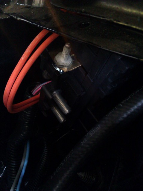
After looking a little more closely, these are the primary connections I have (separate from the connections that go to sensors:
Grey (fuel pump) - I can wire this one up
Blue (fan) - I can probably figure this one out
Bulkhead connector - All the misc signals - I can probably figure this one out as well
Threaded terminal A
Threaded terminal B
Extra threaded terminal that appears to be some sort of bus bar
(The instructions state that there is supposed to be a pink wire for the 12V connection, but there is no pink wire coming out of the fuse box)
In bold is what I don't know how to hook up. See attached photo below. At the top you'll see the extra (oriented 90 degrees from the other ones) threaded terminal. Is this a ground or a powered source?
Something else to note: on the back side of the two terminals that are oriented together is the text "RED." So, is one of these a power and one a ground? Concerning the power wires, should be be a switched wire or a constant power from the battery?

Trending Topics
10-17-2023, 10:01 PM
#8
TECH Senior Member


