
Need someone to verify brake switch wiring please
 12-16-2011, 12:58 PM
#1
Teching In
Thread Starter
Join Date: Mar 2009
Location: Utah
Posts: 44
Likes: 0
Received 0 Likes
on
0 Posts
I am almost done swapping and wiring a LS1/4L60 into my 63 chevy c10 truck and have a quick question. I have been reading here on LS1 tech and even though this was recommended I didn't read anywhere that mentioned someone actually tried this to see if it actually works or not.. Has anyone actually wired their vehicle like this and have everything work like it should? Any recommendations or other ideas will be greatly appreciated. This is the last thing I need to wire up on the harness. Thank you.
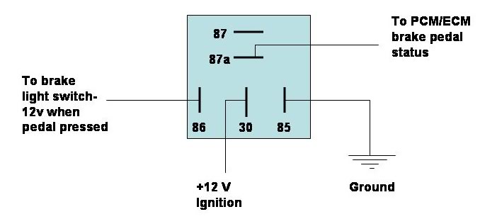
Pros and cons to this? Will this retain my brake lights and use my existing 63 chevy brake switch and still give the ECM what it needs? I'm sure it will be annoying to hear the relay click every time I press the pedal but if it works then so be it.
Pros and cons to this? Will this retain my brake lights and use my existing 63 chevy brake switch and still give the ECM what it needs? I'm sure it will be annoying to hear the relay click every time I press the pedal but if it works then so be it.

 12-16-2011, 01:06 PM
#3
Teching In
Thread Starter
Join Date: Mar 2009
Location: Utah
Posts: 44
Likes: 0
Received 0 Likes
on
0 Posts
 12-16-2011, 01:25 PM
#4
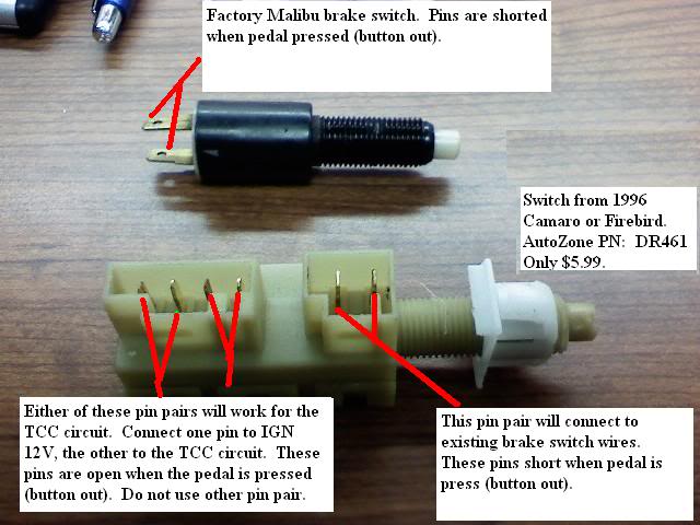
Yes, the picture of the 2 position brake switch makes much more sense.
Jon
PSI
Jon
PSI
__________________

Your Source for LSX Conversion Parts!
www.psiconversion.com
Ebay Store
Facebook/psiconversion
Instagram/psiconversion
'Dont Let EFI Pass You By!'
Your Source for LSX Conversion Parts!
www.psiconversion.com
Ebay Store
Facebook/psiconversion
Instagram/psiconversion
'Dont Let EFI Pass You By!'
 12-16-2011, 03:34 PM
#6
Teching In
Thread Starter
Join Date: Mar 2009
Location: Utah
Posts: 44
Likes: 0
Received 0 Likes
on
0 Posts

 12-16-2011, 03:48 PM
#8
Teching In
Thread Starter
Join Date: Mar 2009
Location: Utah
Posts: 44
Likes: 0
Received 0 Likes
on
0 Posts
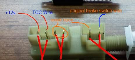
great, that's what i'll do then. I just wasn't sure if I needed to put the TCC wire on the set of pins next to it or if it went right next to the +12v pin.. That's what I wanted to verify. So the way my picture looks is correct? I leave the 3 pins open without anything on them just as the pic shows? Thanks guys, Saved me a big headache.. I hate guess work when it comes to wiring so I appreciate the answers and advice.
nathan
nathan
12-17-2011, 07:05 AM
#9
great, that's what i'll do then. I just wasn't sure if I needed to put the TCC wire on the set of pins next to it or if it went right next to the +12v pin.. That's what I wanted to verify. So the way my picture looks is correct? I leave the 3 pins open without anything on them just as the pic shows? Thanks guys, Saved me a big headache.. I hate guess work when it comes to wiring so I appreciate the answers and advice.
nathan
nathan
12-17-2011, 04:42 PM
#10

OK, to add to this...
I am doing a swap in my mustang and I dont have the option of using that switch shown. Would the OP's orginal diagram with the relay work for my application?
I am doing a swap in my mustang and I dont have the option of using that switch shown. Would the OP's orginal diagram with the relay work for my application?
12-17-2011, 06:37 PM
#12
Teching In
Thread Starter
Join Date: Mar 2009
Location: Utah
Posts: 44
Likes: 0
Received 0 Likes
on
0 Posts
I wire it how my modified diagram shows it right? I still haven't wired this, I hope to do it this weekend if my back will ever quit hurting.
Last edited by nesluopetan; 12-18-2011 at 05:13 PM.
12-17-2011, 06:43 PM
#13
Teching In
Thread Starter
Join Date: Mar 2009
Location: Utah
Posts: 44
Likes: 0
Received 0 Likes
on
0 Posts
12-17-2011, 09:17 PM
#14
Launching!
iTrader: (1)
Join Date: Apr 2011
Location: Adamsville Tennessee
Posts: 231
Likes: 0
Received 0 Likes
on
0 Posts
Just splice into your brake light hot wire and send it to 87a on relay. Think of it as a T off the original brake light wire. All you want is the power from the brake light when pushed to trigger the relay and open 87a and close 87.
12-17-2011, 09:37 PM
#15
We wire many of them in my shop with a relay as pictured in the first post. No reason not to do it that way and in the case of many swaps it's the best way due to either a mechanical brake pedal switch or hydraulic style switch, which are both common on many older cars/ street rods/ etc.
12-18-2011, 01:19 PM
#17
I had questions about this as well. On my harness i have a pink and a purple marked "tcc brake switch" this is for am 87 chevy short bed truck. Which wire goes where?I ll probably pick up the 96 camaro brake switch. i dont have it hooked up at this time but the trans seems to shift fine.
12-18-2011, 01:24 PM
#18
^^ I would assume on your harness the pink supplies the keyed power to the brake switch and the purple is the wire the signal returns on to the PCM. Did your harness not come with instructions or offer tech support, or is it a stock harness that someone modified?
12-18-2011, 01:39 PM
#19
it has a pdf file that came by email that was a good help but it just shows how to run it to a relay. i wanted to just hook it up to brake switch like most people are doing
12-18-2011, 01:58 PM
#20
Any of the dual function style brake switches like the ones pictured should hook up simply. Most GM vehicles from the mid 80's on up already have that style switch installed.
If you have a multi-meter you can set it to the ohm setting and touch both terminals near each other. Once set will show a connection when the brake pedal is pressed. This set would be used for the brake lights. The other set of terminals should show a connection when the pedal is NOT pressed and will lose the connection when the pedal is pressed. This would be the proper terminals to use for the lockup converter connection.
The end goal is to have 12 volt keyed power applied to the PCMs wire (purple in this and most cases) when the brakes are NOT applied, and then to lose the 12 volt keyed power when the brake is pressed. This will kill power to the converter and unlock it when the brakes are pressed.
A normal, single function brake switch, generally with one pair of terminals will connect the two terminals together within the switch once its activated by the pedal to complete the circuit for the brake lights to come on, this style would be where you can wire in the relay if you do not desire to replace the switch with the multi function style.