

My Pro-Touring Project - 1969 Camaro LSX427 TT
 03-29-2016, 01:48 PM
#141

Yea I didn't enjoy seeing it as it happened, but it's in the past now!
Working on the wiring. Installed the AC this past weekend. Ordered the remaining stuff for my dash panel so I can make that work with the racepak how i want and move on to get it painted and installed.
Brakes are also 100% complete, function test this weekend, and clutch should be finished soon (need a -3 GM clutch line...).
Driveline/mechanical/hotside are 100% complete. Need to do wiring, then install the front end and work on finishing the cold side and button it all up. Hoping it starts sometime this summer.
 03-29-2016, 02:14 PM
#142

What base pressure will you running the dual CTS-V pumps at? I ask just because the LPH drops off a good bit from 60 to 65 psi and again 65 to 70. I'm guessing you'll be running 93 octane and not E85. So roughly 400lph with base pressure of 50psi and 20lbs boost. Sorry I'm kind of thinking out loud here as well as asking.
03-29-2016, 04:14 PM
#143
i got a fuel pump controller from a company called vaporworx which has some pretty extensive testing on fuel pumps and GM specifically.
From his results:
13.5v/60psi results in 482lbs/hr (from each CTS-V unit)
You can run them up to 65psi but start to see loss of flow as an internal poppet bypass opens at around there and it starts bleeding back into the tank (internally regulated).
You can use a BAP but I'm not currently planning that as I'll have roughly 950lbs/hr available at 60psi. My concern is not being able to increase the pressure high enough with boost to give a good delta across the injector (60-65psi w/ 18-20psi boost = 40-47psi). So i went big injector so low pressure diff flow could accommodate. I will run E85, but suspect pumps will only accommodate ~1000-1100rwhp. Down the road, I will swap out one of those pumps with a Fore hat with 3x485s and run that in PWM.
Looking back i'd have done a slightly different system but it is what it is at this point. I can change it later if it doesn't fulfill my power goals.
03-31-2016, 12:40 AM
#144

i got a fuel pump controller from a company called vaporworx which has some pretty extensive testing on fuel pumps and GM specifically.
From his results:
13.5v/60psi results in 482lbs/hr (from each CTS-V unit)
You can run them up to 65psi but start to see loss of flow as an internal poppet bypass opens at around there and it starts bleeding back into the tank (internally regulated).
You can use a BAP but I'm not currently planning that as I'll have roughly 950lbs/hr available at 60psi. My concern is not being able to increase the pressure high enough with boost to give a good delta across the injector (60-65psi w/ 18-20psi boost = 40-47psi). So i went big injector so low pressure diff flow could accommodate. I will run E85, but suspect pumps will only accommodate ~1000-1100rwhp. Down the road, I will swap out one of those pumps with a Fore hat with 3x485s and run that in PWM.
Looking back i'd have done a slightly different system but it is what it is at this point. I can change it later if it doesn't fulfill my power goals.
From his results:
13.5v/60psi results in 482lbs/hr (from each CTS-V unit)
You can run them up to 65psi but start to see loss of flow as an internal poppet bypass opens at around there and it starts bleeding back into the tank (internally regulated).
You can use a BAP but I'm not currently planning that as I'll have roughly 950lbs/hr available at 60psi. My concern is not being able to increase the pressure high enough with boost to give a good delta across the injector (60-65psi w/ 18-20psi boost = 40-47psi). So i went big injector so low pressure diff flow could accommodate. I will run E85, but suspect pumps will only accommodate ~1000-1100rwhp. Down the road, I will swap out one of those pumps with a Fore hat with 3x485s and run that in PWM.
Looking back i'd have done a slightly different system but it is what it is at this point. I can change it later if it doesn't fulfill my power goals.
If twin CTS-V modules are used the 65psi max still applies. If twin 450's are in the secondary a higher pressure can be used. In this case (EDIT) a check valve will need to be added after the outlet of the CTS- module but before the Y-block. In this case only the twin 450's will send fuel to the engine.
Last edited by CarlC; 04-05-2016 at 02:14 AM.
03-31-2016, 07:17 AM
#145
Yep. We've talked about this :-). Didn't know you were on here Carl!
In hind sight I would have likely done one pump with your controller. I may do two pump setup in the future and know to keep ctsv I have to run a check valve and make sure 2nd pump can support all the fuel needs.
For now I bet these two ctsv will be plenty. It's sad that I already have the next revision of this setup planned before the car even runs...
03-31-2016, 11:17 AM
#146

CarlC,
Thanks for chiming in here.
Thanks for chiming in here.

 04-18-2016, 04:42 AM
#151
More work this weekend.
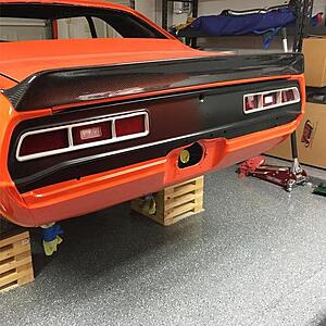
Took a break from the metal work and decided to modify the tail light buckets for the LED panels. Overall not too bad but the brackets that are included fit like ****.


Then decided to put the glovebox in the car and check fit and begin wiring (you can see rear light wiring already run to the trunk in previous picture.


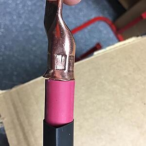
Also ran the pain power cable. 2/0 welding cable. Pretty intense stuff and a beastly crimper needed to attach the lugs.


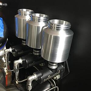
Picked up a product called Shine Seal from the original founder of Zoopseal in an effort to seal the raw aluminum I have in the engine bay. I cleaned all these panels and lightly brushed with a 3m pad.

Did the reservoirs also.
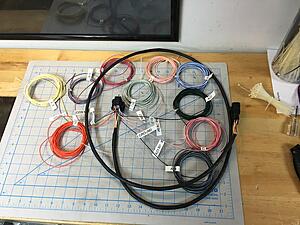
Lastly I started working on the Holley wiring and making good progress for a short amount of time. I hope to have this harness completed and modified for my setup by this weekend. Hope I can find the time to hit the garage hard this week.


Test fitting intake and verifying lengths of harness.

William
Took a break from the metal work and decided to modify the tail light buckets for the LED panels. Overall not too bad but the brackets that are included fit like ****.


Then decided to put the glovebox in the car and check fit and begin wiring (you can see rear light wiring already run to the trunk in previous picture.


Also ran the pain power cable. 2/0 welding cable. Pretty intense stuff and a beastly crimper needed to attach the lugs.


Picked up a product called Shine Seal from the original founder of Zoopseal in an effort to seal the raw aluminum I have in the engine bay. I cleaned all these panels and lightly brushed with a 3m pad.


Did the reservoirs also.

Lastly I started working on the Holley wiring and making good progress for a short amount of time. I hope to have this harness completed and modified for my setup by this weekend. Hope I can find the time to hit the garage hard this week.


Test fitting intake and verifying lengths of harness.

William

 04-29-2016, 05:59 AM
#156
Thanks. I'm working on how to keep it clean as possible. Basically every hose you see with be fragola braided and black. The radiator hoses are hard piped and rubber couplers. All wiring will be loomed in black techflex or the black look that Holley uses.
Should look good!
Should look good!
05-02-2016, 09:40 AM
#158
Got back after it this past week/weekend and got a few things accomplished (mostly yesterday).
Tail lights Installed:

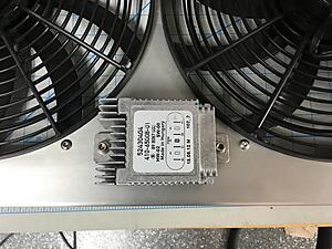
I have a C6 PWM fan controller, and wanted to find a good place for it that was out of the way. Core support went back on to see if the spot i wanted will work.

Lots of space!


Made me nervous drilling and putting nutserts in the beautiful shroud, but it needed to be done!


Next up was finishing the turbo drains and hooking up the power steering lines.
Hard to tell but the turbo drains are in place here, -10 90deg to -10 PTFE to the pan, and a 120deg fitting into the pan. That area is relatively flat but does have a slight uphil right at the end (passenger side mostly, to clear the starter).

Power steering lines were a PITA. To get them tight on the rack, I had to pull the rack hardlines to have access. They're done and hardlines are back in place.


Decided to tackle one of the jobs I was least looking forward to...Drilling the firewall for the ac bulkhead. I had to pull the AC back out and the glove box to have access to put these in place.


Since the AC was out, I mounted my bulkhead for the power cable from the top. Kept me from having to remove passenger downpipe to have access to drill it.


After getting those holes cut, I decided I'd take my chances and drill out the hole in the firewall for the wire pass through. I wanted to mount it a little lower, but lower and it would have interference inside, towards middle and it would hit map sensor, and other side had fuel pressure sensor and some difficult structure to work around.


No turning back now.


Pinned all the additional wires in the input/output harnesses for the holley and labeled them all.

Now i'll strip the rest of the loom off the original harness, lay these together and put it through the fiewall and start plugging it in so I can make the engine bay side all perfect length.
That's where she sits now.
William
Tail lights Installed:


I have a C6 PWM fan controller, and wanted to find a good place for it that was out of the way. Core support went back on to see if the spot i wanted will work.

Lots of space!


Made me nervous drilling and putting nutserts in the beautiful shroud, but it needed to be done!


Next up was finishing the turbo drains and hooking up the power steering lines.
Hard to tell but the turbo drains are in place here, -10 90deg to -10 PTFE to the pan, and a 120deg fitting into the pan. That area is relatively flat but does have a slight uphil right at the end (passenger side mostly, to clear the starter).

Power steering lines were a PITA. To get them tight on the rack, I had to pull the rack hardlines to have access. They're done and hardlines are back in place.


Decided to tackle one of the jobs I was least looking forward to...Drilling the firewall for the ac bulkhead. I had to pull the AC back out and the glove box to have access to put these in place.

Since the AC was out, I mounted my bulkhead for the power cable from the top. Kept me from having to remove passenger downpipe to have access to drill it.


After getting those holes cut, I decided I'd take my chances and drill out the hole in the firewall for the wire pass through. I wanted to mount it a little lower, but lower and it would have interference inside, towards middle and it would hit map sensor, and other side had fuel pressure sensor and some difficult structure to work around.


No turning back now.


Pinned all the additional wires in the input/output harnesses for the holley and labeled them all.


Now i'll strip the rest of the loom off the original harness, lay these together and put it through the fiewall and start plugging it in so I can make the engine bay side all perfect length.
That's where she sits now.
William
05-02-2016, 11:28 AM
#159
Badass!!!!!!! Nuf said
05-03-2016, 12:54 PM
#160
Thanks man. Taking a long time, but starting to take shape.
Baby steps, small weekday projects.
Trying to make time to get into the garage and knock out small items during the week since I cant dedicate significant time to the garage (usually 2-3hours MAX during the week days).
I got out there yesterday to sort the steam vent concern. The kit I had I made look decent I think.


Plenty of room at the rear of the engine. Sits well under the map sensor/etc.

Front is a little closer, specifically the fitting by the fuel line crossover.

There is a gap, but it's paper thin.

The line off the tee fitting on the front will go back to the radiator here

I ordered the 1/4" NPT to -4 AN adapter so I can complete that line and have it follow the radiator hose route. Should be very clean looking once completed.
William