
Let's talk using a Stock Harness. Who has all done it. Any issues or Tips?
 04-09-2014, 09:04 PM
#1
Teching In
Thread Starter

Join Date: May 2002
Location: Orland
Posts: 42
Likes: 0
Received 0 Likes
on
0 Posts

Title says it ..... Doing a 5.3 swap into a Rat Rod and have a Fbody Harness and the Truck Harness, should I just use one of those? Don't care about the look.
 04-09-2014, 09:23 PM
#2

It really depends your comfort level with reworking the harness or willingness to pay for a harness that you can just install.
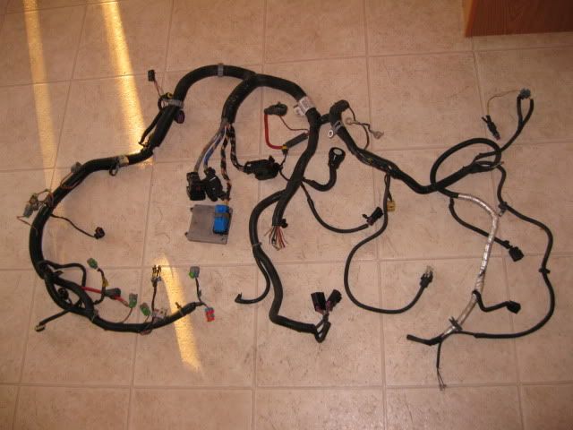
I did it the hard way, but I had a very specific look I wanted from the swap/harness... I started with this:
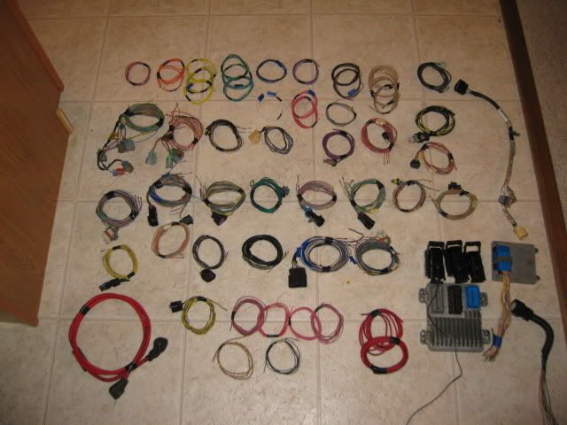
Did this to it:
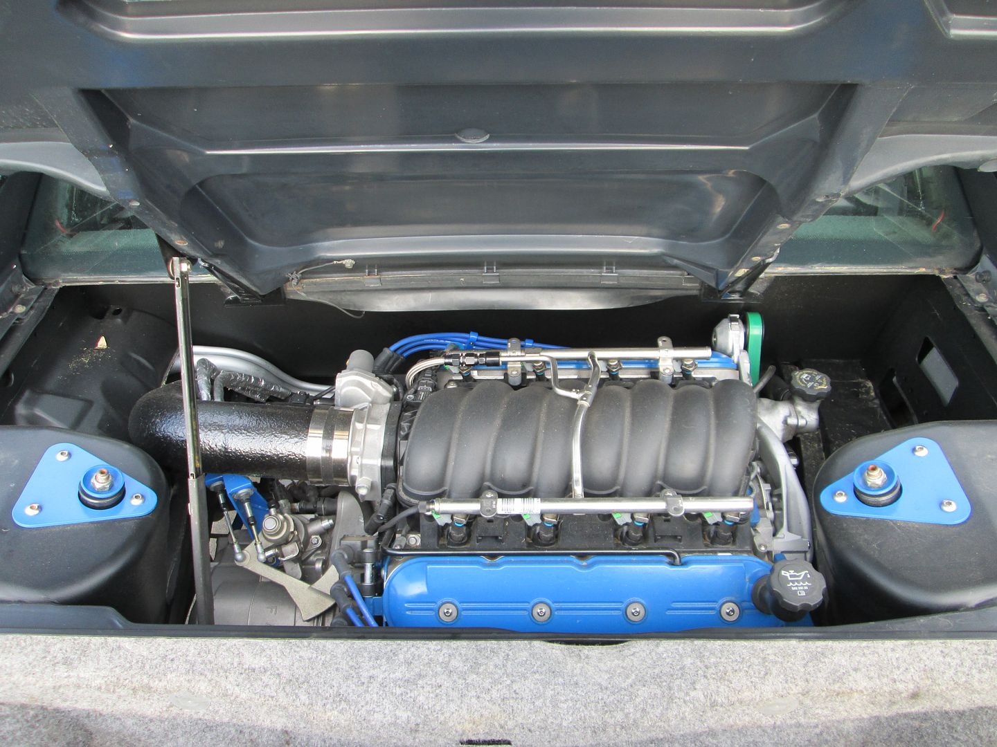
Finished swap:
I did it the hard way, but I had a very specific look I wanted from the swap/harness... I started with this:
Did this to it:
Finished swap:
04-09-2014, 09:27 PM
#3
I hooked it up, and put tape on the connectors labeling them. Layed the harness on the ground and removed the conduit. Removed all wires I didn't need. This is the time to decide where you want your harness to run, so you can put new conduit on to route your connectors nice and cleanly on the engine.
04-09-2014, 10:01 PM
#5
It basically comes down to PCM location I believe. Trucks are mounted in the left front of the engine bay, while the FBody are inside or under the wheel liner like Corvettes.
04-09-2014, 11:01 PM
#6
On The Tree

Join Date: Oct 2012
Location: ARIZONAA
Posts: 185
Likes: 0
Received 0 Likes
on
0 Posts
I did mine for my swap and I hated every second of sorting through the spaghetti i was given, even now that my swap has been running for 7 months and the harness works its doesn't look how i wish it would've and i done have and extra harness that I could send out or redo the way i want to.
04-10-2014, 08:00 AM
#7

My advice is to run it how you want 1 sensor at a time. That will give you the best results. I used lt1swap.com and removed all the wires from the computer connector side after labeling them of course. It's really not that hard it just takes a really long time and multiple goes at it. In the end I ended up ordering new computer pins and wire and just clipped the sensor connectors with about 3-4" of wire and soldered them on that way I could run the length and route that I wanted to run.
Trending Topics
 04-10-2014, 09:21 AM
#9
I did mine from a fbody harness. If you don't care about stripping the unused wires it can be super easy. Just locate the 3 body harness plugs and follow the wiring tutorials in the sticky.
Basically: switched power to pink, constant battery power to orange, ground to black, purple wire to starter. Fuse and relay them accordingly for their functions and the car will run.
Aside from that it's just a matter of finding the tach signal wire for gauges and the one for the OBDII port.
I unpinned the unused wires from the PCM connector but left them in the harness.
04-10-2014, 12:07 PM
#10
Yes, heat shrink tube on the top side and most shorter legs of the harness. I like heat shrink because it makes the harness as thin as possible while still providing for some abrasion resistance. I did use normal split loom where it goes over the bellhousing, to the ecm and into the chassis. The split loom made it easy for the coil wires to join the main harness. Here is where I started on the injector harness:
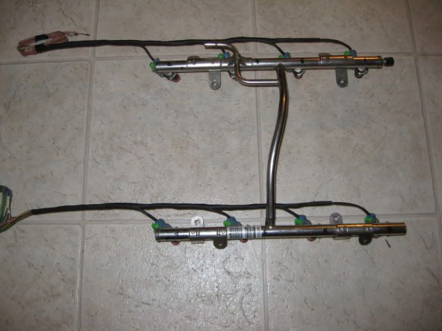
Then I wire tied them to the backside of each fuel rail to hide the injector connector and harness as much as possible.

 04-10-2014, 05:22 PM
#13
Launching!
iTrader: (1)
Join Date: Mar 2006
Location: tulsa oklahoma
Posts: 277
Likes: 0
Received 0 Likes
on
0 Posts
I redid mine with an Fbody harness. Just make sure its not a 1998, those are different.
It is not a fun thing to do if your not a big electrical guy, but you can do it if you take your time and label everything.
A couple things that I had to learn the hard way:
1. If your going to splice the wires when shortening/lengthening then stagger your splices. If a sensor has 4 wires and you splice them all at the same location then you have a bulky section that doesn't look as good and if you have any sharp spots in the splice then they can poke through your heatshrink and short the wires.
Took me a while to figure out why my engine wouldn't run anymore, crank sensor wires shorted because of the above situation.
2. Use Marine grade heatshrink. I used the normal heatshrink but the marine stuff is adhesive lined so when it shrinks it also melts the adhesive so it is water tight.
If I was to do it again I would just get tiny bare crimp connectors instead of soldering.
Good luck!
BTW fieroguru that looks really good!
04-10-2014, 09:34 PM
#16
Teching In
Thread Starter
Join Date: May 2002
Location: Orland
Posts: 42
Likes: 0
Received 0 Likes
on
0 Posts
I did mine from a fbody harness. If you don't care about stripping the unused wires it can be super easy. Just locate the 3 body harness plugs and follow the wiring tutorials in the sticky.
Basically: switched power to pink, constant battery power to orange, ground to black, purple wire to starter. Fuse and relay them accordingly for their functions and the car will run.
Aside from that it's just a matter of finding the tach signal wire for gauges and the one for the OBDII port.
I unpinned the unused wires from the PCM connector but left them in the harness.
Basically: switched power to pink, constant battery power to orange, ground to black, purple wire to starter. Fuse and relay them accordingly for their functions and the car will run.
Aside from that it's just a matter of finding the tach signal wire for gauges and the one for the OBDII port.
I unpinned the unused wires from the PCM connector but left them in the harness.
04-10-2014, 09:48 PM
#17
On The Tree

Join Date: Feb 2014
Posts: 102
Likes: 0
Received 0 Likes
on
0 Posts
Doing your own harness will teach you a lot about the engine and how it operates if you do not have experience with fuel injection.
I think the hardest part for me was adding the fuse box.
I think the hardest part for me was adding the fuse box.
04-11-2014, 11:11 AM
#19
Can't believe no one has mentioned this..... http://lt1swap.com/2000harness.htm
This should get you going, as long as you have some kind of understanding of how electrical systems work, and can use a soldering iron.
This should get you going, as long as you have some kind of understanding of how electrical systems work, and can use a soldering iron.