
My catch can routing ok?
 10-08-2009, 06:21 PM
#281

I use these on my 04 Cobra. The work very well.
http://www.aircraftspruce.com/catalo...checkvalve.php
http://www.aircraftspruce.com/catalo...checkvalve.php
This is something I've been researching and testing for a long time. One would think these are easy to come by, but not so. A PCV valve can be used but they only limit flow in one direction under extreme conditions and they leak..
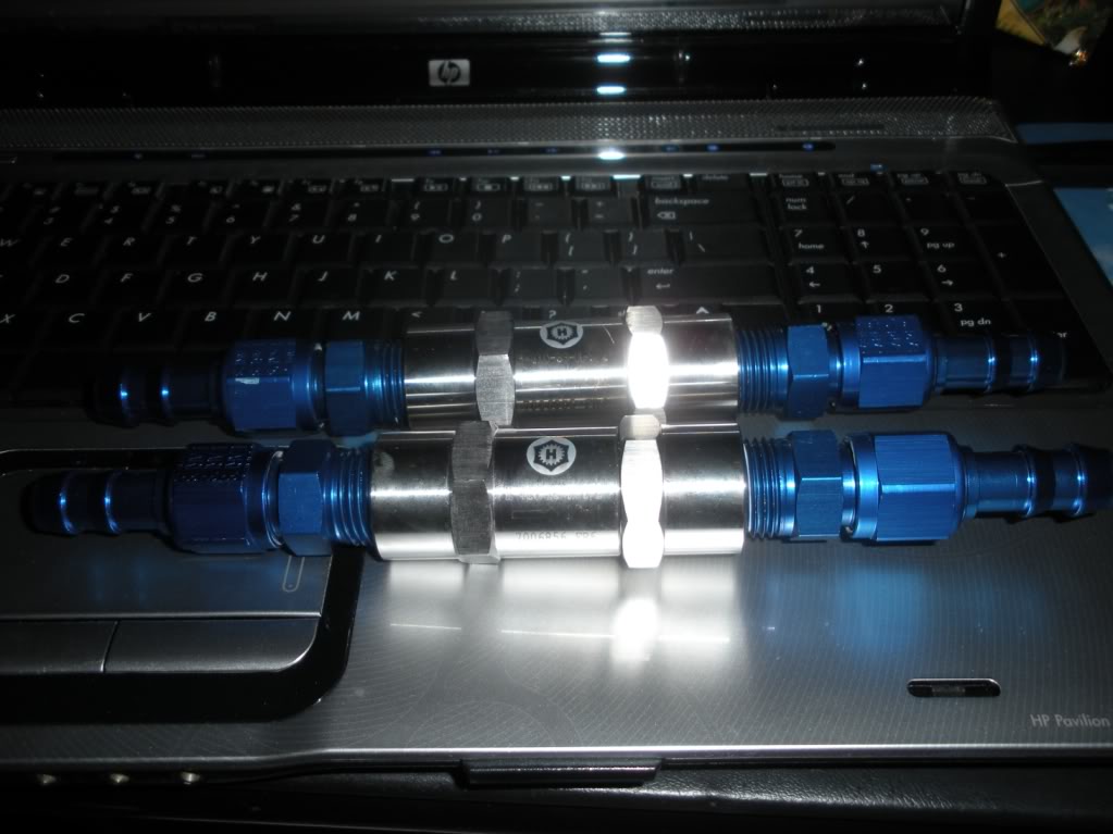
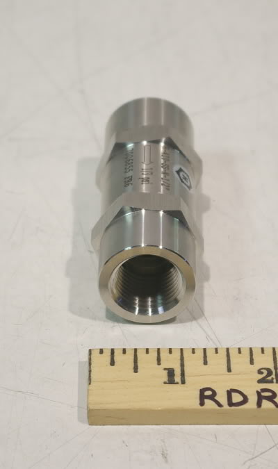
Currently, the only true one-way valve that I know works, does not limit flow, is compact for easy installation, and has a low cracking pressure (important) is the Krank Vent by ET Performance. They are expensive, but they work.
I have another much lower cost, equal performance (on paper), and very promising candidate but they are on a 7 week back order. Once I verify its functionality I'll be ready to recommend. I don't want anyone to waste their time and money until I know it works.
HTH,
 10-10-2009, 10:59 AM
#282

I use these on my 04 Cobra. The work very well.
http://www.aircraftspruce.com/catalo...checkvalve.php
http://www.aircraftspruce.com/catalo...checkvalve.php


 10-15-2009, 01:37 PM
#286
TECH Enthusiast
iTrader: (6)

Join Date: Aug 2002
Location: Readsboro, VT
Posts: 529
Likes: 0
Received 0 Likes
on
0 Posts

Outstanding thread. I'm just now getting started with an LQ9 build up for my IROC, and this thread has helped explain a lot. I learned the hard way about PVC usage with the motor that's currently in the car (350 TPI). With only a few thousand miles on the car, I had oil leaking out of almost every single engine gasket because I had the crankcase completely closed up.
However, after reading this thread, I'm confused on a few things that are probably very simple, but I just somehow missed their explanations.
I'm confused by this clean side/dirty side thing. Why is one side cleaner than the other? What's the difference?
Taking the simplest N/A configuration, I see that the driver side (clean side?) has a line directly from the throttle body to the valve cover. The passenger side has a line from the valve cover, through the PCV valve back to the TB, and if we add a catch can, we insert it in-line with that path. Similar configuration to the PCV I run on my SBC, except that my PCV valve is on the driver side. I always thought of this as a circular path for the air to flow... it flows from the intake, to one valve cover, through the motor, and back to the intake through the PCV valve... but really there's vacuum pulling on both lines... the "feed" going to one valve cover, and also on the PCV side. If that's the case, aren't both lines pulling crankcase gasses out? Where does it get it's "Feed" if both lines are pulling vacuum?
I hope these questions aren't too basic... I thought I understood the whole concept of PCV, but the more I look at these diagrams, the more I realize that there are some real holes in my understanding.
10-27-2009, 01:35 PM
#287

Great thread!!!
I built a stout little motor from an 05 gto block and won my class at the kit car nationals a few weeks ago but realized the two breathers on my valve covers let out quite a bit of fummage and oil. I will be adding the saikou dual cans but seeing as I pieced the motor together from a block and have none of the origanal pcv stuff I'm left with a few questions but think I figured it out from this thread.
My motor is carbed and I'm assuming the clean line would then go to the carb spacer?
So back of valve covers tied together..
pass front to top of can..
outlet to carb spacer..
valley plate to top of the other can...
outlet to spacer plate....
and leave my two breathers on the valve covers.
For just a n/a application( like the gm 376/515 crate motor) do i need to add a pcv inline?
I'm sorry to be so dense but it took me a week to get thru this whole thread and understand everything that applied to me.
thanx again,
chris.
10-27-2009, 05:20 PM
#288
Taking the simplest N/A configuration, I see that the driver side (clean side?) has a line directly from the throttle body to the valve cover. The passenger side has a line from the valve cover, through the PCV valve back to the TB, and if we add a catch can, we insert it in-line with that path. Similar configuration to the PCV I run on my SBC, except that my PCV valve is on the driver side. I always thought of this as a circular path for the air to flow... it flows from the intake, to one valve cover, through the motor, and back to the intake through the PCV valve... but really there's vacuum pulling on both lines... the "feed" going to one valve cover, and also on the PCV side. If that's the case, aren't both lines pulling crankcase gasses out? Where does it get it's "Feed" if both lines are pulling vacuum?
I hope these questions aren't too basic... I thought I understood the whole concept of PCV, but the more I look at these diagrams, the more I realize that there are some real holes in my understanding.
I hope these questions aren't too basic... I thought I understood the whole concept of PCV, but the more I look at these diagrams, the more I realize that there are some real holes in my understanding.
The dirty side connects from the valley cover or opposing valve cover to the intake manifold plenum chamber (engine vacuum).
Blowby can flow out the clean side when dirty side flow is insufficient to overcome blowby production.
HTH,
10-27-2009, 05:30 PM
#289
Great thread!!!
I built a stout little motor from an 05 gto block and won my class at the kit car nationals a few weeks ago but realized the two breathers on my valve covers let out quite a bit of fummage and oil. I will be adding the saikou dual cans but seeing as I pieced the motor together from a block and have none of the origanal pcv stuff I'm left with a few questions but think I figured it out from this thread.
My motor is carbed and I'm assuming the clean line would then go to the carb spacer?
So back of valve covers tied together..
pass front to top of can..
outlet to carb spacer..
valley plate to top of the other can...
outlet to spacer plate....
and leave my two breathers on the valve covers.
For just a n/a application( like the gm 376/515 crate motor) do i need to add a pcv inline?
I'm sorry to be so dense but it took me a week to get thru this whole thread and understand everything that applied to me.
thanx again,
chris.
I built a stout little motor from an 05 gto block and won my class at the kit car nationals a few weeks ago but realized the two breathers on my valve covers let out quite a bit of fummage and oil. I will be adding the saikou dual cans but seeing as I pieced the motor together from a block and have none of the origanal pcv stuff I'm left with a few questions but think I figured it out from this thread.
My motor is carbed and I'm assuming the clean line would then go to the carb spacer?
So back of valve covers tied together..
pass front to top of can..
outlet to carb spacer..
valley plate to top of the other can...
outlet to spacer plate....
and leave my two breathers on the valve covers.
For just a n/a application( like the gm 376/515 crate motor) do i need to add a pcv inline?
I'm sorry to be so dense but it took me a week to get thru this whole thread and understand everything that applied to me.
thanx again,
chris.
Concerning the routing, in text form it would be as follows:
Clean side:
air cleaner > side of clean catch can
top of clean catch can > valve cover
Dirty side:
valley cover > side of dirty catch can
top of dirty catch can > carb base plate or spacer
Remove the valve cover breathers.
Concerning the PCV valve, you have two choices based on the cans you use.
- RevX - No PCV needed, they are built into the can
- Saikou Michi - Not required because the valley cover has a fixed orifice, but I prefer to use an external variable orifice valve
11-15-2009, 07:41 PM
#291
On The Tree
iTrader: (1)
Join Date: Sep 2008
Location: Trampa
Posts: 117
Likes: 0
Received 0 Likes
on
0 Posts
As for the check valve, whats a good cracking pressure? The lower the better? I have found some 1/3psi like vipvegas also some 1psi.
Oh and thanks to 405hp z06 for all the info in this thread and all linked threads!
One MORE question for you. I have a genIV engine and this setup looks basically like mine except I dont have the rear port on the passenger side valve cover. I am welding -an fittings onto mine so should I put a port on the back or just leave it alone?

edit: Also not to throw a wrench into the works but what about using the exhaust for a vacuum source on FI cars when under boost? From all the FI diagrams it looks like there is no evacuating of the dirty side of the crank case when in boost. (I might be way out in left field on this one but figured I would ask.)
Oh and thanks to 405hp z06 for all the info in this thread and all linked threads!
One MORE question for you. I have a genIV engine and this setup looks basically like mine except I dont have the rear port on the passenger side valve cover. I am welding -an fittings onto mine so should I put a port on the back or just leave it alone?
edit: Also not to throw a wrench into the works but what about using the exhaust for a vacuum source on FI cars when under boost? From all the FI diagrams it looks like there is no evacuating of the dirty side of the crank case when in boost. (I might be way out in left field on this one but figured I would ask.)
Last edited by Otto-813; 11-16-2009 at 08:01 AM.
11-17-2009, 09:50 PM
#292
Staging Lane
Join Date: May 2007
Location: Fort Worth
Posts: 54
Likes: 0
Received 0 Likes
on
0 Posts
Great thread guys!  Tons of useful info...
Now, with every other scenario discussed, let me ask about the truck style intake. For all 4.8/5.3/6.0 truck applications, is the proper routing: from the back driver's side tee'd into the front passenger side to the dirty side of the catch can...then the clean side tee'd to the to the port on the front passenger side of the TB and then to the top of the intake where the actual PCV is?
Tons of useful info...Now, with every other scenario discussed, let me ask about the truck style intake. For all 4.8/5.3/6.0 truck applications, is the proper routing: from the back driver's side tee'd into the front passenger side to the dirty side of the catch can...then the clean side tee'd to the to the port on the front passenger side of the TB and then to the top of the intake where the actual PCV is?
Last edited by TXARKITEKT; 11-17-2009 at 11:59 PM.

 11-18-2009, 08:34 AM
#296
Clean side is in reference to the clean air side of the crankcase (with a LS1 it is the pass side front of the valve cover and gets the "clean air" from the top of the throttle body.
The can you have just plumb it inline between the vacuum nipple on the pass side of the intake manifold snout to the line that now attaches to it and it will help. Make sure you use a PCV valve as well.
As for your can, there is no inlet or outlet as it is an empty can design ment for catching over flow (like coolant, trans fluid, etc.) so it has no dispersion internals. It will catch some oil for sure, but will still let alot past.

 12-30-2009, 03:38 PM
#298
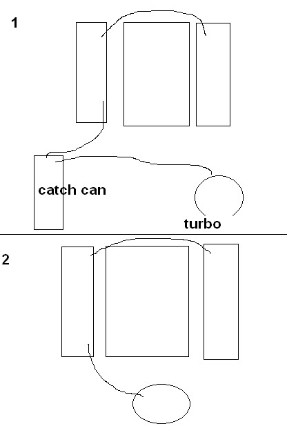
Neither one of the diagrams will provide the critical filtered fresh air needed to flush the nasty crap out of the crankcase, and your not tied into the intake manifold for the vacuum needed while not under boost. So no.
PM me your email & I'll send you every diagram you could need for your application.
PM me your email & I'll send you every diagram you could need for your application.
12-30-2009, 03:53 PM
#299
TECH Addict
iTrader: (16)
Join Date: Jul 2005
Location: Anchorage, ALASKA
Posts: 2,899
Likes: 0
Received 0 Likes
on
0 Posts

I think this is the one I need but Im confused because wouldnt it just be pulling constant vacuum from the turbo due to the venturi effect? Maybe I dont understand how this is getting clean air?