LS1/6/2 vs. LS3/92 vs. LS7 intake tract
 06-29-2009, 10:41 PM
#1
Launching!
Thread Starter
Join Date: Feb 2004
Location: California
Posts: 271
Likes: 0
Received 0 Likes
on
0 Posts

Spot the trend in the development (cathedral type - left, LS3/92 - center, LS7 - right).

From my perspective, the LS7 is far superior to the other heads due to the straighter "shot" to the intake valve. Also the higher port position provides a much smoother transition from the intake.
Comments?
From my perspective, the LS7 is far superior to the other heads due to the straighter "shot" to the intake valve. Also the higher port position provides a much smoother transition from the intake.
Comments?
 06-30-2009, 12:00 AM
#3
Launching!
Thread Starter
Join Date: Feb 2004
Location: California
Posts: 271
Likes: 0
Received 0 Likes
on
0 Posts
The port cross-section is not an issue as all variants taper the volume from the valve to the intake face. Skinny or fat is also not the issue (Personally I like somewhere in-between  ).
).
The main change that can be seen is to the floor of the intake tract. The change being that it is moving higher, reducing the short side radius at the valve. I believe this, and the intake, is the reason why the LS7 heads outperform most (if not all) aftermarket/ported cathedral heads in the higher RPM range.
Posted cropped shots due to confidentiality issues.
).The main change that can be seen is to the floor of the intake tract. The change being that it is moving higher, reducing the short side radius at the valve. I believe this, and the intake, is the reason why the LS7 heads outperform most (if not all) aftermarket/ported cathedral heads in the higher RPM range.
Posted cropped shots due to confidentiality issues.
06-30-2009, 12:20 AM
#4
The port cross-section is not an issue as all variants taper the volume from the valve to the intake face. Skinny or fat is also not the issue (Personally I like somewhere in-between ).
The main change that can be seen is to the floor of the intake tract. The change being that it is moving higher, reducing the short side radius at the valve. I believe this, and the intake, is the reason why the LS7 heads outperform most (if not all) aftermarket/ported cathedral heads in the higher RPM range.
Posted cropped shots due to confidentiality issues.
).The main change that can be seen is to the floor of the intake tract. The change being that it is moving higher, reducing the short side radius at the valve. I believe this, and the intake, is the reason why the LS7 heads outperform most (if not all) aftermarket/ported cathedral heads in the higher RPM range.
Posted cropped shots due to confidentiality issues.
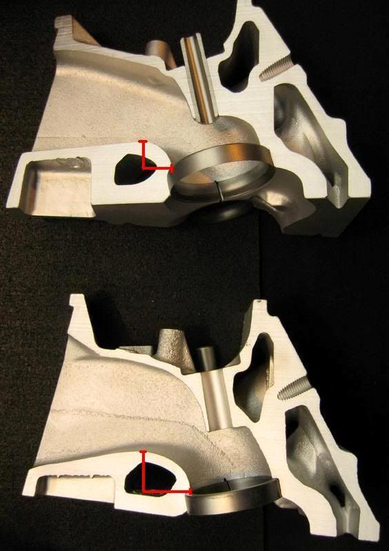
Here you can see the differences at the SSR, and how abrupt the L92 (top) is compare to the LS6 (bottom). If you were air traveling at high speed across the floor, which looks easier to follow?
06-30-2009, 03:57 AM
#5
Launching!
Thread Starter
Join Date: Feb 2004
Location: California
Posts: 271
Likes: 0
Received 0 Likes
on
0 Posts
Good points (and photos).
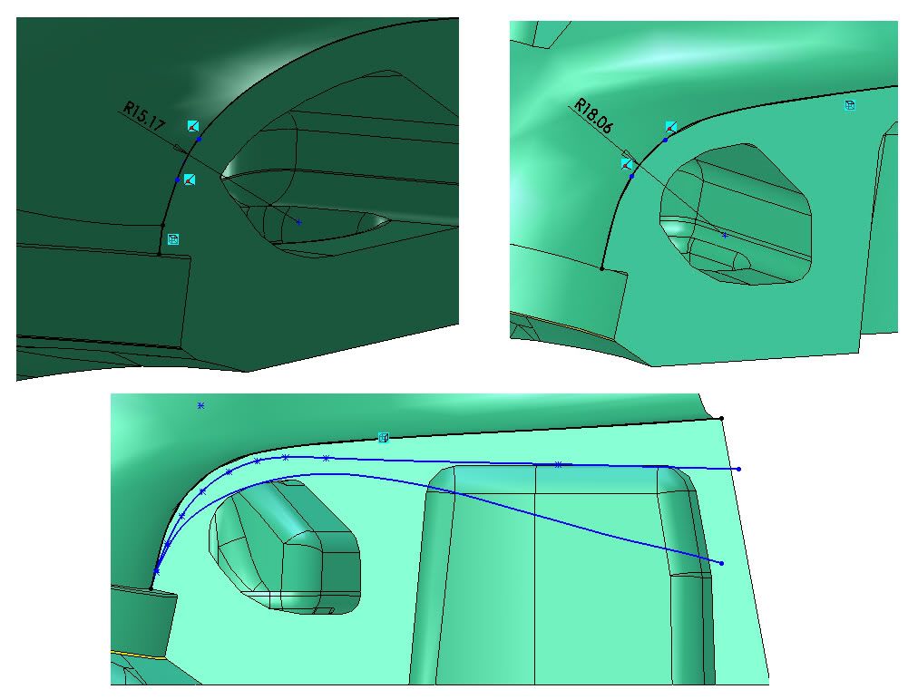
The cathederal port (top left) is a bit deceiving as the short side radius is not uniform - particularly down closer to the valve. I havent measured the LS3. LS7 is shown (top right)
My thoughts would be that the air flowing along the floor of the LS2 tract would separate significantly earlier than the other ports as the floor changes direction. This would create a partial vacuum resulting in less flow at the valve (imagine a jet of water entering the port along the floor of the 3 plotted below).
I would love to model it and my quad-core desktop is no slouch, but it is no supercomputer. A quality CFD on a basic intake manifold runner takes me 6hours+.
06-30-2009, 08:21 PM
#6
My theory here is that since the air is converging into a smaller cross section, the LS6 port can get away with that sharper radius only because it's so close to the valve (basically at the throat), and has a long sweeping radius leading up to that. A good exhaust valvejob does the same thing.
The LS7/L92, however, has that uniform radius which the air doesn't seem to like to stick to. That curved vane trailing the valeguide is meant to lay the air over onto itself and sort of push the air against the radius as it approaches the valve. AKA, The Oliver Twist.
On a further note, that last illustration helps show how straight the approach is to the valve. I think it's been called a "waterfall" or something, but the pathway for the air is as straight as possible feeding into the valve. This makes for excellent flow numbers, but the velocity characteristics suffer. It's almost blatantly obvious that two different people designed these ports and the criteria in which they did it...
07-01-2009, 01:01 AM
#7
Launching!
Thread Starter
Join Date: Feb 2004
Location: California
Posts: 271
Likes: 0
Received 0 Likes
on
0 Posts
On a further note, that last illustration helps show how straight the approach is to the valve. I think it's been called a "waterfall" or something, but the pathway for the air is as straight as possible feeding into the valve. This makes for excellent flow numbers, but the velocity characteristics suffer. It's almost blatantly obvious that two different people designed these ports and the criteria in which they did it...
I still hold the opinion that the LS7 is the best design of the three...
Trending Topics
07-01-2009, 08:18 AM
#8
Agreed. It would be interesting to know the history behind the port design and the thought processes at the time. It would also be nice to visualise the fluid flow at the "waterfall" using CFD plots.
I still hold the opinion that the LS7 is the best design of the three...
I still hold the opinion that the LS7 is the best design of the three...