When you click on links to various merchants on this site and make a purchase, this can result in this site earning a commission. Affiliate programs and affiliations include, but are not limited to, the eBay Partner Network.
what is the formula for piston instantaneous velocity ?
This is not what you're looking for:
Piston Mean Speed [ft/min] = RPM x stroke[inch] / 6
This is what you're looking for:
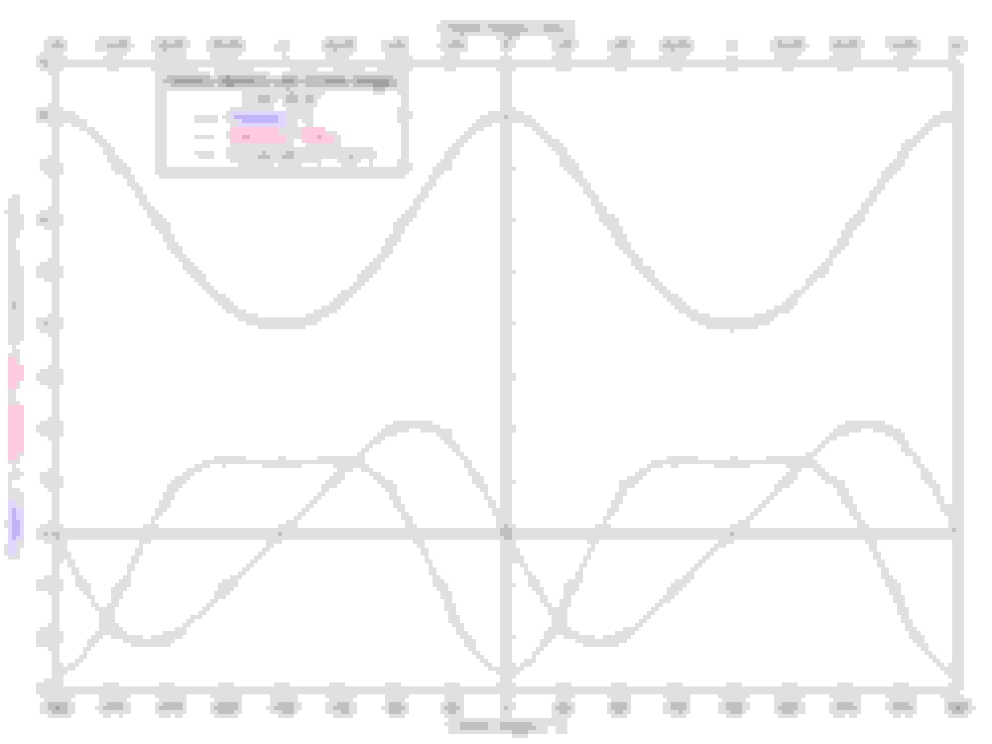
v(A) = -R.sin(A) - R�.sin(A).cos(A)/sqrt(L� - R�.sin�(A))
where:
v(A) = piston instantaneous velocity in [inch/rad] at A
A = crank angle in [radians] (0 = straight up = TDC)
R = crank radius in [inches] (center-to-center) = 1/2 x stroke
L = connecting rod length in [inches] (center-to-center)
see red curve in graph attached.
To convert v(A) in [inch/rad] to [inch/s] at some RPM you have to do this:
convert RPM to angular velocity w like this: w[rad/s] = 2.pi.RPM/60
then in v(A) replace A by wt and multiply v(A) by w to get v(wt) like this:
v(wt) = -w.R.sin(wt) - w.R�.sin(wt).cos(wt)/sqrt(L� - R�.sin�(wt))
this gives the instantaneous velocity in [inch/s] at time t[s] at any engine speed w[rad/s] where t=0 is TDC.
Last edited by joecar; May 22, 2017 at 10:00 AM.
Reason: corrections to units
Hi Joecar, good report with respect to an "on center" Piston Pin.
Would you make the same style of report with an "off-set" pin (OEM) as used in a LS-x engine ?
Would you make the same style of report with a reversed pin "offset " as I do fit at times with a LS-x engine ?
Hi Joe, we are now a team ?
YES, please visit with an appointment made by phone first.
I will show you my BAS progress.
Those here, ALL, who "speak" piston tech NEVER have stated the benefits of Pin Offset. (SAD)
YOUR HELP has shown this effect in an easy to read picture.
I use EAP to generate the same, a similar picture.
The MAX C.R. for Engine Knock Resistance IS effected by Pin Offset.
EXAMPLE : LS-427
1. This is a 4.1" stroke by 4.065" bore with LS-2 heads.
2. The C.R. is 12:1, a value that could scare a person with 93 octane.
3. The use of an "offset pin" piston WILL ADD Knock Resistance when in the OEM direction.
4. The use of an "offset pin" piston will allow the LS-2 port head to flow MORE air into the cylinder, with OEM direction.
EXAMPLE : LS-3 OEM with RaceTec Offset Piston.
1. The Hendrick head, the LS-3 head, flows the air required for a Cup Engine and WHEN "matched" to a non OEM piston offset will make better Torque.
2. The same is true with the Dynamic Compression, the piston will remain higher in the cylinder at a higher BMEP with an increase in Torque.
I believe YOUR WORK may answer a common asked question made by LS-1 Tech members.
For fun, I did this a while back. First I made the calculation on paper, then I wrote a small piece of software so I could find other rod/stroke/rpm more easily.
Enclosed is the program (requires VB runtime), the source code, and the initial paper calculation.
It isn't as advanced as what Joe posted, it just uses basic math based on rpm and angles/lengths.
Hi Kingtal0n,
Too much special case math obscures what is going on... you can generalize it, especially the derivatives wrt angle and wrt time... see this wiki I wrote a few years ago, it outlines the derivative math and it shows how to convert from angle to time using calculus identities (you could do the derivatives wrt time, but doing this is tedious, it comes out the same, and it is more fun to use the calculus identities).
See attached doc for non-zero offset (OEM offset would be negative)... if you insert those equations into a VB program with L, R, K as parameters, and run x from -360� (-2pi rad) to +360� (+2pi rad) you can get a nice plot of x, v, a.
I used a general purpose plotting tool called DPlot.
Hi Joe, it WAS confirmed in the above graphs. (yours)
Allow me to state : When the offset is on the throw side in the DOWN direction of crankshaft rotation, the effective compression will be HIGHER/intake port flow requirement HIGHER.
When the offset is normal, the throw side will be on the UP direction of crankshaft rotation with pin to the block center (RH not LH rotation), the effective compression will be LOWER/intake port flow requirement LOWER. (OEM)
Thus a high static C.R. AND small intake port WILL work better with the GM OEM designed inboard offset.
This will work for BOTH engine rotations. (LH/RH)
NOW what I DO NOT UNDERSTAND is NO Mention of this effect, your Joe's/King's fine work, with respect the "Effective Compression" thread ?
NOW what I DO NOT UNDERSTAND is NO Mention of this effect, your Joe's/King's fine work, with respect the "Effective Compression" thread ?
Lance
Nobody mentions that because any airflow differences due to a change in pin offset are well within a standard margin of error for our measurement tools. Manufacturers don't utilize an offset for performance; it is for cold engine NVH improvement.
HI Jake, my concern (1971) was to "fix" the Large Ports used in the BOSS 302 Ford emgine.
We used an offset piston pin location (opposite OEM) for that fix.
The piston "dwell" is better for a larger port (Boss 302) with results of Torque increase at ALL RPM AND an HP increase of 18-20 HP for a 500HP engine.
The OEM's DO consider Noise Vibration Harshness with MY report of their concern during my Camless Engine bench dyno tests.
As for manufactures concerns, they DO though there may be other requirements for their needs than peak power.
Lance, BTW MY dyno has an inlet air measurement turbine.
I see that you're responding to me, but I don't understand the relevance of really anything you're saying. It's all so far into left field i find myself wondering if you are responding here to a topic in another thread.
6 Common C5 Corvette Failures and What's Involved In Repairing Them
Slideshow: From wobbling harmonic balancers to failed EBCMs, these are the issues that define long-term C5 ownership and what repairs typically involve.
Retro Modern Bandit Pontiac Trans AM Comes With Burt Reynolds' Autograph
Slideshow: A modern Camaro transformed into a retro icon, this limited-run "Bandit" build blends nostalgia with brute force in a way few revivals manage.
Top 10 Greatest Cadillac V Series Performance Models Ever, Ranked
Slideshow: Cadillac didn't just crash the high-performance luxury vehicle party, it showed up loud, supercharged, and occasionally a little unhinged...
Coachbuilt N2A Anteros Is an LS2-Powered C6 Corvette In Italian Clothes
Slideshow: A one-off sports car that looks like a vintage Italian exotic-but hides a C6 Corvette underneath-just sold for the price of a new mid-engine Corvette.


 this is a very interesting topic.