99-02 odo, swapped OEM smd leds with white smd leds, +converting odo to OLED screen
 09-10-2014, 06:23 PM
#141
Teching In

Join Date: Sep 2014
Posts: 9
Likes: 0
Received 0 Likes
on
0 Posts
Thanks.
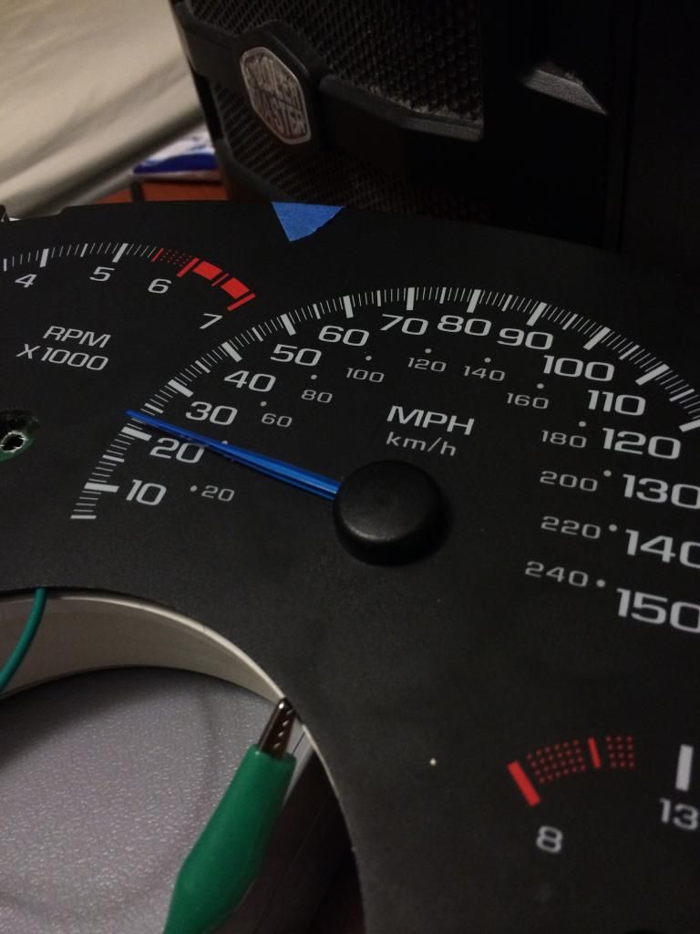
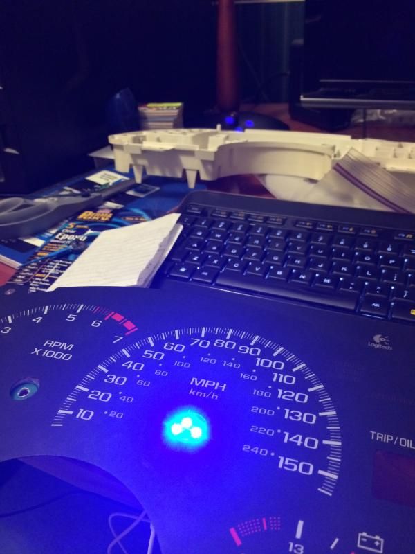
Not ready to show anything on the OLED screen, but Im getting other aspects of the cluster worked out. Namely the blue needles and the lighting. Since there's quite a bit of custom aspects of this cluster, the new gauge face is the last thing I will have made. In the meantime, I scraped off the blue tint on the back of a stock face and am using it for now.
Needles- It took alot of work to get the blue how I wanted. Benchmark was the VW Golf R color. First off was getting new needles. I didnt feel like spending alot of money on this, so I looked in GM's parts bin by going through a local u-pick junkyard. Turns out the 2000'ish Chevy Venture/Olds Silhouette minivans use the exact needles as the Camaro/Firebirds, except they are white. Downside, you cant get a full set of needles from one cluster, you need 2. The minivan clusters have a tach, speedo and 2 smaller gauges. The tach needles is smaller, so you need 2 speedo needles, and the 2 smaller gauge needles from each cluster to make the full set of 6 we need. Good thing for me this junkyard is u-pick in a true sense, they could care less if you take apart a cluster for the needles only. Went up to pay and the guy laughed and said have a nice day. Score...cost $0.
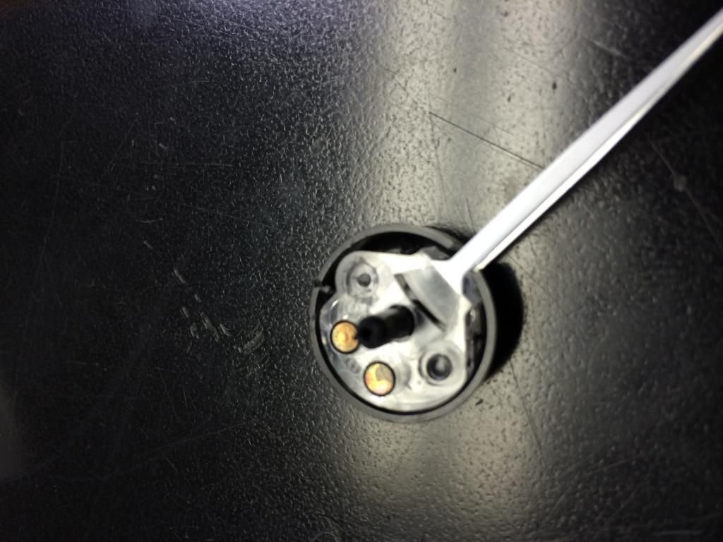
You do need to swap the black caps though with the F-car caps. On the minivan caps, the stems are much longer and the spindle hole is much smaller.
Getting the caps off is not a biggie. They are plastic welded on so you need to cut the smashed plastic cap off each post. Super easy as the plastic is really thin. To reapply a VERY small amount of epoxy and they will never come.
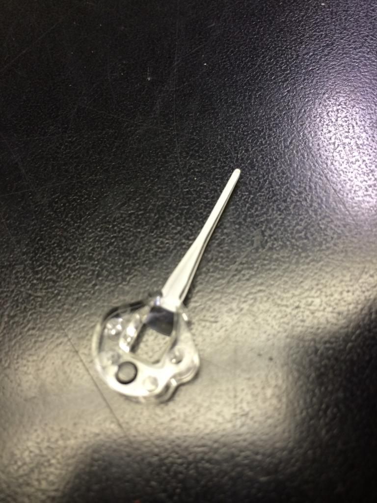
One cap cut off the post.
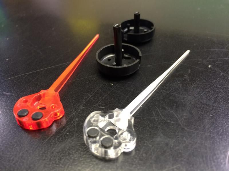
Comparison between Camaro and Venture Speedo needles diassembled.
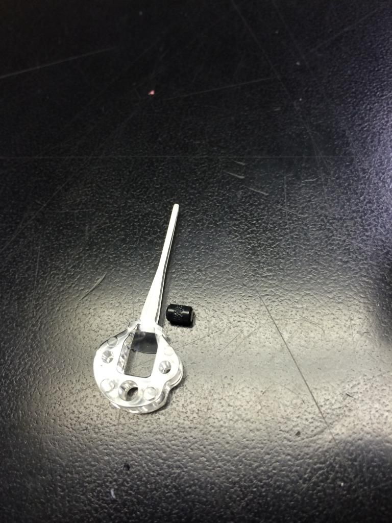
Heres the smaller needles. Note, the Venture needles dont come with the weight the Camaro has.
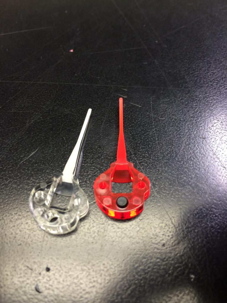
Sooo, you need to swap it over. Its stupid easy, just push the weight out of the Camaro needles and install into the Venture needle. You will need pliers to squeeze it in. The weights are splined and designed to be pressed in.
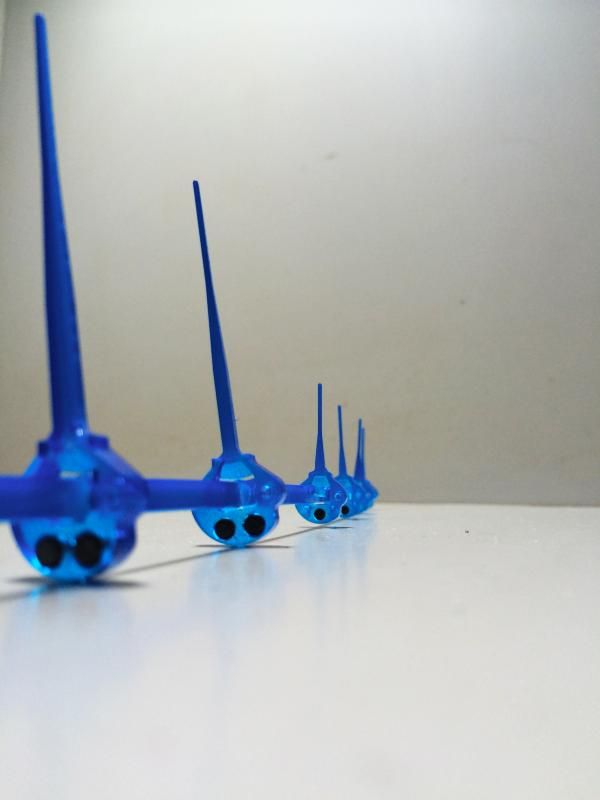
Done
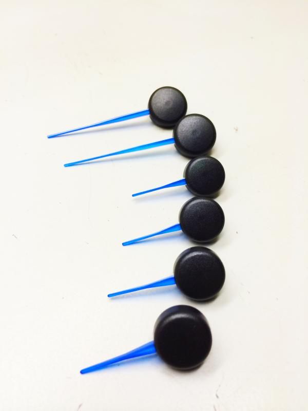
Now the mechanics are settled, time to paint. Took awhile to find the exact color I wanted. Settled on Tamiya transparent blue polycarbonate paint and Tamiya clearcoat.
Just ran a zip tie thru the holes on the center of each needles to they were stable to paint.
Because I could I weighed them, the painted needle weighs 1.5 grams just like the unpainted one.
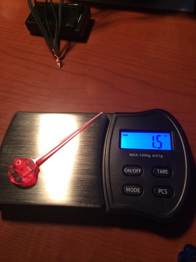
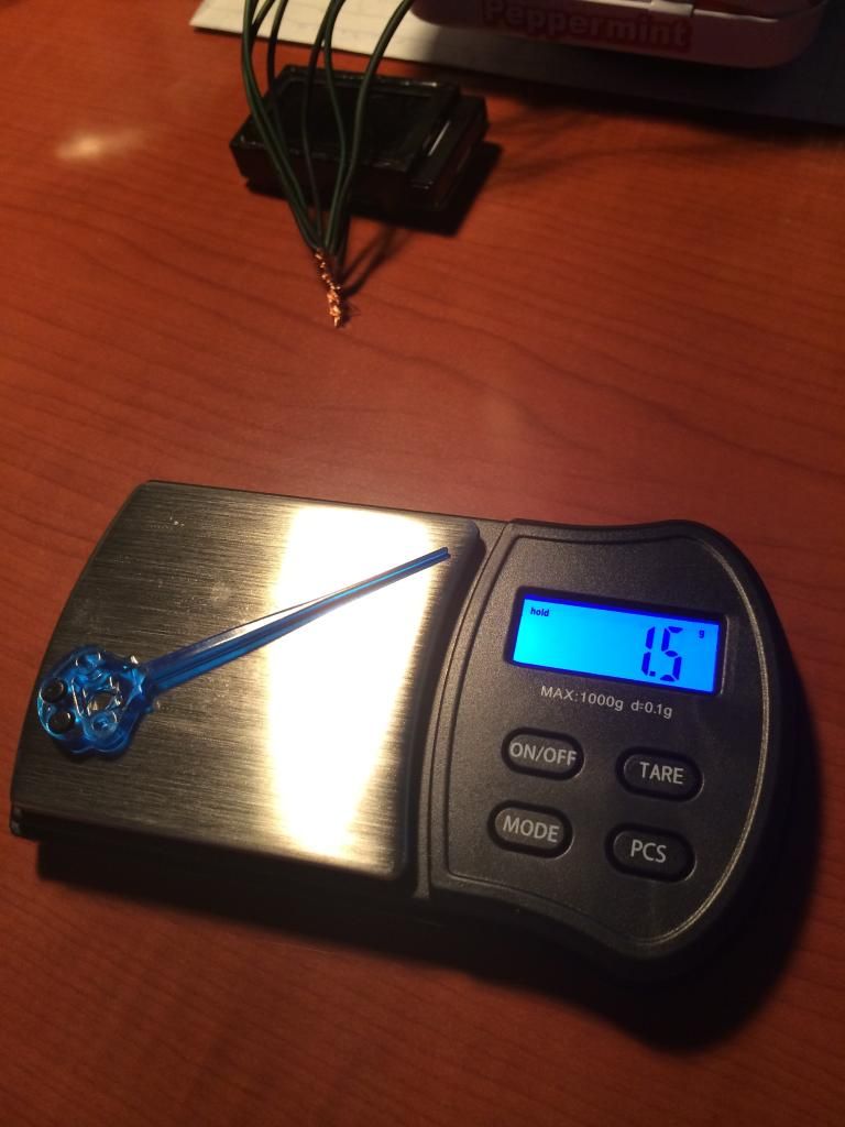
Done
Heres where it get a little interesting. I wanted to make the needle lighting independent to the backlighting. The stock light guides suck making the light distribution through the needles terrible. Time for a solution. I drilled out the area where the needles are.
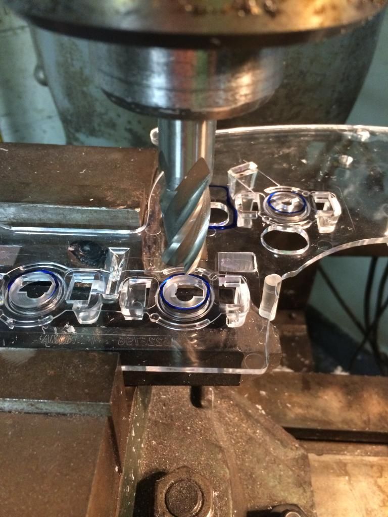
Next I made little circuit boards and used Osram plcc2 smd leds in true blue. The work is messy, theyre just proto's for light placement. For the finished products I will etch surface mount pcb's so it will nice and tidy and professionally done.
Lit up
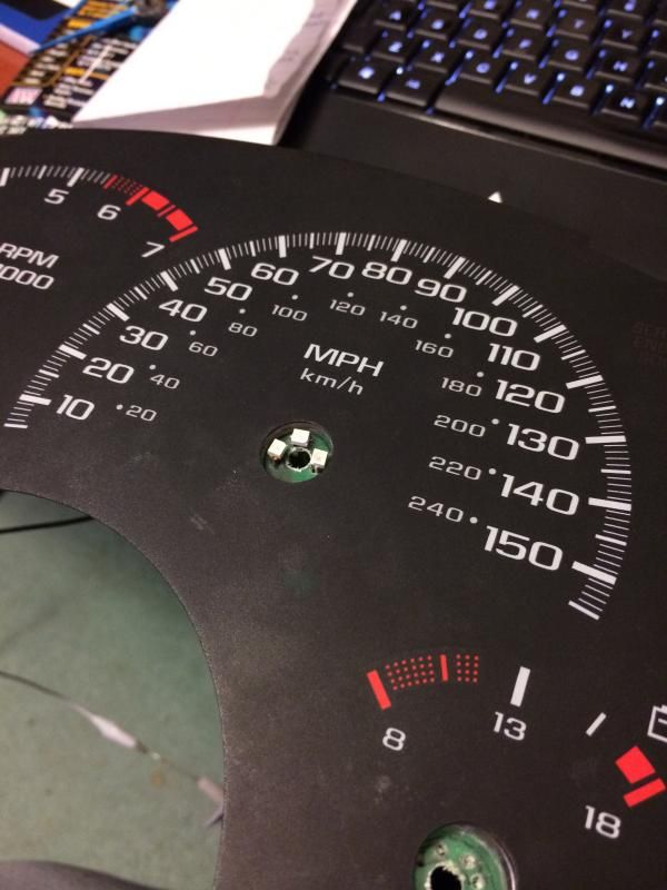
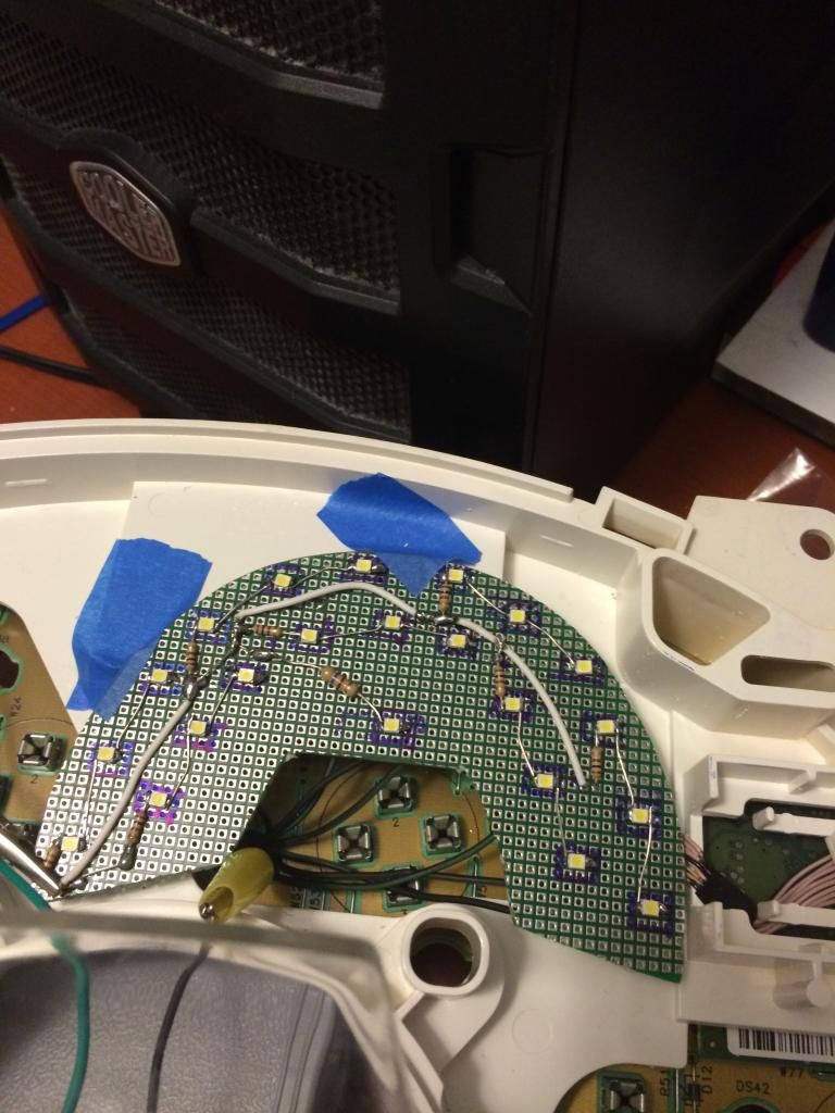
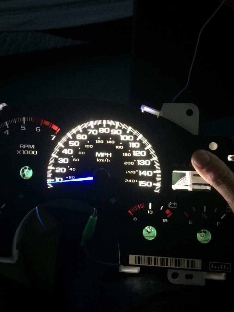
Then onto fabbing the main backlighting. Right now I only have the speedo done. Im doing all the gauges independent right now for led placement. The finished product though will be 1 very thin surface mount pcb (.062") That pcb will house the white backlighting, turn signal leds and all the re-located warning light leds.
Again, messy for the proto lol. I did not want to use this many LEDs, but the area is so slim its impossible to get the full potential spread of light these leds are capable of. Just playing around, if I was about 6" away I could light the whole speedo with 4 of these little leds and the light filter. Leds again are Osram plcc2 smds, this time in pure white, 5600 kelvin to be exact. Most of the white leds are 6500 kelvin and above, I didnt want the bluish white they make. These 5600K leds ended up being perfection, pure white, no bluish hue or yellowish hue.
Next step with the backlighting is making sure theres no hot or cold spots like the stock lighting. I also did not want blinding bright light. I used a Optix light filter from Plaskolite made for diffusing led light. Its a translucent white polycarbonate. It did its job perfectly.
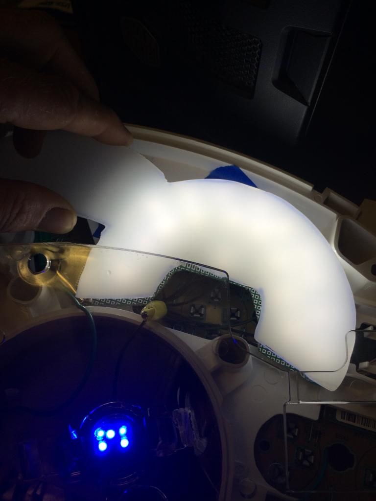
It looks kickass lit up. Not to bright , no hot or cold spots, the blue in the needle is super rich, bright and even all the way to the tip.
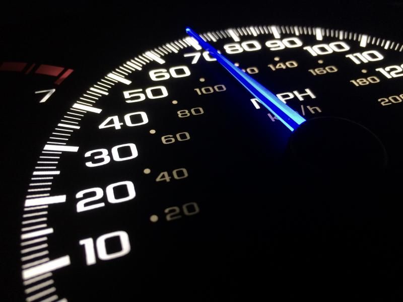
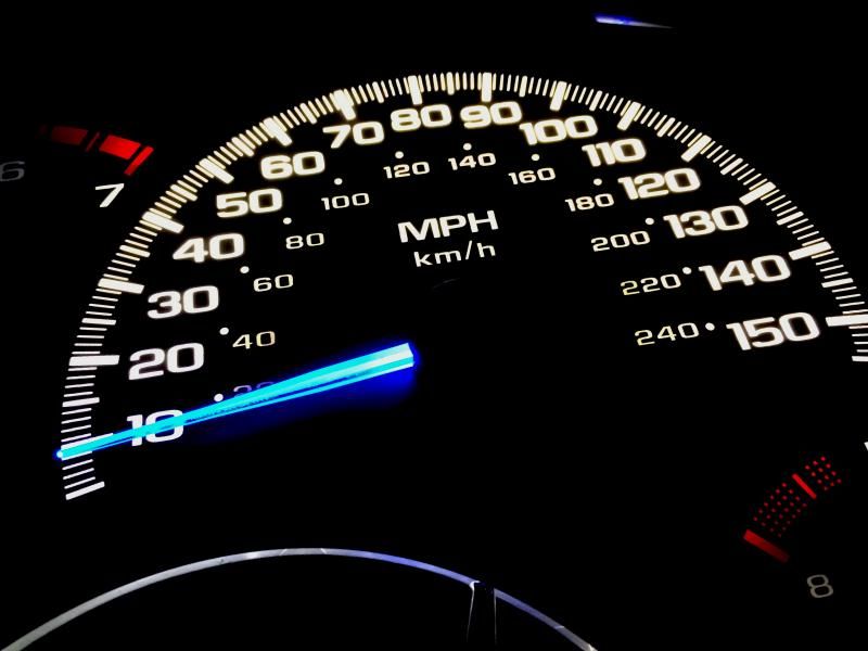
At this angle, my iphone cam is making the white look waaay brighter than it really is.
Not ready to show anything on the OLED screen, but Im getting other aspects of the cluster worked out. Namely the blue needles and the lighting. Since there's quite a bit of custom aspects of this cluster, the new gauge face is the last thing I will have made. In the meantime, I scraped off the blue tint on the back of a stock face and am using it for now.
Needles- It took alot of work to get the blue how I wanted. Benchmark was the VW Golf R color. First off was getting new needles. I didnt feel like spending alot of money on this, so I looked in GM's parts bin by going through a local u-pick junkyard. Turns out the 2000'ish Chevy Venture/Olds Silhouette minivans use the exact needles as the Camaro/Firebirds, except they are white. Downside, you cant get a full set of needles from one cluster, you need 2. The minivan clusters have a tach, speedo and 2 smaller gauges. The tach needles is smaller, so you need 2 speedo needles, and the 2 smaller gauge needles from each cluster to make the full set of 6 we need. Good thing for me this junkyard is u-pick in a true sense, they could care less if you take apart a cluster for the needles only. Went up to pay and the guy laughed and said have a nice day. Score...cost $0.
You do need to swap the black caps though with the F-car caps. On the minivan caps, the stems are much longer and the spindle hole is much smaller.
Getting the caps off is not a biggie. They are plastic welded on so you need to cut the smashed plastic cap off each post. Super easy as the plastic is really thin. To reapply a VERY small amount of epoxy and they will never come.
One cap cut off the post.

Comparison between Camaro and Venture Speedo needles diassembled.

Heres the smaller needles. Note, the Venture needles dont come with the weight the Camaro has.

Sooo, you need to swap it over. Its stupid easy, just push the weight out of the Camaro needles and install into the Venture needle. You will need pliers to squeeze it in. The weights are splined and designed to be pressed in.

Done

Now the mechanics are settled, time to paint. Took awhile to find the exact color I wanted. Settled on Tamiya transparent blue polycarbonate paint and Tamiya clearcoat.
Just ran a zip tie thru the holes on the center of each needles to they were stable to paint.

Because I could I weighed them, the painted needle weighs 1.5 grams just like the unpainted one.


Done


Heres where it get a little interesting. I wanted to make the needle lighting independent to the backlighting. The stock light guides suck making the light distribution through the needles terrible. Time for a solution. I drilled out the area where the needles are.

Next I made little circuit boards and used Osram plcc2 smd leds in true blue. The work is messy, theyre just proto's for light placement. For the finished products I will etch surface mount pcb's so it will nice and tidy and professionally done.

Lit up

Then onto fabbing the main backlighting. Right now I only have the speedo done. Im doing all the gauges independent right now for led placement. The finished product though will be 1 very thin surface mount pcb (.062") That pcb will house the white backlighting, turn signal leds and all the re-located warning light leds.
Again, messy for the proto lol. I did not want to use this many LEDs, but the area is so slim its impossible to get the full potential spread of light these leds are capable of. Just playing around, if I was about 6" away I could light the whole speedo with 4 of these little leds and the light filter. Leds again are Osram plcc2 smds, this time in pure white, 5600 kelvin to be exact. Most of the white leds are 6500 kelvin and above, I didnt want the bluish white they make. These 5600K leds ended up being perfection, pure white, no bluish hue or yellowish hue.

Next step with the backlighting is making sure theres no hot or cold spots like the stock lighting. I also did not want blinding bright light. I used a Optix light filter from Plaskolite made for diffusing led light. Its a translucent white polycarbonate. It did its job perfectly.

It looks kickass lit up. Not to bright , no hot or cold spots, the blue in the needle is super rich, bright and even all the way to the tip.


At this angle, my iphone cam is making the white look waaay brighter than it really is.

 :d rool:
  09-10-2014, 07:06 PM
#142

Thats for the compliments everyone.
09-11-2014, 08:24 AM
#143

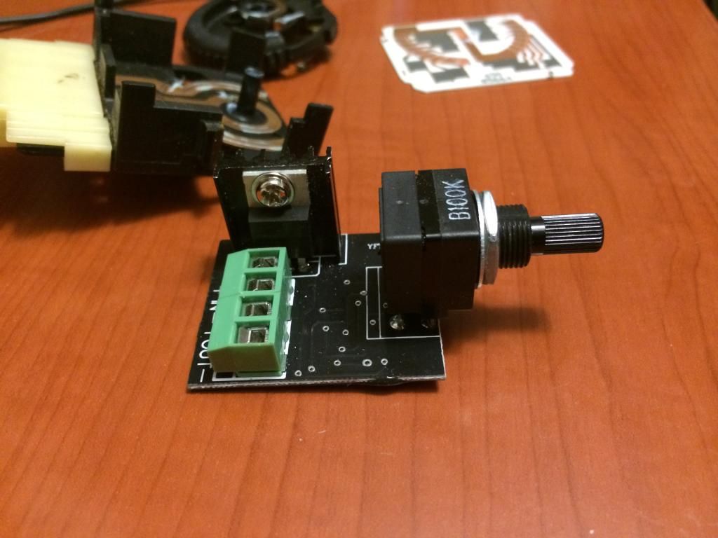
Did a bit of testing last night at work. The pwm circuit works flawlessly. It dims incandesents, leds and a mixture of the 2. It works 0-100%, I say that because a few dimmers on the market only will dim to 10% and full brightness at 90%. Still trying to come up with a solution that will keep it looking 100% like stock. Out dimmer switch is a design from when dinosaurs were still around, so its making it hard. I can take the oem dimmer wheel and easily fab that to the spline on the dimmer in the pwm circuit and mount so everything looks oem, but I have to come up with something to turn the interior lights on and off. Unlike our stock dimmer that is a dimmer and an off/on switch, the pwm circuit is just a dimmer.
Thats for the compliments everyone.
Thats for the compliments everyone.
09-11-2014, 09:09 AM
#144
Staging Lane
Join Date: Oct 2012
Location: Midland, VA
Posts: 54
Likes: 0
Received 0 Likes
on
0 Posts

This is awesome that you're actually doing this... I've wanted to, but haven't made it happen yet.
As far as using the stock dimmer, I assume it's just a voltage divider, which would be really easy to read with a microcontroller. Then you just need a way to PWM the LEDs from there, which there are a hundred different ways to do.
What processor are you going to use to drive your OLED display? Talk to the guy who's helping you program it, but I'll bet it could read the dimmer and dim the LEDs appropriately if it has the pins to spare. If not, look into Arduino stuff, fairly cheap, easy to program and tons of examples.
In any case, this is an awesome project! Let me know if I can be a help, I'm familiar with programming and a little bit of the hardware stuff too.
Also, I'm jealous of your design skills. Your graphics look sweet!
09-11-2014, 10:36 AM
#145
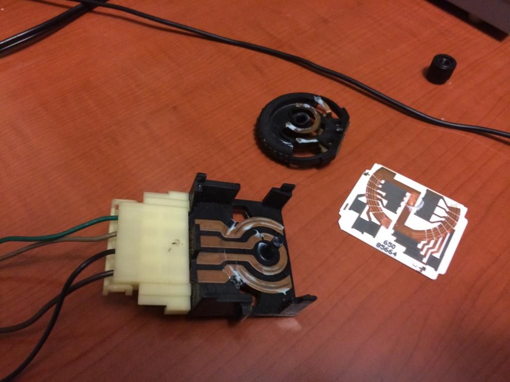
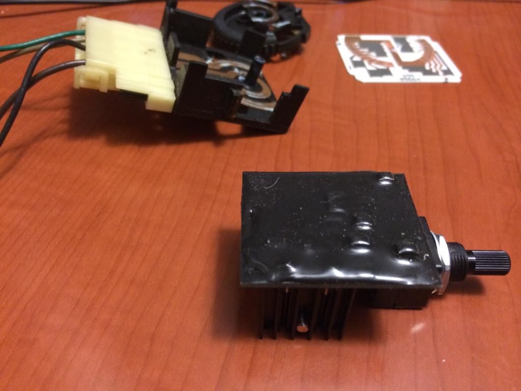
The stock dimmer is like a pass thru. My original plan was to mod the pwm circuit into the stock assembly, and I still am to some extent. My inputs for the pwm circuit are coming from the green and brown wire from the stock dimmer. The black and grey wire are for turning the dome light on.
Heres the stock switch taken apart. As you can see its not mod friendly at all.
I was going to make my own 555 timer circuit, etch the boards and all, but I given my limited time I really wanted to just buy something and be done with it, I have enough fabbing elsewhere Heres what I got. Its from marinebeam. Its just a simple 555 timer circuit rated for 8 amps( well withing the stock interior illumination circuit) It was a little pricey at $25, but they warranty it and its not some unknown china junk. Get what ya pay for.
I was kind of mad to see the underside is slathered in black epoxy=no modifying it
I am not sure of the processor yet. I will find soon as were about to start programming. Trying to keep everything as simple as possible. Same with the dimmer, I thought about using a arduino, but this simple little dimmer will easily handle all the interior lights. So, I am going to leave it at that for now. Down the road Im going eliminate all the OEM wiring in my car and replace with isis can bus wiring, then well get into more custom circuit stuff. Thanks for the compliments and offer of help, if I get hung up anywhere I'll hit ya up man.
Heres the stock switch taken apart. As you can see its not mod friendly at all.

I was going to make my own 555 timer circuit, etch the boards and all, but I given my limited time I really wanted to just buy something and be done with it, I have enough fabbing elsewhere
Heres what I got. Its from marinebeam. Its just a simple 555 timer circuit rated for 8 amps( well withing the stock interior illumination circuit) It was a little pricey at $25, but they warranty it and its not some unknown china junk. Get what ya pay for. 
I was kind of mad to see the underside is slathered in black epoxy=no modifying it

I am not sure of the processor yet. I will find soon as were about to start programming. Trying to keep everything as simple as possible. Same with the dimmer, I thought about using a arduino, but this simple little dimmer will easily handle all the interior lights. So, I am going to leave it at that for now. Down the road Im going eliminate all the OEM wiring in my car and replace with isis can bus wiring, then well get into more custom circuit stuff. Thanks for the compliments and offer of help, if I get hung up anywhere I'll hit ya up man.
09-11-2014, 12:24 PM
#146
Staging Lane
Join Date: Oct 2012
Location: Midland, VA
Posts: 54
Likes: 0
Received 0 Likes
on
0 Posts
Yeah, modding that factory switch look like a pain. You could certainly read it's output though if you wanted to go with factory controls down the road.
I hadn't heard of that Isis system before, looks pretty cool. Be careful though, once you get your feet wet programming you may want to build the whole system yourself instead of spending $1k on a prebuilt system
I hadn't heard of that Isis system before, looks pretty cool. Be careful though, once you get your feet wet programming you may want to build the whole system yourself instead of spending $1k on a prebuilt system
 09-19-2014, 10:02 AM
#150
On The Tree

Join Date: Jun 2013
Posts: 116
Likes: 0
Received 0 Likes
on
0 Posts
It would be amazing to have a full Digital Cluster like the Cadillac CTS... Im actually wondering if there's any way to connect that cluster to the camaro ECU? just like you did with the small screen but ten times bigger hehehe...
btw this is probably the smallest and most awesome mod I ever seen!
btw this is probably the smallest and most awesome mod I ever seen!
 09-20-2014, 01:28 AM
#152
Thanks for the compliments
SesiomSummers- The short answer is yes, it would be possible to create a TFT full gauge cluster display similar to the new Cadillacs. The unfortunate downside is the immense complexity of such a project. As a graphic designer I would have no problem designing the screens, flash based animations and functionality. However, the programming of a multi layered interface like a gauge cluster would be well well well beyond my scope. Once you start adding features and multiple functions it get quite complicated real quick, and the parts costs get alot more expensive as well. GM and any other OEM's use larger teams of people when designing these content and feature rich displays, as they are very complex. In contrast, the screen Im doing at a hobbyist level is rather simple. It has a fade in/out splash image at start up, then is a black background with white text. The ram requirements are quite minimal. The font converter/generator, the cpu and and such are freescale.
We will see how much my interest is held once this project is complete. Right now Im having fun with it and could see myself pursuing more complex projects with the software based displays.
Just got word today that circuit boards shipped yesterday. Hopefully some powered up images to come real soon. Its gonna be pretty sweet to see it come to life on the actual OLED module screen rather than the PC screen.
09-20-2014, 02:08 AM
#153
Teching In
Join Date: Sep 2014
Posts: 9
Likes: 0
Received 0 Likes
on
0 Posts
Thanks for the compliments
SesiomSummers- The short answer is yes, it would be possible to create a TFT full gauge cluster display similar to the new Cadillacs. The unfortunate downside is the immense complexity of such a project. As a graphic designer I would have no problem designing the screens, flash based animations and functionality. However, the programming of a multi layered interface like a gauge cluster would be well well well beyond my scope. Once you start adding features and multiple functions it get quite complicated real quick, and the parts costs get alot more expensive as well. GM and any other OEM's use larger teams of people when designing these content and feature rich displays, as they are very complex. In contrast, the screen Im doing at a hobbyist level is rather simple. It has a fade in/out splash image at start up, then is a black background with white text. The ram requirements are quite minimal. The font converter/generator, the cpu and and such are freescale.
We will see how much my interest is held once this project is complete. Right now Im having fun with it and could see myself pursuing more complex projects with the software based displays.
Just got word today that circuit boards shipped yesterday. Hopefully some powered up images to come real soon. Its gonna be pretty sweet to see it come to life on the actual OLED module screen rather than the PC screen.
SesiomSummers- The short answer is yes, it would be possible to create a TFT full gauge cluster display similar to the new Cadillacs. The unfortunate downside is the immense complexity of such a project. As a graphic designer I would have no problem designing the screens, flash based animations and functionality. However, the programming of a multi layered interface like a gauge cluster would be well well well beyond my scope. Once you start adding features and multiple functions it get quite complicated real quick, and the parts costs get alot more expensive as well. GM and any other OEM's use larger teams of people when designing these content and feature rich displays, as they are very complex. In contrast, the screen Im doing at a hobbyist level is rather simple. It has a fade in/out splash image at start up, then is a black background with white text. The ram requirements are quite minimal. The font converter/generator, the cpu and and such are freescale.
We will see how much my interest is held once this project is complete. Right now Im having fun with it and could see myself pursuing more complex projects with the software based displays.
Just got word today that circuit boards shipped yesterday. Hopefully some powered up images to come real soon. Its gonna be pretty sweet to see it come to life on the actual OLED module screen rather than the PC screen.
09-20-2014, 05:15 AM
#154
On The Tree
Join Date: Jun 2013
Posts: 116
Likes: 0
Received 0 Likes
on
0 Posts
Thanks for the compliments
SesiomSummers- The short answer is yes, it would be possible to create a TFT full gauge cluster display similar to the new Cadillacs. The unfortunate downside is the immense complexity of such a project. As a graphic designer I would have no problem designing the screens, flash based animations and functionality. However, the programming of a multi layered interface like a gauge cluster would be well well well beyond my scope. Once you start adding features and multiple functions it get quite complicated real quick, and the parts costs get alot more expensive as well. GM and any other OEM's use larger teams of people when designing these content and feature rich displays, as they are very complex. In contrast, the screen Im doing at a hobbyist level is rather simple. It has a fade in/out splash image at start up, then is a black background with white text. The ram requirements are quite minimal. The font converter/generator, the cpu and and such are freescale.
We will see how much my interest is held once this project is complete. Right now Im having fun with it and could see myself pursuing more complex projects with the software based displays.
Just got word today that circuit boards shipped yesterday. Hopefully some powered up images to come real soon. Its gonna be pretty sweet to see it come to life on the actual OLED module screen rather than the PC screen.
SesiomSummers- The short answer is yes, it would be possible to create a TFT full gauge cluster display similar to the new Cadillacs. The unfortunate downside is the immense complexity of such a project. As a graphic designer I would have no problem designing the screens, flash based animations and functionality. However, the programming of a multi layered interface like a gauge cluster would be well well well beyond my scope. Once you start adding features and multiple functions it get quite complicated real quick, and the parts costs get alot more expensive as well. GM and any other OEM's use larger teams of people when designing these content and feature rich displays, as they are very complex. In contrast, the screen Im doing at a hobbyist level is rather simple. It has a fade in/out splash image at start up, then is a black background with white text. The ram requirements are quite minimal. The font converter/generator, the cpu and and such are freescale.
We will see how much my interest is held once this project is complete. Right now Im having fun with it and could see myself pursuing more complex projects with the software based displays.
Just got word today that circuit boards shipped yesterday. Hopefully some powered up images to come real soon. Its gonna be pretty sweet to see it come to life on the actual OLED module screen rather than the PC screen.
09-20-2014, 09:59 AM
#155
I really would advise not spending the money, it would be a really expensive paper weight Im afraid. The can bus electronics in the newer cars are vastly different and not compatible with the traditional electronics in our cars. The CTS cluster is part of a system that well integrated with CUE. I would suggest something like a traqmate cluster.
09-28-2014, 11:20 PM
#156
The stock dimmer is like a pass thru. My original plan was to mod the pwm circuit into the stock assembly, and I still am to some extent. My inputs for the pwm circuit are coming from the green and brown wire from the stock dimmer. The black and grey wire are for turning the dome light on.
I was going to make my own 555 timer circuit, etch the boards and all, but I given my limited time I really wanted to just buy something and be done with it, I have enough fabbing elsewhere Heres what I got. Its from marinebeam. Its just a simple 555 timer circuit rated for 8 amps( well withing the stock interior illumination circuit) It was a little pricey at $25, but they warranty it and its not some unknown china junk. Get what ya pay for.
I am not sure of the processor yet. I will find soon as were about to start programming. Trying to keep everything as simple as possible. Same with the dimmer, I thought about using a arduino, but this simple little dimmer will easily handle all the interior lights. So, I am going to leave it at that for now. Down the road Im going eliminate all the OEM wiring in my car and replace with isis can bus wiring, then well get into more custom circuit stuff. Thanks for the compliments and offer of help, if I get hung up anywhere I'll hit ya up man.
I was going to make my own 555 timer circuit, etch the boards and all, but I given my limited time I really wanted to just buy something and be done with it, I have enough fabbing elsewhere
Heres what I got. Its from marinebeam. Its just a simple 555 timer circuit rated for 8 amps( well withing the stock interior illumination circuit) It was a little pricey at $25, but they warranty it and its not some unknown china junk. Get what ya pay for. I am not sure of the processor yet. I will find soon as were about to start programming. Trying to keep everything as simple as possible. Same with the dimmer, I thought about using a arduino, but this simple little dimmer will easily handle all the interior lights. So, I am going to leave it at that for now. Down the road Im going eliminate all the OEM wiring in my car and replace with isis can bus wiring, then well get into more custom circuit stuff. Thanks for the compliments and offer of help, if I get hung up anywhere I'll hit ya up man.
I briefly looked into this ISIS wiring system. I'm not sure I fully grasp the purpose of it. Is it something that's meant to either piggyback onto or replace our stock interior/body wiring with something more updated/sophisticated? Can this system communicate with the CAN BUS systems in newer vehicles like Corvettes etc?
To get a better idea of the applications and capabilities of this thing, what kind of things have you had in mind/tossed around in your head in regards to what you would attempt to do or achieve with this wiring system. What does it let you do that you couldn't do before?
I really would advise not spending the money, it would be a really expensive paper weight Im afraid. The can bus electronics in the newer cars are vastly different and not compatible with the traditional electronics in our cars. The CTS cluster is part of a system that well integrated with CUE. I would suggest something like a traqmate cluster.
How do you know so much about the hardware and software GM used in these cars (Hardware used, type of data, programming etc) and where can one learn more about it? These are exactly the types of projects that interest me the most and I'd like to get deeper into it.
Thanks!
09-30-2014, 05:00 AM
#157
Question about this.
I briefly looked into this ISIS wiring system. I'm not sure I fully grasp the purpose of it. Is it something that's meant to either piggyback onto or replace our stock interior/body wiring with something more updated/sophisticated? Can this system communicate with the CAN BUS systems in newer vehicles like Corvettes etc?
I briefly looked into this ISIS wiring system. I'm not sure I fully grasp the purpose of it. Is it something that's meant to either piggyback onto or replace our stock interior/body wiring with something more updated/sophisticated? Can this system communicate with the CAN BUS systems in newer vehicles like Corvettes etc?
To get a better idea of the applications and capabilities of this thing, what kind of things have you had in mind/tossed around in your head in regards to what you would attempt to do or achieve with this wiring system. What does it let you do that you couldn't do before?
If your curious look more into it and form your own opinion. Look more into the pro touring type forums for better info. Fcar specific searches is not gonna yeild much of anything. Also look up project snowball that GMHTP did. It was a really well written in depth tech series, part of which was replacing the oem harness with isis.
How do you know so much about the hardware and software GM used in these cars (Hardware used, type of data, programming etc) and where can one learn more about it? These are exactly the types of projects that interest me the most and I'd like to get deeper into it.
Thanks!
Thanks!
Hope that helps a bit. Sorry for the pretty basic explanations, its the end of the day for me so I'm pretty scatter brained and ready to sleep
