
99-02 odo, swapped OEM smd leds with white smd leds, +converting odo to OLED screen
 12-03-2014, 02:08 AM
#181

Wow, this is absolutely amazing. Excellent work!
Hopefully you don't mind me asking, what micro controller are you running this on? I was trying to get a closer look at whatever ~64 pin? micro controller you are running this on (on the main board).
I was considering making something similar to this for myself so I can customize it just how I want it. Even if you aren't willing to share your source code so I could modify/add features, I would still be interested in buying this just for the hardware + board layout, and then write my own program if necessary.
Any info you are willing to share would be awesome. Keep up the excellent work!
+Subscribed
 12-03-2014, 03:41 PM
#182

Wow, this is absolutely amazing. Excellent work!
Hopefully you don't mind me asking, what micro controller are you running this on? I was trying to get a closer look at whatever ~64 pin? micro controller you are running this on (on the main board).
I was considering making something similar to this for myself so I can customize it just how I want it. Even if you aren't willing to share your source code so I could modify/add features, I would still be interested in buying this just for the hardware + board layout, and then write my own program if necessary.
Any info you are willing to share would be awesome. Keep up the excellent work!
+Subscribed
Hopefully you don't mind me asking, what micro controller are you running this on? I was trying to get a closer look at whatever ~64 pin? micro controller you are running this on (on the main board).
I was considering making something similar to this for myself so I can customize it just how I want it. Even if you aren't willing to share your source code so I could modify/add features, I would still be interested in buying this just for the hardware + board layout, and then write my own program if necessary.
Any info you are willing to share would be awesome. Keep up the excellent work!
+Subscribed

The cpu is a freescale 9s12g. The data sheet for it is on freescales site if you want see the full specs. I got 2 for free as you can request samples. The code I dont mind sharing when its all sorted out. When this is complete feel free to pm and we can discuss building one for you. A friend of mine that is doing the programming and that designed the boards left a bit room open for customization and more options like switchable modes. I'm a graphic designer and am doing all the visual screen design, images ect. so I am not completely versed on the technical aspects. Im learning pretty fast though.
12-04-2014, 06:33 AM
#183

Thank you
The cpu is a freescale 9s12g. The data sheet for it is on freescales site if you want see the full specs. I got 2 for free as you can request samples. The code I dont mind sharing when its all sorted out. When this is complete feel free to pm and we can discuss building one for you. A friend of mine that is doing the programming and that designed the boards left a bit room open for customization and more options like switchable modes. I'm a graphic designer and am doing all the visual screen design, images ect. so I am not completely versed on the technical aspects. Im learning pretty fast though.
The cpu is a freescale 9s12g. The data sheet for it is on freescales site if you want see the full specs. I got 2 for free as you can request samples. The code I dont mind sharing when its all sorted out. When this is complete feel free to pm and we can discuss building one for you. A friend of mine that is doing the programming and that designed the boards left a bit room open for customization and more options like switchable modes. I'm a graphic designer and am doing all the visual screen design, images ect. so I am not completely versed on the technical aspects. Im learning pretty fast though.
What was your total cost on the boards and hardware? I know you had a few revisions, but what is the approximate cost to build a new unit from scratch based on your latest design? That would let me know if this is something I should be fitting into my upgrade budget, or if this is something I should plan on just drooling over and envying you on
 12-04-2014, 09:21 AM
#184
I will try to put together some costs. At this point im not sure as were swapping his circuit board design and programmer skills for my design work. Im doing the graphic interfece for his 240x320 tft DIC very similar to whats in the new Audi's with a ton more features and functions than mine. I will say I think the only real cost he has is the circuit board manufacturing. He did all the pcb design in eagle and installed all the components himself as opposed to having it done when the boards were made. The boards were made in Germany. The cpu was free as it was a sample from freescale. The oled module was $45. All the other small parts like connectors, transitors, capacitors, resistors and such are very cheap. The c5 vette air temp sensor is anywhere from $8-25 depending where you buy. So it is fesible to do on the somewhat cheap.
12-04-2014, 10:00 AM
#185
I will try to put together some costs. At this point im not sure as were swapping his circuit board design and programmer skills for my design work. Im doing the graphic interfece for his 240x320 tft DIC very similar to whats in the new Audi's with a ton more features and functions than mine. I will say I think the only real cost he has is the circuit board manufacturing. He did all the pcb design in eagle and installed all the components himself as opposed to having it done when the boards were made. The boards were made in Germany. The cpu was free as it was a sample from freescale. The oled module was $45. All the other small parts like connectors, transitors, capacitors, resistors and such are very cheap. The c5 vette air temp sensor is anywhere from $8-25 depending where you buy. So it is fesible to do on the somewhat cheap.
I'd have no issue in soldering on the components if I knew what they are and where they go. I have no idea on what a custom board like that would cost.
EDIT: Eh, on second thought that looks like some pretty intricate work. I've soldered stuff in the past, like the PWM kit that I bought to work as a dimmer, but that wasn't nearly as intricate as this. I don't know that I could handle this with my "hack" soldering skills.
12-04-2014, 10:26 AM
#186
With stuff this small I use solder paste and a hot air gun. Otherwise a superfine tip with a machine that will allow lower temps and a magnifying glass works, the solder resist will keep the solder on the pad. Key is not get it too hot. I had to relocate a resistor on the OLED foil, now that was a bit rediculous


 12-15-2014, 11:14 AM
#191
Thanks guys.
I wont be doing red low light, with mine I am just using a solid black background with bright white text. However, given that screen is color it is possible for the background and text to be any color combination you wish. Once this is all said and done and installed in my car and I am more familiar with the coding, I can mix up the bg/fg colors if someone wanted to see something specific.
Heres a vid of the flicker fixed when the splash screen opens. Also added a soft fade in, rather than a instant on. Onto to working on the main screen text, and selecting a module to use for the compass. In the vid it appears the image is flickering, which looking at it in person it does not flicker at all. I can only assume its the same scenario when a camera is filming any led type lighting that it pulse width modulated, its just looks to be flickering on film.
 12-16-2014, 09:24 AM
#194

Thanks man, I appreciate the words.
99ss - I'm afraid not yet. A revision had to be made on one of the boards, so currently waiting for them to come back again from the pcb house. Hopefully no more revision need to be made. Designing and building something like this from nothing has proven to be a pretty lengthy adventure.
99ss - I'm afraid not yet. A revision had to be made on one of the boards, so currently waiting for them to come back again from the pcb house. Hopefully no more revision need to be made. Designing and building something like this from nothing has proven to be a pretty lengthy adventure.
12-17-2014, 05:54 PM
#197
Thanks for the compliments, much appreciated. In my car its definately not plug and play. The plx gauge incorporated in the cluster needs to be plugged into the data port. Im creating a new aldl port under my dash separate from the stock the plug so it is hidden. To get the temp input im fabbing a c5 vette ambient air sensor into the driverside headlamp bracket. The compass module which is roughly the size of a sugar cube will mount under the top dash shelf. I need to grab an input from speed sensor wire going to the pcm. All those wires will route to 1 external(separate from the cluster) module(similar in function to an OEM bcm)thats feeds the OLED in the cluster those inputs. Plus the pulse width module board im wiring into the dimmer circuit so everything dims properly. I dunno, to me this all very easy stuff but its definately not plug and play. Ill know more when this is all complete and tested how it would/could be packaged to sell. Thank god my friend Oliver is brilliant with electronics because this got 1000x's more involed that I initially had invisioned. I was thinking "a" custom circuit board with the input data going to it, not the 4 separate circuit boards it turned out to be.
Here another vid. Main screen populated with text. The text still needs alot of work with sizing but this proves it works, thank god

Here another vid. Main screen populated with text. The text still needs alot of work with sizing but this proves it works, thank god
12-19-2014, 04:38 AM
#198
Wow this just keeps looking better and better. Its very fun to see the progress updates as you go.
If you are looking for a speed sensor wire you can pull a nearby one from the factory radio harness. The Dark Green/White wire should be the speed sensor. Its pin 16 on the white 10 pin stereo connector. See connector labeled C3 in the Monsoon Audio FAQ. If you already have a non-factory stereo (likely) then you can just use the wiring harness adapter and not have to cut/splice into the factory harness at all. This was used for the speed compensated volume if I remember correctly. It's Likely that whatever wiring harness adapter you are using may not be populated on that pin, but you can just add a new pin in that spot if you have extras, or move one from a different unused spot on the adapter.
Pin B8 on the main instrument cluster connector (34-pin) should also be the speed sensor, its the same color (Dark Green/White) as its actually wired in the same circuit as the stereo connector. I cant recall if you were planning hooking directly into the cluster connector or doing a pass through with it or anything like that. The female version of the connector is Delphi 12065803 and can be bought from gmpartsdirect for a couple dollars or from any other delphi distributor that carries it. The *board mount* male version that mates with that is supposedly Delphi 12066537
Last edited by HypervisorX; 12-19-2014 at 05:30 AM. Reason: Added other location and connector info
The following users liked this post:
JakeRobb (12-16-2020)
12-22-2014, 09:00 PM
#199
Thanks for the compliments and thanks for the info. Great to know the part numbers for the cluster connector. I had planned on using the speed sensor wire for the radio. Having the wire on the radio harness makes it easy.
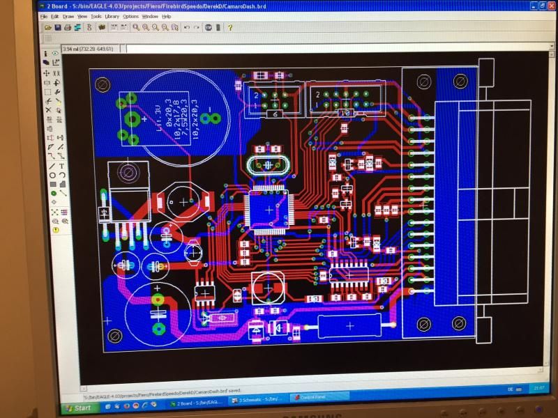
Heres a few image updates for anyone following the electrical design part. The first set of circuit boards were just dummy boards for testing purposes and to verify it all works. This is the new main board, which combined the 2 larger test boards into one.
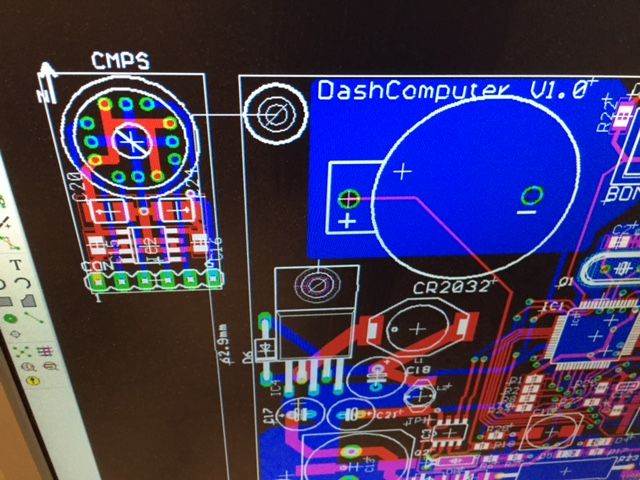
Here is the board for the compass module, its the small design under the cmps text heading. Its about the size of 2 pennies and I plan on mounting on the flat metal shelf area at the base of the windshield under the upper dash pad.
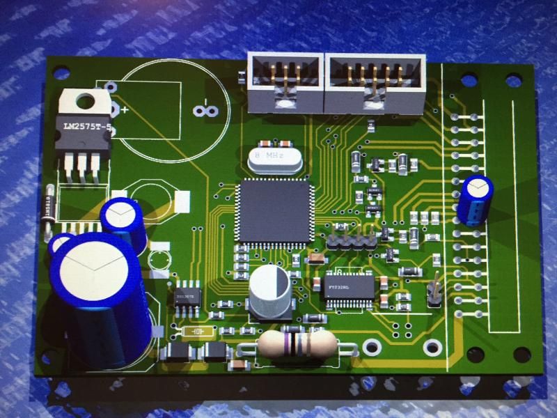
Here is a 3d render of the new main board. It didnt render entirely accurate though. It left out the usb connector, the main delphi metripack 32-pin connector and a couple small items are out of place like the little blue capacitor sitting on top of the connector pads.
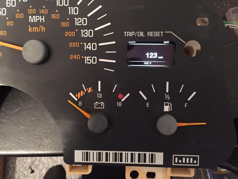
Lastly, heres the OLED sitting in a spare firebird cluster. The hole hasnt been resized in the gauge face so it gives and idea to the new size of the screen. Its about the same width as oem but it is taller, as you can see it cuts the top and bottom off the new screen. Also text on the OLED has not been corrected yet so it still to small.
 12-23-2014, 10:54 AM
#200
Staging Lane
Join Date: Oct 2012
Location: Midland, VA
Posts: 54
Likes: 0
Received 0 Likes
on
0 Posts

Man, that little OLED really looks great sitting in the cluster!
Wow, two versions of the PCB? Are you aiming to finish this into a commercial product? Seems like a lot of effort if you are only building one.
Wow, two versions of the PCB? Are you aiming to finish this into a commercial product? Seems like a lot of effort if you are only building one.