When you click on links to various merchants on this site and make a purchase, this can result in this site earning a commission. Affiliate programs and affiliations include, but are not limited to, the eBay Partner Network.
The Sonnax reverse abuse bore plug is a nice piece & does help seal the same area, But it does not accomplish the same thing.
You want to pin the 3-2 valve against the reverse abuse bore plug, Have you/your builder checked your old VB?
The Sonnax reverse abuse bore plug is a nice piece & does help seal the same area, But it does not accomplish the same thing.
You want to pin the 3-2 valve against the reverse abuse bore plug, Have you/your builder checked your old VB?
I called again today (snuck out of a conference) to briefly discuss the matter. Given the fact I am being charged for labour every time I ask him to pull something else apart it is probably costing me money - LOL.
You got the basics! The Trans Go spacer-spring usually does the trick....You can check by trying to stroke the valve....If it moves at all....Try different bore plugs/flip yours over etc 'til it doesn't move. I machine a spacers for my builds.
You got the basics! The Trans Go spacer-spring usually does the trick....You can check by trying to stroke the valve....If it moves at all....Try different bore plugs/flip yours over etc 'til it doesn't move. I machine a spacers for my builds.
Excellent. The words "pin" and "block" were a bit misleading - maybe "jam" would be more appropriate?
Looking at the HD-2 instructions I noticed the inclusion of the 1-2 Shift Valve (plus springs and things) on Page 2, Step 5. I am wondering what this does (TransGo doesn't offer much info on it), and if it is compatible or worth while to use with the Sonnax Performance Pack?
I went by the shop today and took the VB apart with the shop apprentice to confirm that the TransGo 3-2 "purple" spring was present and uber tight in the bore and had no play.
Looking at the HD-2 instructions I noticed the inclusion of the 1-2 Shift Valve (plus springs and things) on Page 2, Step 5. I am wondering what this does (TransGo doesn't offer much info on it), and if it is compatible or worth while to use with the Sonnax Performance Pack?
It Mechanically/Hydraulically prevents a forced 1-2 upshift with the shifter in D1......The trans will hold manual 1st gear. With proper tuning it is NOT needed.
I strongly suggest NOT installing the Transgo 1-2 shift valve because it could cause you to accidentally and seriously overrev your engine in a way that the PCM could otherwise prevent. As Clinebarger points out, with a performance tune it is not needed.
Took a month and a half start to finish - but it is home now. I'll do a detailed spec wrap up later.
First thing I've done is plumb in the pressure transducer. For those wondering why it is positioned back there it is so I can remove the sensor and use it elsewhere without taking a bunch of crap off to pull it out of the case. AWD crowds things pretty good.
1. TCS Billet 13 Vane Pump Rotor;
2. Borg Warner Forward Sprag (50120BW);
3. Sonnax Smart Tech 3-4 Input Drum;
4. Sonnax Heavy Duty Output Shaft (300M);
5. Sonnax Performance Pack Shift Kit;
6. Sonnax Heavy Duty 2-3 Shift Valve;
7. Sonnax 2nd Gear Super Hold Servo Kit;
8. Sonnax 4th Gear Super Hold Dual Servo Kit;
9. Sonnax SmartShell� Heavy Duty Reaction Shell Kit;
10. Sonnax Billet Forward Clutch Piston;
11. Billet Input Shaft (300M with the ISS reluctor);
12. TransGo 7-CS High RPM Clutch Spring Kit;
13. TransGo HD-2 Shift Kit (only reused the purple spring to block/pin/jam the 3-2 valve inboard);
14. TransGo Seperator Plate (46-PLT-07, holes A, B, D, & E @ .093" and C @ .100");
15. TransGo High RPM Hardened Pump Rings;
16. Raybestos GPZ clutches throughout (9 clutches in the 3/4 input drum);
17. Reinforced Wide Band (reused from the original RPM build, pin throw set at .090"); and
18. Coan 265mm (10.5") 3200rpm Converter (billet cover; single disk).
Thanks to everyone who weighed in with advice and guidance.
Wow, that is an excellent set of parts! And I'm sure very pricey to get in Canada.
Do you remember your target clearance for the 3/4 clutch?
Good luck with the install and fingers-crossed that it works perfectly the first time.
Thanks, I am pretty excited. Ironically it was about $2500 cheaper than if I had paid for it out of the US (hard parts and labour - taxes in).
As for the clearances on the 3/4 clutches - I don't know. That said - I did pass this information along: https://ls1tech.com/forums/automatic...tech-drum.html And based on the conversation he worked it to get the 9 clutches and the tolerance set up well.
So yeah - I wish I had more information. But, that is why paid a guy vs. doing it myself (got to manage my expectations).
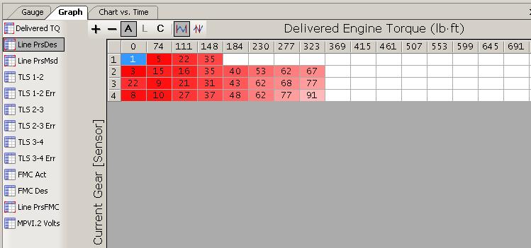
Still gingerly driving this thing and tuning the FMC/PCS to get the pressures into acceptable ranges at part throttle conditions. Thus far I have reduced the FMC in the 100-400 ft/lb range by 10-15% (which is really increasing the mA - but whatever).
Found these PCS figures to use as a reference mostly interested in the 5.7L and 6.0L applications:
The target pressures I was given by the builder were:
Park: 60-80 psi
Idle in Gear: 80-90psi
Cruise (~2000rpm): 110-120psi
Load: 160psi
So programming upwards of 227psi is acceptable by GM, right?
What I am seeing is in that range just at a very low throttle position - this is definitely correlated between the calculated torque and absolute load. To be fair this is an overdriven Procharged LS2 with a wastegate so boost comes on quickly (and therefore torque); and being that it is consistently -20 to -30*C right now is probably giving the MAF/IAT fits (arctic air density bitches!).
When compared to the pressure commanded by the FMC it makes one wonder what those figures represent. My best postulations are the PCS augments the base mechanical line pressure at various load points, in various states (static/gear/coast) by "adding" the programmed pressure number (goes from 0-148psi in HP Tuners) to the base mechanical line pressure.
So if you were to subtract the Commanded Pressure from the Measured Pressure you would likely have your Base Mechanical Pressure. Keep in mind the figures presented above are the averages of whole 10 minute drive - not the minimums vs maximums seen (which I do have access too).
I am going to plot the pressure against road speed and rpm, and then filter it for low-TPS or the like.
**2001 to 2008 valve bodies are functionally the same. A generalization but applies to this discussion.
The only difference in the spacer plate is a extra Actuator Feed Limit slot to feed the EPC Solenoid. I have mixed & matched the 2 style spacer plates with each other....Not a functional difference that I have detected!
**2007 Plate Detail (Includes M33 Hybrid) Doesn't show the extra AFL hole.
2009 Plate detail...Shows the extra AFL hole.
2004 GM Corvette replacement spacer plate....Has the extra hole (yellow)
Hello mate my problem is that bought a new plate with EP hole (yellow) hole is it okay to install it or i have to buy the other type of plate with out EP hole?


 11-07-2017, 07:40 PM