When you click on links to various merchants on this site and make a purchase, this can result in this site earning a commission. Affiliate programs and affiliations include, but are not limited to, the eBay Partner Network.
I don't know anything about a 4L60E but since rebuild suggestions are being listed in this thread just wanted to check with the experts on which upgrades/mods are necessary on a 700 rwhp build? Say 3800 lbs and and not spinning past 7000.
And yes, I probably should review the ASTG manual and more performance rebuild threads on this site and other sites before even asking these questions.
Getting ahead of myself here just out of pure curiosity alone to learn more about a performance 4L60E. Kind of embarrassing for me that I know more about the 4L80E swap into an fbody than a 4L60E when the 4L60E comes in the car lol...
Where would one start to look for a write up on the "pump mods" and "free mods" done to the 4L60E and the typical hydraulic repair parts?
I've come across mention of the items below. Which ones are done on a 700 rwhp build?
Front and Rear HD 5 Pinion Planetaries - saw mention of these in a rebuild kit
Heavy Duty Sun Shell 77749-02K
29 Element Heavy Duty Dual Cage Sprag
Using an 8 count BW High Energy frictions in the 3-4 clutch
Using a 13 vane billet pump rotor
Sonnax billet forward clutch piston
Heavy Duty Overrun Clutch Hub 74574-HD
HD input shaft
HD output shaft
Heavy Duty Reaction Shaft Kit 74602-01Kft
4th Gear Super Hold Dual Servo Kit 77767K
Making notches in the pump surface to prevent movement - where can I find pictures on this modification?
Eliminating the the partial lockup function - how is this done?
Modifying the front and rear sun gear - lube slots I'm assuming?
I've shared alot of build lists, if you put together 3 or 4 different threads you'll find much of the info I'm willing to share...but for the power you've mentioned, it's gonna take alot of attention to detail. Alot of specifics that aren't particularly easy to outline on a forum.
Your list is short and starts off at the top with a major flaw...so go find some of those other threads and then start your own to discuss
After further research, I don't think I will be installing an HD 2-3 valve. This car will be driven in "OD" all the time.
Thank you for the advice, though
No problem. I know you have been around and know what you are doing. Just throwing out some ideas you may not have thought of.
I dont see any pump mods? - The only pump mod that I had PLANNED was something I heard Maroon Monster mention awhile back: Stick a 5/16" bolt inside the pump slide spring to do the same job as a Sonnax spring.
Is there anything that you (or anyone else) recommend, while it's out? They're both 13-vane pumps, and I'm not upgrading to a 10-vane rotor. - 13v is fine, especially in your application. Honestly, unless someone has an objection, just reuse the stock spring. Your not going to be spinning this thing very high. There was a suggestion for the hardened rings. Which is a good upgrade, but again your not going to be running higher pressure and/or RPMs. But I would vacuum check the stator half for sure. PR valve usually has a lot of wear......
Are you doing the HD 2-3 valve? - Will I really gain that much with the HD 2-3 valve? This is just a stock-ish rebuild, for a totally stock 4.8. If it's going to prolong the life of the transmission and improve shift quality, I'll do it. - For your application, you can avoid this. Its just extra support for the sprag but if its just a daily this is something you dont need.
Forward and Rev Abuse valves - I was just going to use the stock ones if they vacuum-check well; is there a better option? - If they vac check ok, you will still be ok. The Sonnax abuse valves are designed different to help tighten up leaks. Specially the rev abuse valve as its connected to 3rd accumulation oil.
Forward sprag? - Both sprags from both transmissions passed the ol' "spin test," so I was planning on reusing the best of them. Unless I shouldn't - I would for sure upgrade to the Borg HD sprag. Even though im sure your orifice sizing will be conservative considering your build its just a good upgrade. I would really inspect the clutch hub where it attaches to the sprag race. Sometimes these are bent and/or cracked. Also, where the factory sprag brass rings ride. They tend to really gouge the clutch hub. Regarding the races, some say scotchbrite. Which will work in your application. Just look for chatter marks, gouges ect.
Yes, the endplay number were before the teardown. The "start" and "finish" labels referred to the start of the test (with the dial indicator at zero), and "finish" was with the shaft extended all the way. This thing isn't close to being finished yet. I'm still inspecting parts to see which are best, if either of the two are. - Cool. Regarding the inputshaft end play, I would def tighten that up with a different selective washer.
See highlighted
At the end of the day, to build a nice 4L60E you dont have to pile a bunch of name brand parts in it to make it nice unit. If you concentrate on building a tight VB and pump, you will have a nice unit for a daily. Just be careful mix and matching parts from other units. That can get a guy in trouble if your not paying attention there.....
Okay folks, I got the input shaft pressed out today. I'll be pressing it back in tomorrow.
I used a fitting from a ball-joint press kit to do this.
Here's how it fits, in case anyone is confused:
Next, it has to be placed in the opposite direction in the press; I hope this picture can explain it better than my words can. Be sure that ALL of the weight of the drum is on the steel spacer, NOT the aluminum:
Once it's located in the press, I used a 19mm impact socket to press the shaft out.
I don't think the surface is too chowdered-up; I'm going to wipe it out with some fine sandpaper tomorrow, then press the shaft back in with some red Loctite.
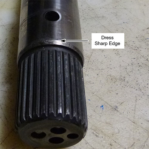
That could be hit or miss if it seals or not. I think anyway.... Also use green, not red loctite. Make sure to dress the ledge on the input shaft before you press it back in. Let dry over night and make sure to pressure test it when the drum is warm.
I don't think the surface is too chowdered-up; I'm going to wipe it out with some fine sandpaper tomorrow, then press the shaft back in with some red Loctite.
Hey look! someone else uses this phrase hahaha
Green loctite shaft retaining compound
apply liberally then blow out the feed holes, make sure they don't get plugged up
Also, the shaft has a double wide spline tooth...make sure it fits the double wide slot in the drum.
With a hydraulic press, it is not too difficult to press it in with the wrong orientation, then everything will be messed up and you'll have endless problems.
Is this something that must be done even if the drum is okay? I mean, to prevent future leaks?
You do this on all of your builds?
That could be hit or miss if it seals or not. I think anyway.... Also use green, not red loctite. Make sure to dress the ledge on the input shaft before you press it back in. Let dry over night and make sure to pressure test it when the drum is warm.
What did you mean by "dress the ledge"? It already had a bevel on it, and it cleaned up pretty well with the wire wheel.
After applying a lot of green Loctite, it pressed in a lot easier than I thought it would.
Does this look good to you?
This look like it's in far enough? At this point, the press just stopped; I gave it a couple of half-pumps to make sure it was seated, and it didn't budge.
Air check on the holes seemed good.
UPDATE: I'm going to buy all (well, MOST) of the parts I need tomorrow, but I've got a couple of questions:
1) It seems that I have two different reaction shafts (part #666 in the ATSG manual); one has a step on it, one doesn't.
Is one better than the other? The ATSG manual doesn't mention anything about this.
2) The overrun clutch hub looks pretty "chowered up"; is this still usable, or do I need a new one? (This was the best out of the two.)
The reaction shaft with the step in it takes a large Torrington bearing instead of a washer. More support. But, both those reaction shafts are worn out.
And yes, that clutch hub is worn out. As I mentioned above the stock sprag with the brass ends is what does this. Install the Borg HD sprag with steel ends.
The reaction shaft with the step in it takes a large Torrington bearing instead of a washer. More support. But, both those reaction shafts are worn out.
Can you point out exactly where they're worn? If you're talking about that area where the bushing rides, you can't even catch your fingernail on that, and I'm sure it would buff right out.
Can you point out exactly where they're worn? If you're talking about that area where the bushing rides, you can't even catch your fingernail on that, and I'm sure it would buff right out.
I'll be getting the new sprag as well.
Look at the teeth where it splines to the ring gear. You will see notches in the teeth. This is a commonly over looked part that 9.5/10 always see wear.
Look at the teeth where it splines to the ring gear. You will see notches in the teeth. This is a commonly over looked part that 9.5/10 always see wear.
How much does that really amount to, though? Those gear teeth look pretty robust.
Things like this can sometimes be hard to see in photos.
the overrun clutch hub is obvious. That belongs in the trash
but the reaction shafts....the one on the left looks to have more visible witness marks but if the full tooth profile is still there, I don't see an issue running it.
The one on the right hardly has witness marks.
Say the tooth should be 2mm wide (for easy numbers)
If that tooth is worn and you can see it has a "ledge" worn into it so not that tooth is only 1.9mm wide...that indicates it needs to be tossed.
But if the full form of the spline is in tact, and it just has slight discoloration, that doesn't necessarily mean it is bad.
I know I haven't posted anything on this thread in a while; I've been slowly working on it in my spare time (which isn't much!).
I replaced that bad reaction shaft and overrun hub, all the bushings have been installed, clutch packs checked, and my vacuum test rig is almost finished .
The valve body is the next goal.
Anyway, I've got a couple of questions: Since this build might as well be called "Project Leakstopper," I was thinking about leakage between the halves of the pump.
1) Since the pump halves don't use a gasket, a little bit of leakage is inevitable. But what if I sealed the halves with anaerobic sealant? I've been using that stuff on engine oil pumps for years with no problems.
2) I checked the input drum for leaks after reinstalling the input shaft; no leaks, even after heating it with a torch! But this got me to thinking:
Should I remove the stator support and seal it, as well? Is there anything to be gained?
If the pump's machined surfaces are flat, there should be no need for anything--torqueing to specs should be enough. The only time I've seen anything between machined surfaces was Richard at Precision puts a light coating of RTV only around the passages that go to the case vent; I think anything between 2 machined surfaces should be a no-no, but he swears by it, saying it prevents fluid from coming out the vent tube.
As for the stator tube, if there is no reason to remove it, then I wouldn't, as long as the bushings are good or you replaced them. To install it requires getting it in a specific location so internal holes line up properly, and I've read heating one part, cooling/freezing the other part--do you see where I'm going here? Unless you are installing another out of need, I wouldn't attempt it if it's not necessary.


 02-22-2022, 07:29 AM


 hahaha