
2004 - 2007 CTS-V E-Force Build Thread
 12-27-2012, 06:54 PM
#1
TECH Fanatic
Thread Starter
All right, it's been a while in the making but I have finally gotten everything installed. For reference, my vehicle is a 2004 CTS-V, with a factory replacement LS6 (motor was replaced before I purchased under warranty). The only modifications prior top installing the E-Force are .650" valve springs, LS7 lifters, and hardened push rod's.
First off, I want to thank Mark for all of his assistance here behind the scenes...his suggestions made things MUCH easier! Thanks man!
https://ls1tech.com/forums/cadillac-...questions.html
This is the thread where I procured the majority of the items for the installation:
https://ls1tech.com/forums/cadillac-...y-today-2.html
The reservoir/expansion tank did not work as I had planned, and am waiting on another one to complete the build.
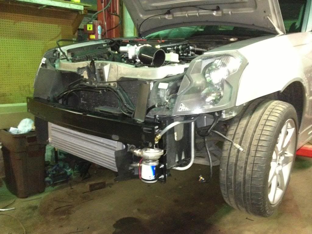
The first thing I had to do was mount the front mounted HEX and pump, the pump being much larger than I had anticipated...so much that I had to get creative with the placement.
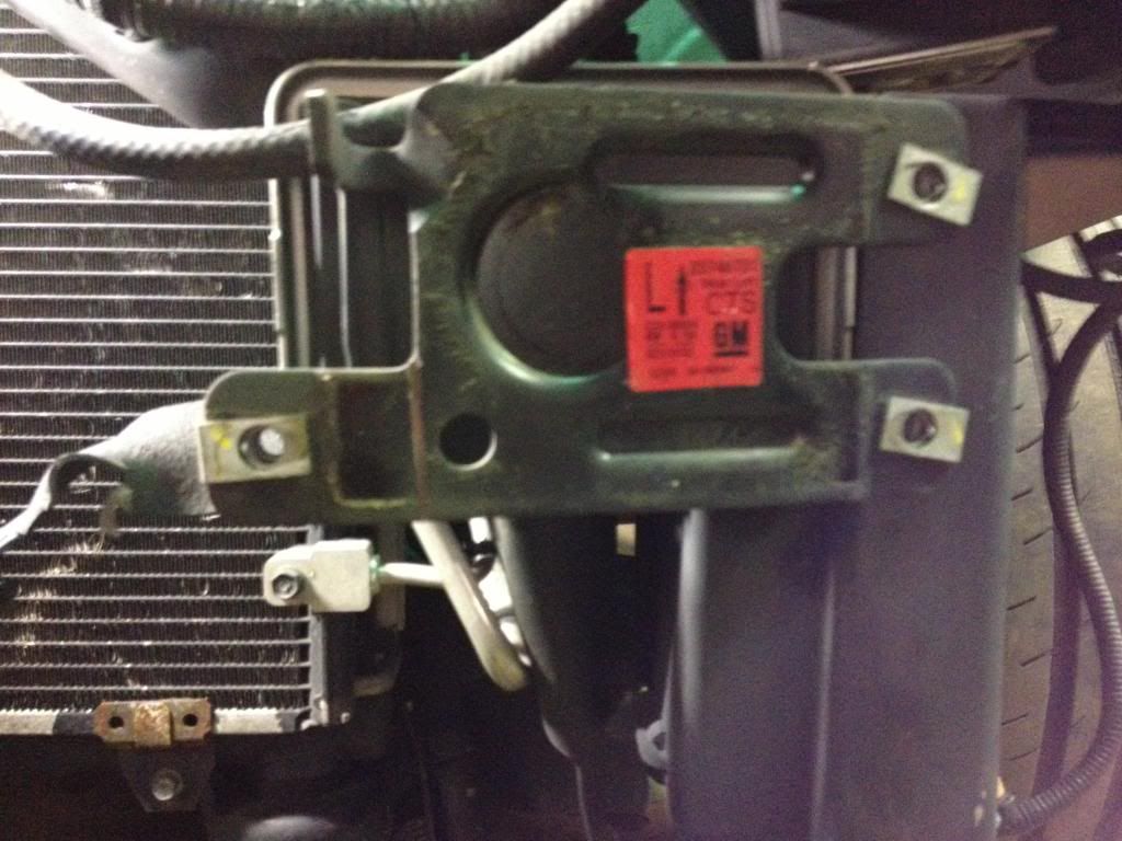
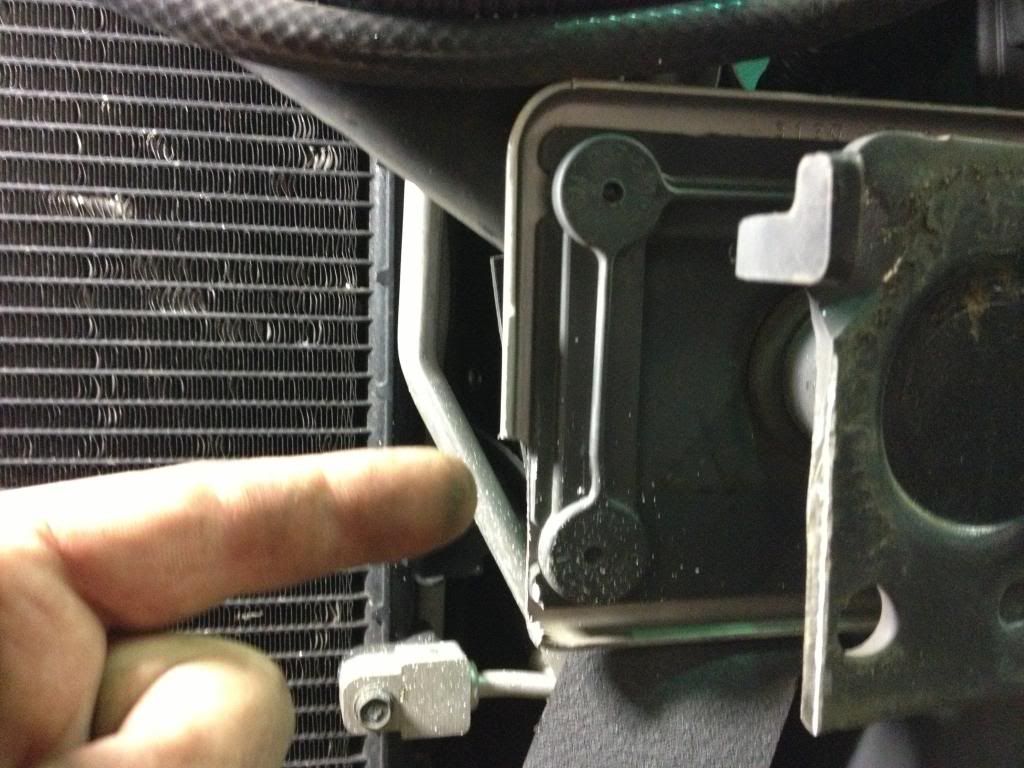
With the bumper cover and crash bar removed, I had to remove the inside tabs and captured nuts:
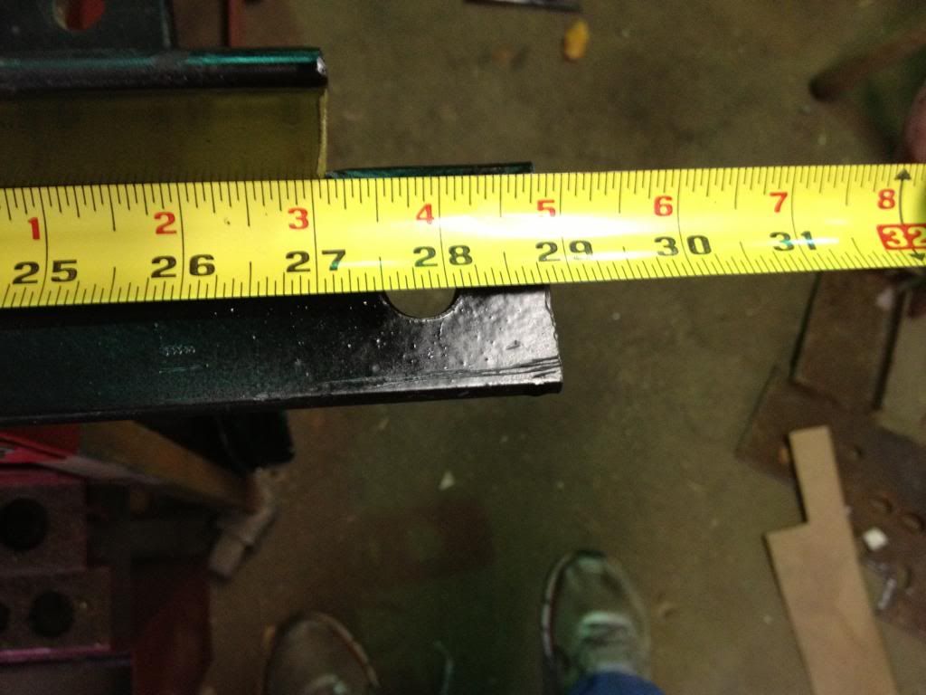
I cut a piece of steel "L" channel to span the lower retaining bolts, with two holes drilled to hang the HEX from:
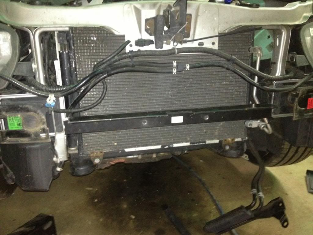


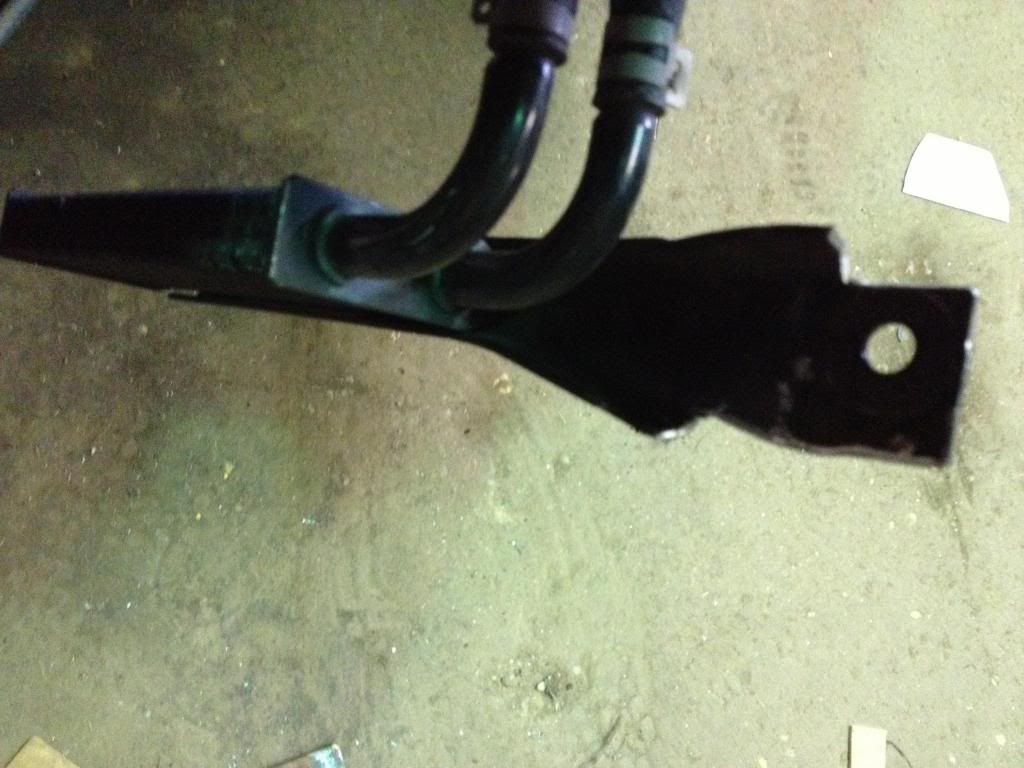
The P/S cooler bracket was trimmed and relocated to the top stud. The hoses reach without being extended, they just have to be loosened and readjusted.
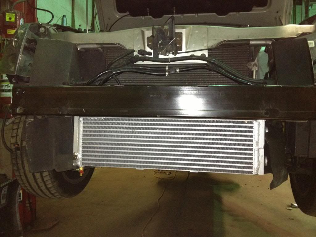
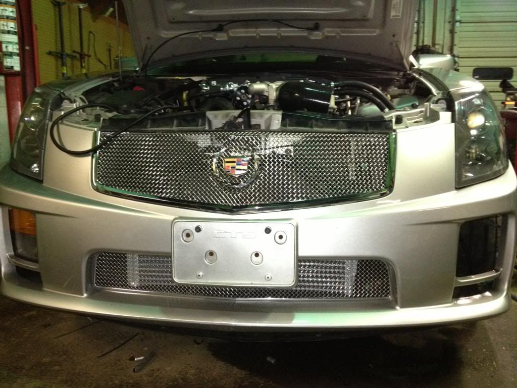
This HEX seems as if it made to the exact dimensions of our lower grille opening, it fits as if it was designed for this exact purpose!
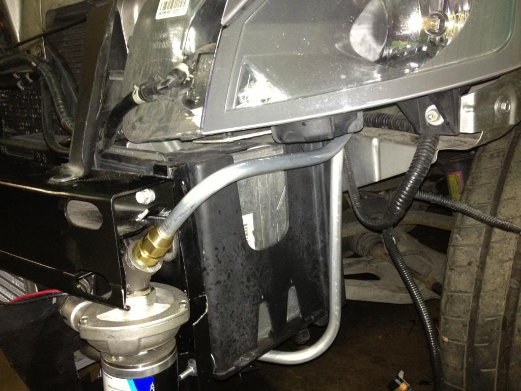
The HEX pump was pretty big, and required a bit of thinking to find a place for it. I found that there was just barely enough room for it immediately behind the bumper cover, immediately to the inside of the fog lamp. I cut some sheet metal (sourced from a rolling filing cabinet lid, haha) and removed the PCM box. I put the trimmed metal over the studs, replaced the PCM box and tightened it down...which formed the bracket that I needed to the PCM box!
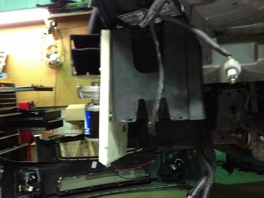

I had to fab some lower supports for the HEX...I used "X" braces from a set of old utility shelves that never made it to the scrap man. You can see the P/S cooler and horns in the second pic...the horn bracket had to be flattened straight and was attached to the top HEX retaining bolt.
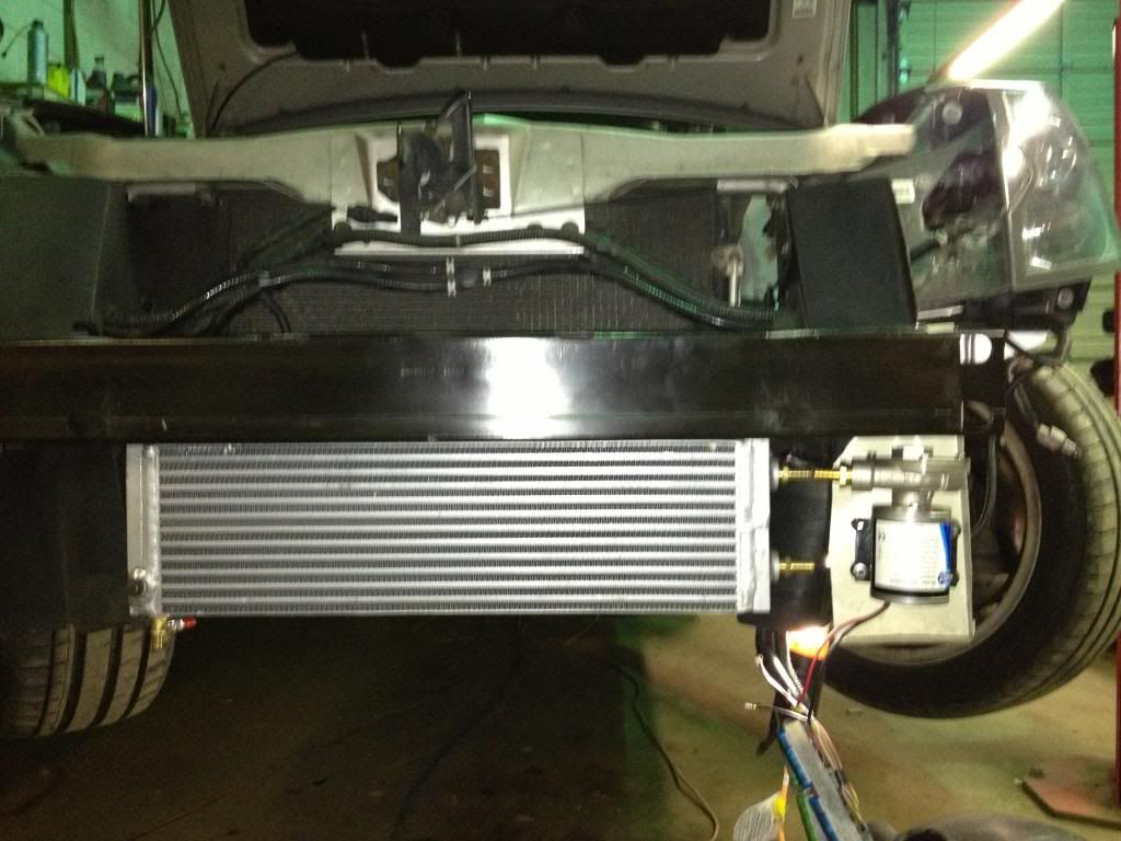
HEX and pump were plumbed together using steel fittings...street 45* fittings and a closed nipple. I had to separate the motor from the pump housing, assemble the HEX and pump rotor housing using the steel fittings, and then reinstall the motor after the HEX was bolted to the car. PITA...but it worked!
How'd it fit? Like a condom...but it's in there! Hahaha!
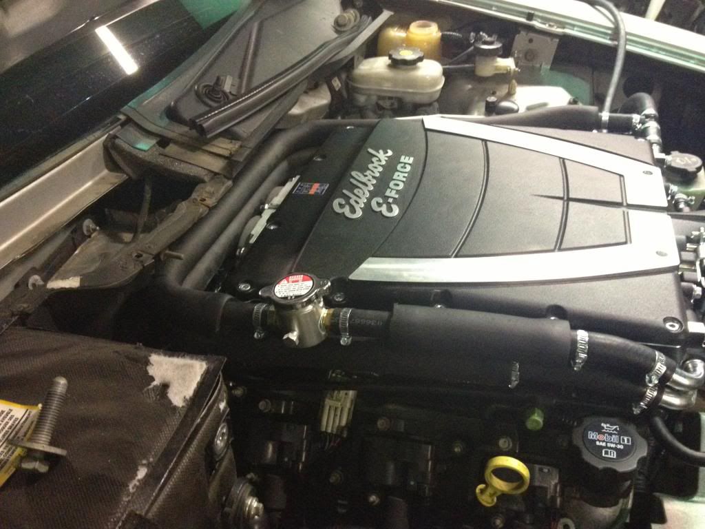
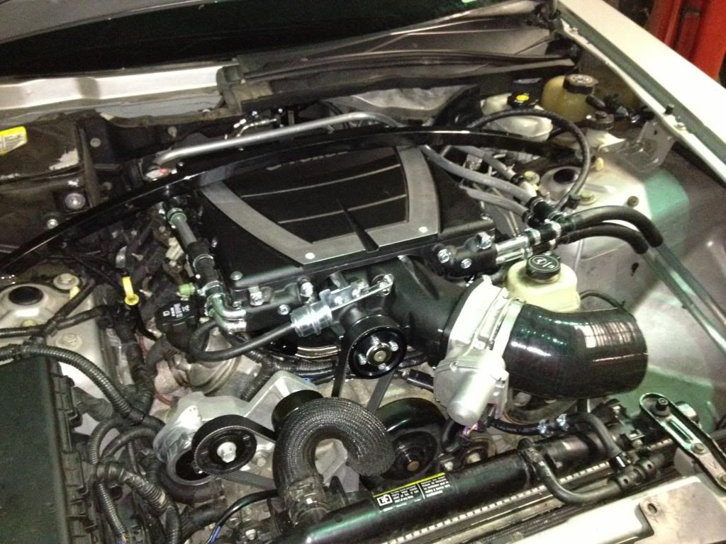
There were a few things that I wanted to change, and a few things that I had to change while I was installing the E-Force. I had an old coolant crossover vent from another LS motor (can't remember which one) and I removed the rear plugs and installed this vent. There are quite a few who advocate installing this second steam vent as they feel that it contributes to the #7 and #8 pistons/cylinder problems. It makes sense, if steam cannot get vented from the rear of the motor, it WILL cause hot spots and further damage.
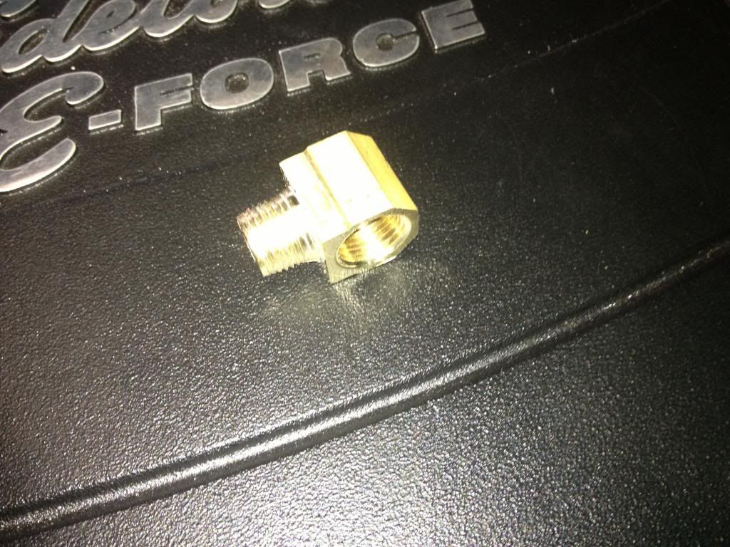
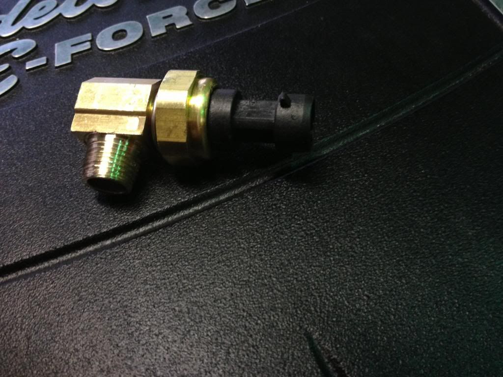
Also, since I have and LS6, I broke the oil sender as there is not enough of a relief in the E-Force runner. I got a brass 3/8" street 90* from Home Depot...and it didn't fit the block. The brass fitting was 3/8" NPT, and the block is standard thread. I got a 5/8" tap and die and cut new threads on the brass 90* to fit the block. The oil sender fit fine, as it seals using the gasket.
The rear crossover and oil sender:
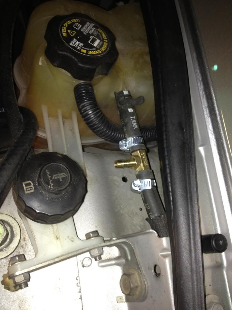
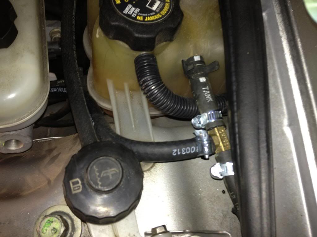
Plumbed into the surge tank line:
Oil sender:
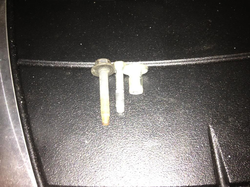
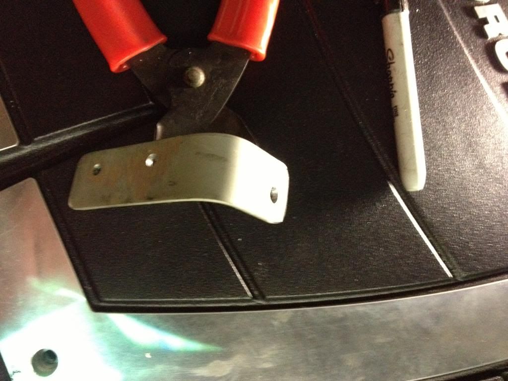
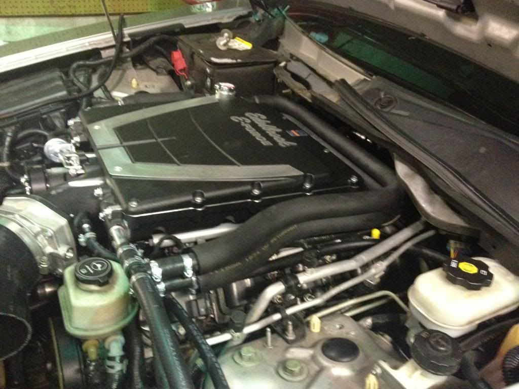
For the fuel fittings, I followed Mark's lead and used his specified parts. Only difference, I removed the center hold down bolt for the wiper module, found a longer bolt, and reinstalled the longer bolt into the sleeve. I then made a bracket (out of the same "X" bracing as the lower HEX brackets) and mounted the "Y" block since this was where the factory nylon fuel feed line naturally wound up.
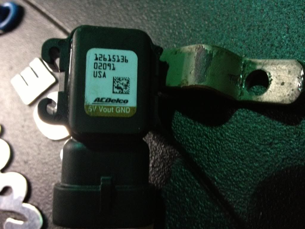
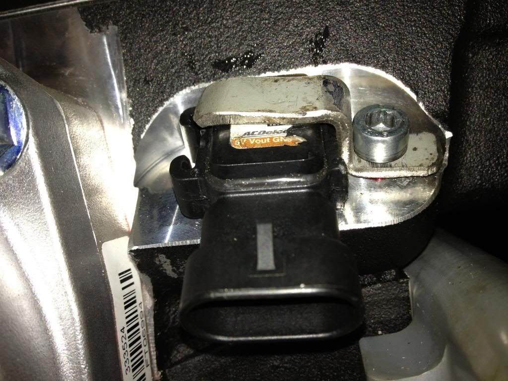
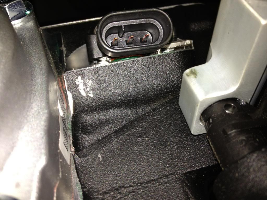
I decided not to use the supplied Ford/Bosch TMAP unit. I am running a HP Tuners 2 BAR OS so I got the Cobalt 2 BAR MAP sensor. It doesn't have to be scaled (unlike the TMAP), and cost me less than the Ford TMAP connector. I made a hold down from the same "X" bracing (can you tell how glad I am that I never throw ANYTHING away? hahah) to keep the GM 2 BAR MAP sensor in place.
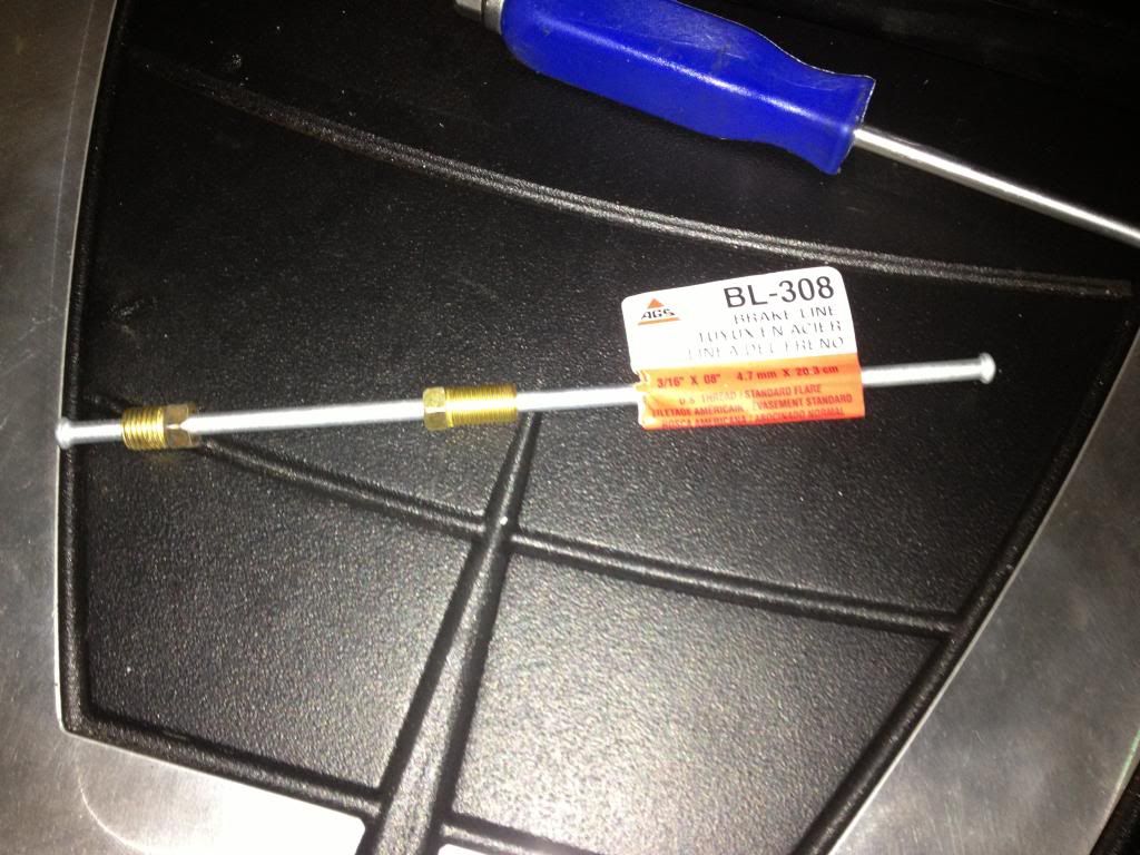
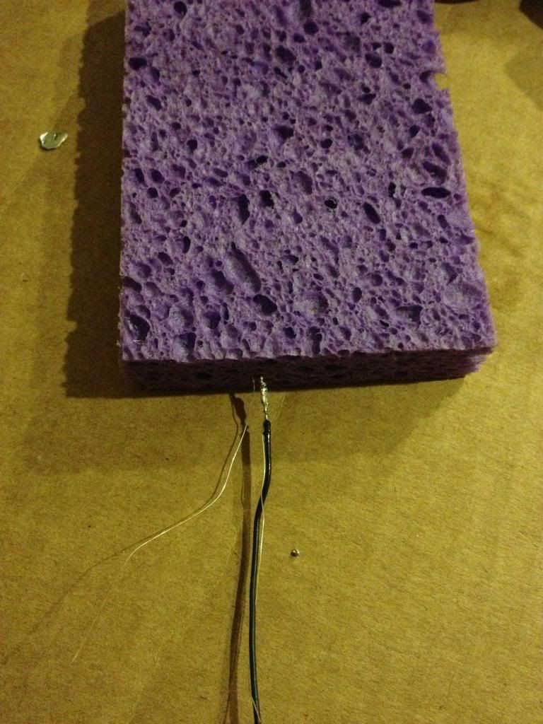
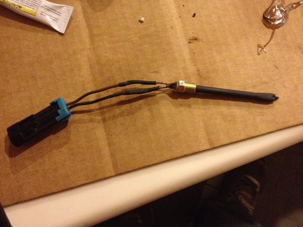
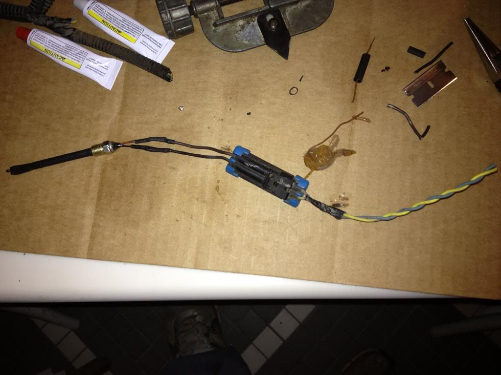
Since I did not use the TMAP, I needed another IAT sensor. I used the 1/8" boost gauge tap for this. This places the IAT immediately after the intercooler, directly in the air stream unlike the Edelbrock TMAP design. I had a few Omega thermistors on hand from when I installed one in my old Maggie...so I got a short length of 3/16" steel brake line and trimmed it down. I soldered the thermistor to 20 gauge wire, heat wrapped it, and ran it through the 3/16" brake line. On the external side of the home made IAT, I epoxied the tube closed and soldered a 2 wire connector (sourced from and old ABS circuit). Note that when you solder the thermistor, you have to keep it from getting overheated....hence the sponge. LOL!
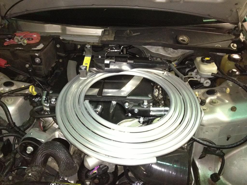
After the E-Force was installed, I changed the intercooler fittings so that the 90* fittings were both on the passenger side, and both straight fittings were on the drivers side. I used 5/8" aluminum fuel line and a ratchet bender to get the 90* radius around the E-Force. I used the "FrozenBoost.com" remote inline filler in the (top) return line...which puts it at the highest point in order to bleed the air from the system. The expansion tank I had in mind did not work out, so I have another one on order.
I wrapped all of the aluminum tubing in 3/8"x5/8" Armaflex insulation.
I have much more to add but have run out of time for the moment...MUCH MORE TO COME SOON!
First off, I want to thank Mark for all of his assistance here behind the scenes...his suggestions made things MUCH easier! Thanks man!
https://ls1tech.com/forums/cadillac-...questions.html
This is the thread where I procured the majority of the items for the installation:
https://ls1tech.com/forums/cadillac-...y-today-2.html
The reservoir/expansion tank did not work as I had planned, and am waiting on another one to complete the build.
The first thing I had to do was mount the front mounted HEX and pump, the pump being much larger than I had anticipated...so much that I had to get creative with the placement.
With the bumper cover and crash bar removed, I had to remove the inside tabs and captured nuts:
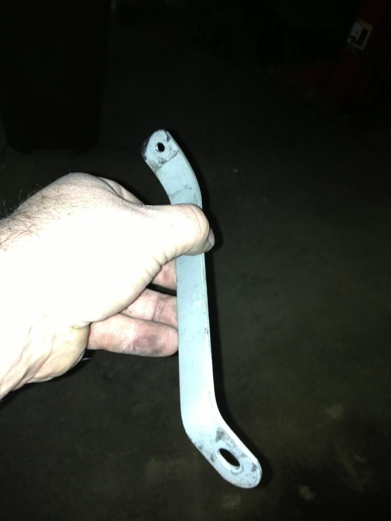
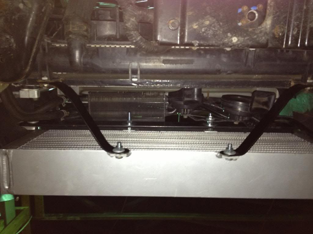
I cut a piece of steel "L" channel to span the lower retaining bolts, with two holes drilled to hang the HEX from:
The P/S cooler bracket was trimmed and relocated to the top stud. The hoses reach without being extended, they just have to be loosened and readjusted.
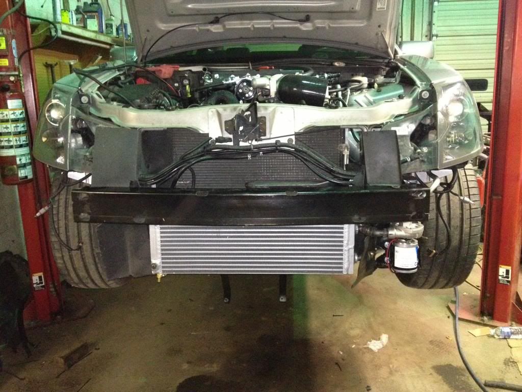
This HEX seems as if it made to the exact dimensions of our lower grille opening, it fits as if it was designed for this exact purpose!
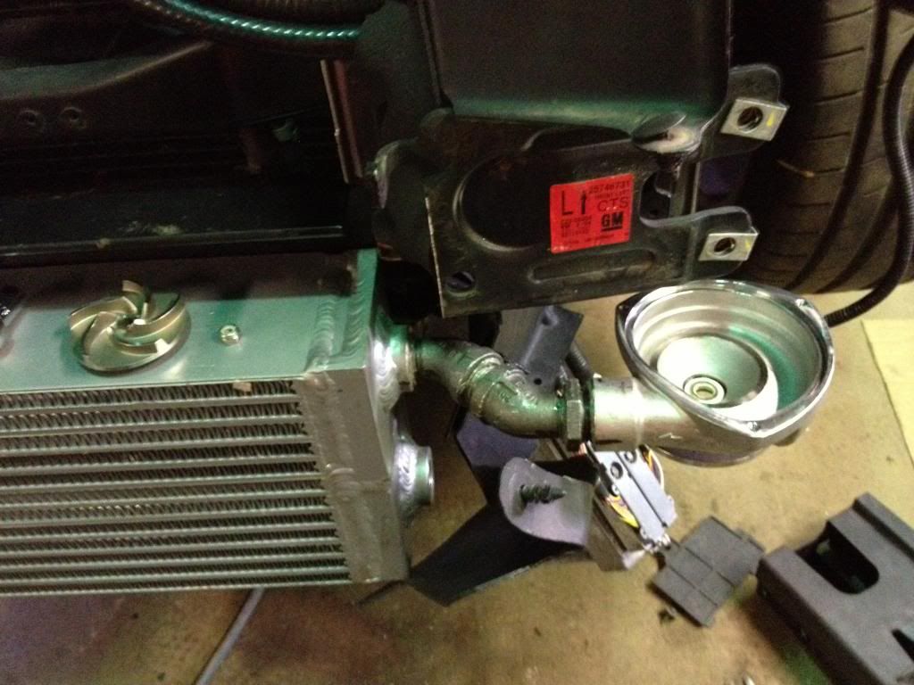
The HEX pump was pretty big, and required a bit of thinking to find a place for it. I found that there was just barely enough room for it immediately behind the bumper cover, immediately to the inside of the fog lamp. I cut some sheet metal (sourced from a rolling filing cabinet lid, haha) and removed the PCM box. I put the trimmed metal over the studs, replaced the PCM box and tightened it down...which formed the bracket that I needed to the PCM box!
I had to fab some lower supports for the HEX...I used "X" braces from a set of old utility shelves that never made it to the scrap man. You can see the P/S cooler and horns in the second pic...the horn bracket had to be flattened straight and was attached to the top HEX retaining bolt.
HEX and pump were plumbed together using steel fittings...street 45* fittings and a closed nipple. I had to separate the motor from the pump housing, assemble the HEX and pump rotor housing using the steel fittings, and then reinstall the motor after the HEX was bolted to the car. PITA...but it worked!
How'd it fit? Like a condom...but it's in there! Hahaha!
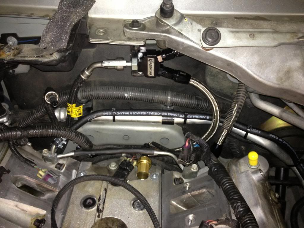
There were a few things that I wanted to change, and a few things that I had to change while I was installing the E-Force. I had an old coolant crossover vent from another LS motor (can't remember which one) and I removed the rear plugs and installed this vent. There are quite a few who advocate installing this second steam vent as they feel that it contributes to the #7 and #8 pistons/cylinder problems. It makes sense, if steam cannot get vented from the rear of the motor, it WILL cause hot spots and further damage.
Also, since I have and LS6, I broke the oil sender as there is not enough of a relief in the E-Force runner. I got a brass 3/8" street 90* from Home Depot...and it didn't fit the block. The brass fitting was 3/8" NPT, and the block is standard thread. I got a 5/8" tap and die and cut new threads on the brass 90* to fit the block. The oil sender fit fine, as it seals using the gasket.
The rear crossover and oil sender:
Plumbed into the surge tank line:
Oil sender:
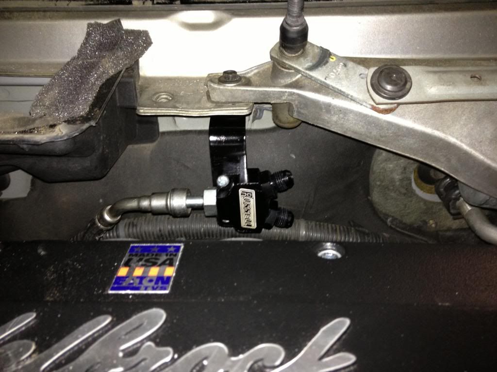
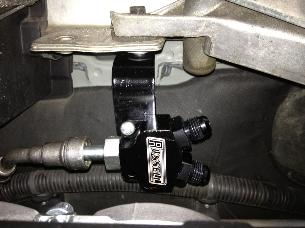
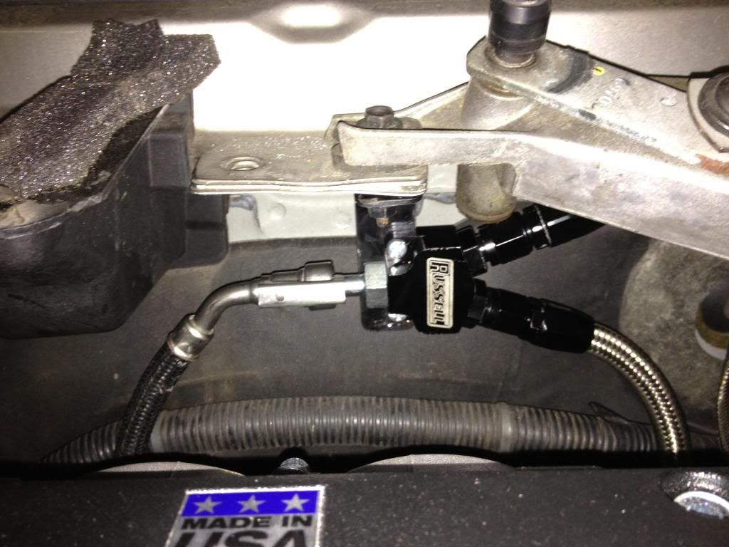
For the fuel fittings, I followed Mark's lead and used his specified parts. Only difference, I removed the center hold down bolt for the wiper module, found a longer bolt, and reinstalled the longer bolt into the sleeve. I then made a bracket (out of the same "X" bracing as the lower HEX brackets) and mounted the "Y" block since this was where the factory nylon fuel feed line naturally wound up.
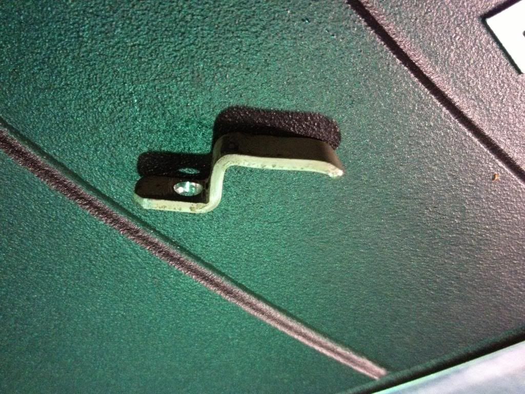
I decided not to use the supplied Ford/Bosch TMAP unit. I am running a HP Tuners 2 BAR OS so I got the Cobalt 2 BAR MAP sensor. It doesn't have to be scaled (unlike the TMAP), and cost me less than the Ford TMAP connector. I made a hold down from the same "X" bracing (can you tell how glad I am that I never throw ANYTHING away? hahah) to keep the GM 2 BAR MAP sensor in place.
Since I did not use the TMAP, I needed another IAT sensor. I used the 1/8" boost gauge tap for this. This places the IAT immediately after the intercooler, directly in the air stream unlike the Edelbrock TMAP design. I had a few Omega thermistors on hand from when I installed one in my old Maggie...so I got a short length of 3/16" steel brake line and trimmed it down. I soldered the thermistor to 20 gauge wire, heat wrapped it, and ran it through the 3/16" brake line. On the external side of the home made IAT, I epoxied the tube closed and soldered a 2 wire connector (sourced from and old ABS circuit). Note that when you solder the thermistor, you have to keep it from getting overheated....hence the sponge. LOL!
After the E-Force was installed, I changed the intercooler fittings so that the 90* fittings were both on the passenger side, and both straight fittings were on the drivers side. I used 5/8" aluminum fuel line and a ratchet bender to get the 90* radius around the E-Force. I used the "FrozenBoost.com" remote inline filler in the (top) return line...which puts it at the highest point in order to bleed the air from the system. The expansion tank I had in mind did not work out, so I have another one on order.
I wrapped all of the aluminum tubing in 3/8"x5/8" Armaflex insulation.
I have much more to add but have run out of time for the moment...MUCH MORE TO COME SOON!
Last edited by DMM; 12-28-2012 at 05:55 PM.


 12-28-2012, 08:47 AM
#6
TECH Apprentice
iTrader: (2)
Join Date: Nov 2007
Location: fairfax, VA
Posts: 321
Likes: 0
Received 0 Likes
on
0 Posts

very nice! looking forward to more pics, drive vids, dyno #'s and kill stories.
so since you've got it all figured out, I should just buy everything and drop my car off at your place and it'll be good to go the following weekend? haha
so since you've got it all figured out, I should just buy everything and drop my car off at your place and it'll be good to go the following weekend? haha
Trending Topics
12-28-2012, 11:21 AM
#8
On The Tree

Join Date: Jan 2006
Posts: 114
Likes: 0
Received 0 Likes
on
0 Posts
 12-28-2012, 01:13 PM
#10
TECH Fanatic
Thread Starter
For the filter, I have temporarily stubbed the 4" K&N filter immediately behind the drivers side head light in much the same was as any CAI does, only without the shield. I intend to pipe the air filter into the well behind the fog lamp. I wanted to get this thing on the road!
Oh, BTW - this damn thing SCREAMS! It's as noisy during regular driving as the Maggie was at full throttle!
Yes! A bit...have a few pics to post about that. Only sections of the under hood bracing need to be trimmed away for clearance, the exterior remains unharmed.
Thanks for the props everyone! Hope to have the thread almost finished this evening!
12-28-2012, 01:28 PM
#11
Sensing for what? If you mean to inquire about the MAF sensor, I don't need it as I have a custom 2 BAR Speed Density OS in the PCM. The 2 BAR MAP sensor is all that is needed.
For the filter, I have temporarily stubbed the 4" K&N filter immediately behind the drivers side head light in much the same was as any CAI does, only without the shield. I intend to pipe the air filter into the well behind the fog lamp. I wanted to get this thing on the road!
Oh, BTW - this damn thing SCREAMS! It's as noisy during regular driving as the Maggie was at full throttle!
I'm curious about the 2 BAR OS upgrade, but despite reading "about" it, I have no idea what a 1, 2, and 3 BAR OS does.
With the TVS2300 wailing away, I bet you don't hear your valvetrain at all!
12-28-2012, 01:53 PM
#12
TECH Fanatic
Thread Starter
Have you seen this tuning school?
I'm curious about the 2 BAR OS upgrade, but despite reading "about" it, I have no idea what a 1, 2, and 3 BAR OS does.
With the TVS2300 wailing away, I bet you don't hear your valvetrain at all!
I'm curious about the 2 BAR OS upgrade, but despite reading "about" it, I have no idea what a 1, 2, and 3 BAR OS does.
With the TVS2300 wailing away, I bet you don't hear your valvetrain at all!
A two BAR system reads the one atmosphere (up to zero PSI) and an additional atmosphere above that (+14.7 PSI of boost). Hence, a 2 BAR system is effective to 14.7 PSI of boost (although you could scale the system if you wanted/needed to go a little higher).
The one drawback (which isn't much) is that you loose resolution of the sensor, not by much though...I honestly don't think 5 KPa makes a huge difference anyhow. The Stock MAP sensor reads 15, 20, 25. 30, etc...the 2 BAR reads 30, 40, 50, 60, etc.
There are those that say SD will cause drivability problems b/c it cannot directly measure the incoming combustion air in the same manner as the MAF sensor, which is actually correct. If you drive from point "A" to point "B" and the barometric pressure changes drastically from when you first started the engine, you could notice something. However, there is a simple fix for this...if you happen to drive straight up Mt. Everest and you felt as if you were having a drivability concern...pull over, turn the car off, and turn it back on. Once you cycle the ignition, the MAP acts as a BARO and the calibration starts from there. Used to happen quite often way back in the day with the early GM SD TBI motors.
Mark said that his E Force had almost reached the limits of his LS3 MAF and that he was likely going to try SD as well. He has a stock cubed LS3 motor with an E Force, so I decided to jump straight to the 2 BAR.
Last edited by DMM; 12-28-2012 at 09:04 PM. Reason: Clarification
12-28-2012, 02:28 PM
#13
THANK you. Finally, it clicks.
I'm surprised that you haven't considered something like the VMP 115mm suck-through MAF, rather than go through all of that trouble with the 2 bar OS upgrade.

http://vmptuning.com/index.php?p=product&id=1299
Any downsides that occur to you? I assume that airspeed past the sensor at idle would be incredibly low, but couldn't you do SD up to a certain engine RPM and then revert to the MAF?
I'm surprised that you haven't considered something like the VMP 115mm suck-through MAF, rather than go through all of that trouble with the 2 bar OS upgrade.
http://vmptuning.com/index.php?p=product&id=1299
Any downsides that occur to you? I assume that airspeed past the sensor at idle would be incredibly low, but couldn't you do SD up to a certain engine RPM and then revert to the MAF?
12-28-2012, 02:54 PM
#14
TECH Fanatic
Thread Starter
THANK you. Finally, it clicks.
I'm surprised that you haven't considered something like the VMP 115mm suck-through MAF, rather than go through all of that trouble with the 2 bar OS upgrade.
http://vmptuning.com/index.php?p=product&id=1299
Any downsides that occur to you? I assume that airspeed past the sensor at idle would be incredibly low, but couldn't you do SD up to a certain engine RPM and then revert to the MAF?
I prefer the MAP OS anyhow, it reacts much faster to changes (which is why GM uses the "blended" system; MAP for quick transitions, MAF for steady state) and I feel that it is more accurate **when the IAT sensor provides ACCURATE readings** to base calculations from.
12-28-2012, 03:28 PM
#15
TECH Apprentice
iTrader: (2)
Join Date: Nov 2007
Location: fairfax, VA
Posts: 321
Likes: 0
Received 0 Likes
on
0 Posts
are you running a boost, fuel pressure, wideband or any combination of the 3? what boost levels are you currently seeing? how is the tuning going with it?
can you get some idle/driving vids?
ps. update your sig haha
can you get some idle/driving vids?
ps. update your sig haha
12-28-2012, 04:14 PM
#16
TECH Fanatic
Thread Starter
I am measuring boost through the logging software, and it looks as if i'm going to need a bigger pulley. I have the 3.25" pulley which should be good for approximately 10 PSI of boost...which I have confirmed, only I have 10 PSI of boost at 2800 RPM...which is too much for a stock block IMO. I have approximately 6 PSI of boost at 1600 RPM, which is what I believe is causing my problems at the moment.
Farthest I have taken it so far is to about 4k, and I think that was wheel spin. The RevShift bushings work well to mitigate wheel hop, BTW

I'll get some video's this weekend, my daughter took the GoPro so I'll have to get it back from her.
 12-28-2012, 06:15 PM
#18

Also, as I have mentioned before,
going to a 2 or 3 Bar OS upgrade, you then get BE tables. You cant see Boost with a MAF, but you can with a BARO sensor.
You can then enrich your fueling based on boost pressure, rather than RPM.
There are tricks when using the MAF and the Hz, and that would be to slow the air velocity, meaning, a larger tube, more air, slower velocity and under the 12 KHz.
Another incredibly tedious trick is to re-scale what the ECM sees as air flow (through the injector values) (Only for the advanced calibrators!) Meaning, you can scale the ecm down 1/3... but have to 1/3 all values in ANY table which uses air - Ive done it once, i think there were a few dozen tables that required very careful re-scaling
An example of why we want to do re-scaling is hitting the ECM ROM value limit of 511.99g/sec as DMM mentioned
Nice progress DMM!
Last edited by vmapper; 12-28-2012 at 06:24 PM.
 12-28-2012, 06:29 PM
#20
1. Idle is very difficult unless you maintain the SD/MAF blend..
2. you dont 'see' boost
3. These ECM have a limit 511g/sec, which if you plan to run 700+rwhp, will give you problems.
Large MAF tubes have too low of even airflow for measurement. Its a pita to tune idle and low rpm.
I had to install a honeycomb to straighten the airflow to reduce the "jumping around" the MAF sensor was giving during idle, which helped considerably... add in a big cam... good luck.
In the end, I prefer SD over MAF always.
And I used a LS7 slot Sensor. (has IAT built in)