What did you do to your V today?
 09-26-2016, 02:52 PM
#901
TECH Addict
iTrader: (19)
Join Date: Aug 2007
Location: Where the Navy tells me to go
Posts: 2,403
Received 106 Likes
on
88 Posts

Check the wiring harness and connectors. I don't know why, but they seem very finicky on my car. I've unplugged the harness and found corrosion on the pins in the past; it was bad enough that I cut a couple new connectors off a car at the junkyard so I could splice them in. Last week I was foolish enough to reposition the driver side harness and zip-tie it out of the way, which caused the driver side turn signal/DRL to stop working.  Had to pull the wheel well liner back out, unplug all the connectors, make sure they were clean, plug 'em back in, didn't actually change anything, and miraculously the bulb was back to working fine.
 09-26-2016, 03:38 PM
#902
all the wiring looked good in there, its always been a desert car so corrosion is usually not a problem  the bulb popped half of it was black. got lucky and bought a wrong set a few years back and threw them in the bulb bin. they always get used eventually........... next time i take the front off for some reason i want to load some led bulbs in there. slowly converting them all over.
the bulb popped half of it was black. got lucky and bought a wrong set a few years back and threw them in the bulb bin. they always get used eventually........... next time i take the front off for some reason i want to load some led bulbs in there. slowly converting them all over.
09-27-2016, 03:33 PM
#903
Staging Lane

Finished up my clutch job about a week ago, almost through the 150 break in miles. Project was originally just a slave cyl job, but fk it as long as I'm in there, right?
Parts replaced - Slave cylinder, Clutch, Flywheel, rear main, driveshaft bearing.
Went with the LS9X clutch kit, had problems initially bc the captured disc wasn't aligned (later finding out this has been a recent issue, likely assembly machine out of tolerance I guess), so had to put the PP in a hydraulic press to relieve the pressure on the disc and center it. Sent the driveshaft to Voodoo Chicken for rebuilding. Used a Fel-Pro rear main first bc dealer wasn't open, ended up buying the OE part anyways due to the poor fitment of the Fel-Pro. I'd highly advise anyone replacing their rear main to just get the OE seal and not chance a sketchy aftermarket part.
Results - Love the LS9 clutch, feels very similar to stock with a more competent pedal feel, zero noise/chatter. 2-piece flywheel is brilliant, engine revs fast as **** now making rev match easier. Driveshaft is tight, no more clunk on throttle lift. Overall drive train feels like a brand new car, extremely happy.
Also pumped all my control arm bushings up with the Prothane Super Grease finally, that stuff is awesome!
Next project is going to be piecing together an external oil cooler setup. Got put off by my slave failing so now I can save up for that if everything else stays healthy.
10-02-2016, 06:59 PM
#905
TECH Addict
iTrader: (19)
Join Date: Aug 2007
Location: Where the Navy tells me to go
Posts: 2,403
Received 106 Likes
on
88 Posts
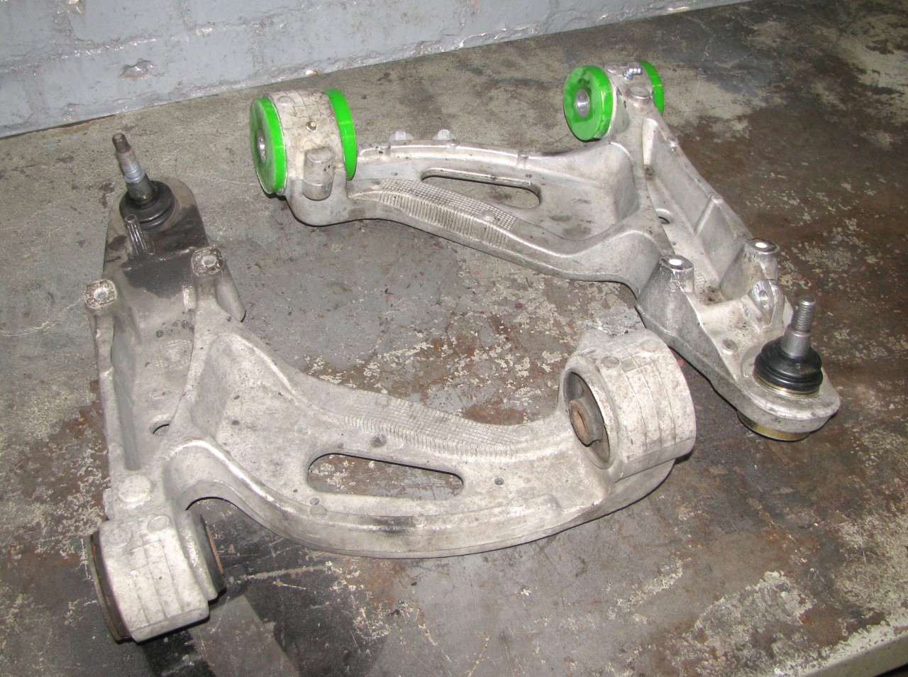
Swapped out the front control arms with some junkyard spares. I scavenged the arms earlier this year, and then bought some green Revshift bushings in the classifieds here. Had a shop remove the old bushings, as I didn't want to fight with those, and install new ball joints. I then drilled all the bushings for grease zerks, something I've found to be very handy with poly bushing installs on my Subaru - did those way back in 2007, and have a grease gun loaded with a tube of bushing grease from Energy Suspension or Prothane. Never had any noise issues, thanks to the occasional greasing.
A few pics from the last month or so as I gradually worked on the zerks and bushings:
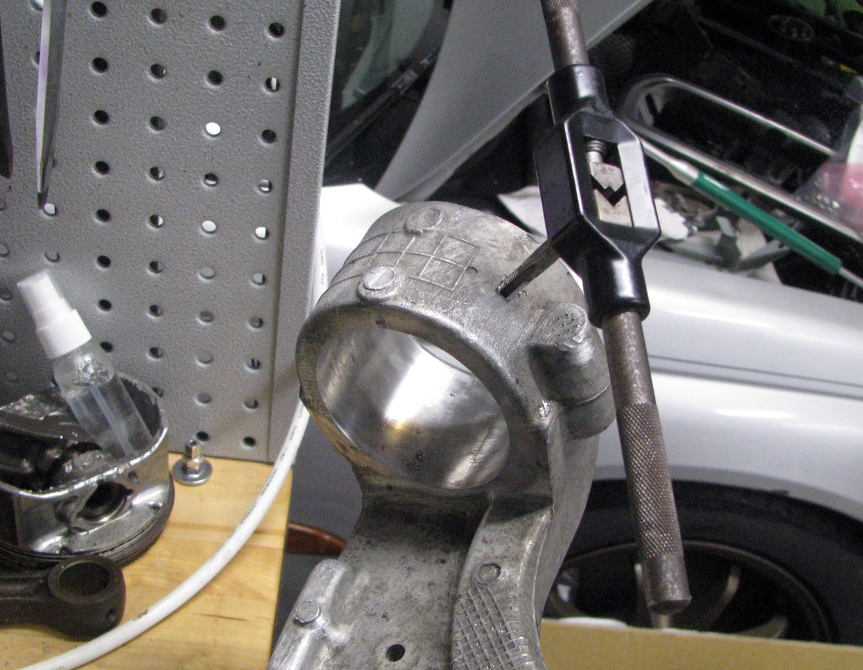
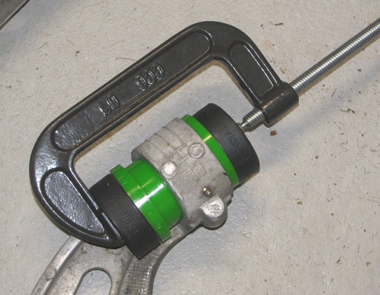
[Note that hockey pucks make excellent floor jack pads, and also come in handy for cramming bushings in with a C-clamp.]
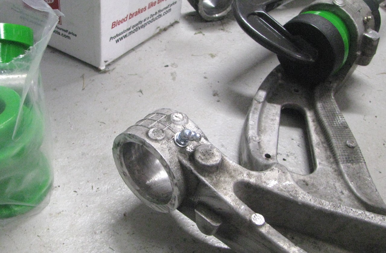
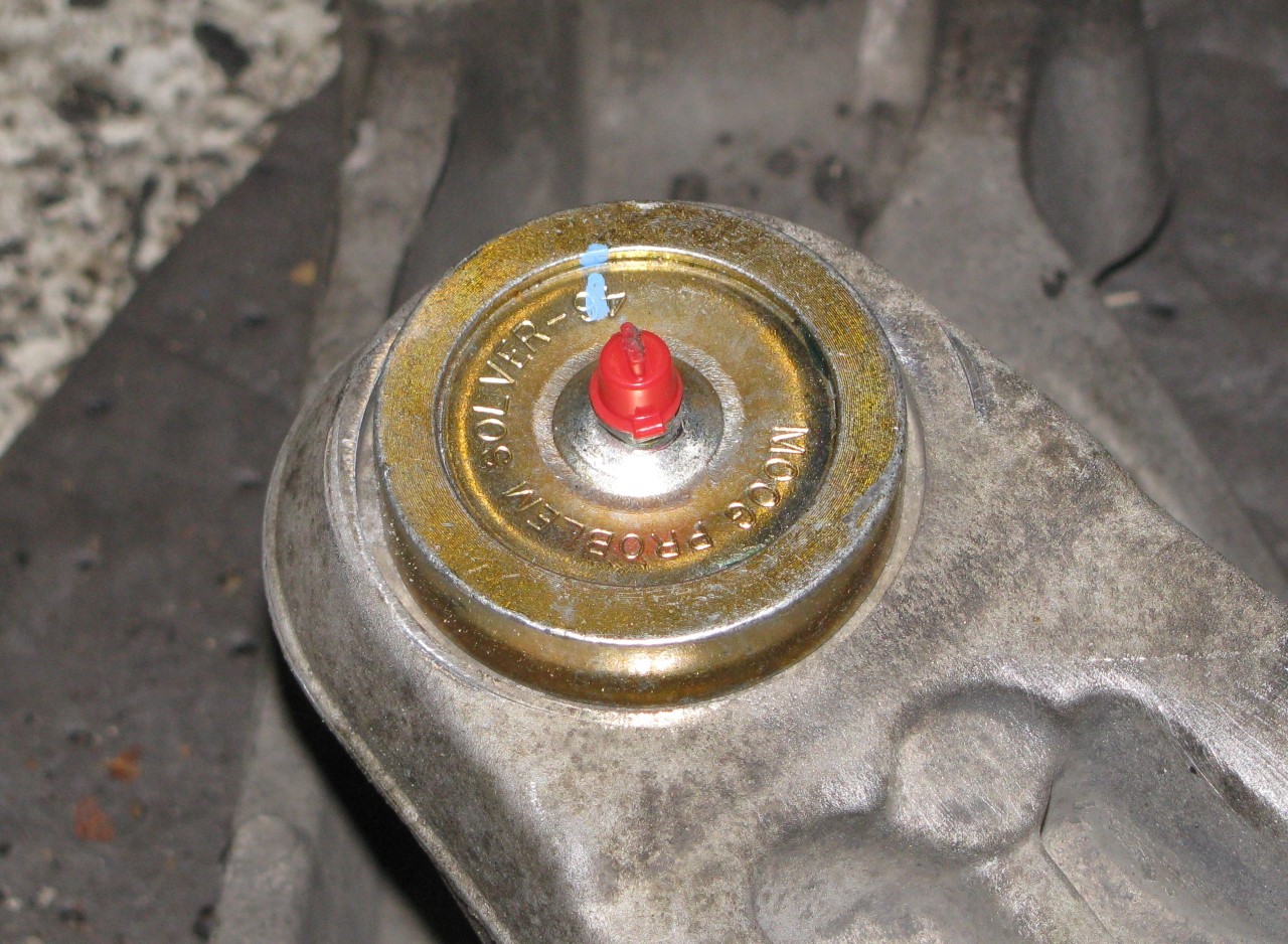
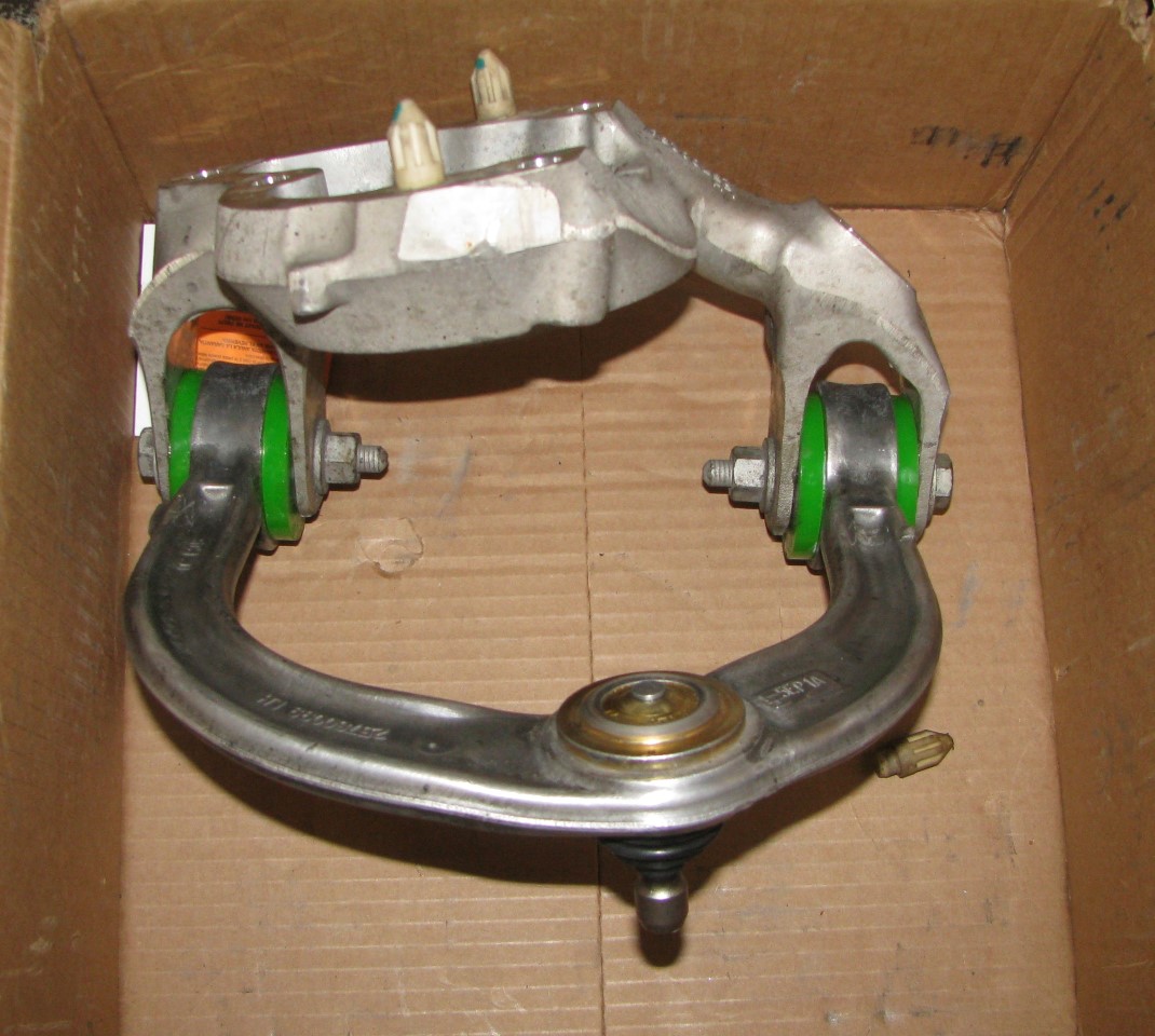
"New" driver side arm next to the old one during the swap today:
You can see that based on the shape of the bushing housing area, I used 1 45* zerk and 1 straight zerk to get them pointed in the right direction. Upper arm has straight zerks on the bottom of the arms, again angled about 45 deg to ease access with the grease gun. Not shown is that, after installing the bushings, and before installing the zerks for the final time, I drilled a channel through the bushing. The zerks are pretty much lined up with the split between the bushing halves, but I wanted to ensure there was a good flow path for grease to get from the zerk to the bushings sleeves. (Years ago, when I did the bushing install on the Subaru, I found some zerks that had an extended threaded portion, so they would thread through the control arm and actually into the bushing. Looked all over to find more of those with no luck. I'm sure the normal, short zerks will be just fine.)
Only had 1 lonely grease zerk cap left over from the batch of 25 that I bought probably 8 or 10 years ago. More on order.
Also took the opportunity to swap out the upper control arm mounts. Passenger side I didn't really need to do, but the driver side has a bolt hole that I had to heli-coil a while back, so I figured I'd take the opportunity to swap it out since I had to remove it anyway.
Found the forward mounting hole in the cradle on the driver side looked like someone had attacked it with, uh, I dunno. Something that made it look like ***.
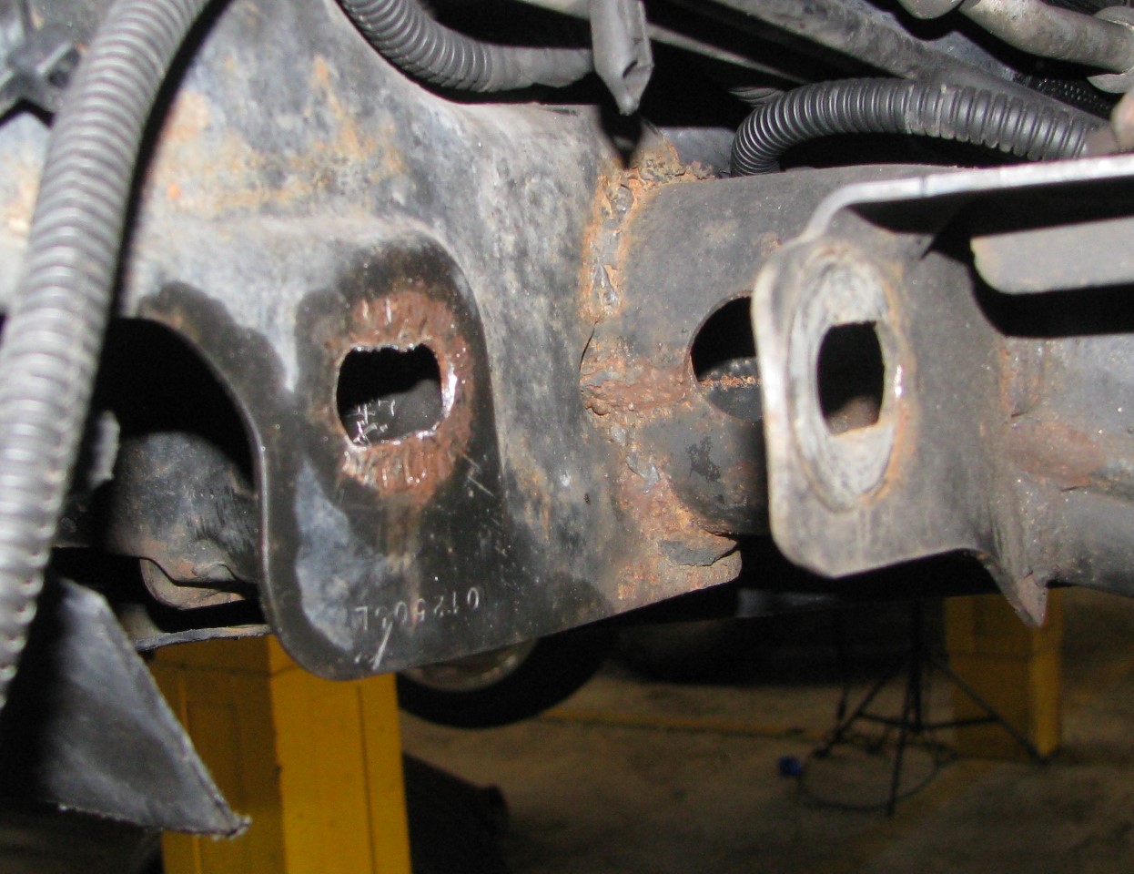
View from below, looking aft:
Of course, when I loaded the car with tools this morning I thought to myself, Nah, no need to bring the Dremel. Would've come in handy. Instead, I cleaned things up a bit with a round file and called it good.
Also forgot that I need to drill out the sway bar end link mounting ears to 12mm, since I'm using Vette links. Doh! So, for now the front sway bar is disconnected, with the end links in a box. I'll get those reinstalled in the coming days.
Alignment is AFU now, not surprisingly, steering wheel off about 30deg to the left. Appointment on Wednesday morning to get that taken care of.
A few pics from the last month or so as I gradually worked on the zerks and bushings:
[Note that hockey pucks make excellent floor jack pads, and also come in handy for cramming bushings in with a C-clamp.]
"New" driver side arm next to the old one during the swap today:
You can see that based on the shape of the bushing housing area, I used 1 45* zerk and 1 straight zerk to get them pointed in the right direction. Upper arm has straight zerks on the bottom of the arms, again angled about 45 deg to ease access with the grease gun. Not shown is that, after installing the bushings, and before installing the zerks for the final time, I drilled a channel through the bushing. The zerks are pretty much lined up with the split between the bushing halves, but I wanted to ensure there was a good flow path for grease to get from the zerk to the bushings sleeves. (Years ago, when I did the bushing install on the Subaru, I found some zerks that had an extended threaded portion, so they would thread through the control arm and actually into the bushing. Looked all over to find more of those with no luck. I'm sure the normal, short zerks will be just fine.)
Only had 1 lonely grease zerk cap left over from the batch of 25 that I bought probably 8 or 10 years ago. More on order.
Also took the opportunity to swap out the upper control arm mounts. Passenger side I didn't really need to do, but the driver side has a bolt hole that I had to heli-coil a while back, so I figured I'd take the opportunity to swap it out since I had to remove it anyway.
Found the forward mounting hole in the cradle on the driver side looked like someone had attacked it with, uh, I dunno. Something that made it look like ***.
View from below, looking aft:
Of course, when I loaded the car with tools this morning I thought to myself, Nah, no need to bring the Dremel.
Would've come in handy. Instead, I cleaned things up a bit with a round file and called it good.Also forgot that I need to drill out the sway bar end link mounting ears to 12mm, since I'm using Vette links. Doh!
So, for now the front sway bar is disconnected, with the end links in a box. I'll get those reinstalled in the coming days.Alignment is AFU now, not surprisingly, steering wheel off about 30deg to the left. Appointment on Wednesday morning to get that taken care of.
Last edited by AAIIIC; 10-02-2016 at 07:04 PM.
10-02-2016, 08:19 PM
#906
TECH Enthusiast
Swapped out the front control arms with some junkyard spares. I scavenged the arms earlier this year, and then bought some green Revshift bushings in the classifieds here. Had a shop remove the old bushings, as I didn't want to fight with those, and install new ball joints. I then drilled all the bushings for grease zerks, something I've found to be very handy with poly bushing installs on my Subaru - did those way back in 2007, and have a grease gun loaded with a tube of bushing grease from Energy Suspension or Prothane. Never had any noise issues, thanks to the occasional greasing.
A few pics from the last month or so as I gradually worked on the zerks and bushings:
[Note that hockey pucks make excellent floor jack pads, and also come in handy for cramming bushings in with a C-clamp.]
"New" driver side arm next to the old one during the swap today:
You can see that based on the shape of the bushing housing area, I used 1 45* zerk and 1 straight zerk to get them pointed in the right direction. Upper arm has straight zerks on the bottom of the arms, again angled about 45 deg to ease access with the grease gun. Not shown is that, after installing the bushings, and before installing the zerks for the final time, I drilled a channel through the bushing. The zerks are pretty much lined up with the split between the bushing halves, but I wanted to ensure there was a good flow path for grease to get from the zerk to the bushings sleeves. (Years ago, when I did the bushing install on the Subaru, I found some zerks that had an extended threaded portion, so they would thread through the control arm and actually into the bushing. Looked all over to find more of those with no luck. I'm sure the normal, short zerks will be just fine.)
Only had 1 lonely grease zerk cap left over from the batch of 25 that I bought probably 8 or 10 years ago. More on order.
Also took the opportunity to swap out the upper control arm mounts. Passenger side I didn't really need to do, but the driver side has a bolt hole that I had to heli-coil a while back, so I figured I'd take the opportunity to swap it out since I had to remove it anyway.
Found the forward mounting hole in the cradle on the driver side looked like someone had attacked it with, uh, I dunno. Something that made it look like ***.
View from below, looking aft:
Of course, when I loaded the car with tools this morning I thought to myself, Nah, no need to bring the Dremel. Would've come in handy. Instead, I cleaned things up a bit with a round file and called it good.
Also forgot that I need to drill out the sway bar end link mounting ears to 12mm, since I'm using Vette links. Doh! So, for now the front sway bar is disconnected, with the end links in a box. I'll get those reinstalled in the coming days.
Alignment is AFU now, not surprisingly, steering wheel off about 30deg to the left. Appointment on Wednesday morning to get that taken care of.
A few pics from the last month or so as I gradually worked on the zerks and bushings:
[Note that hockey pucks make excellent floor jack pads, and also come in handy for cramming bushings in with a C-clamp.]
"New" driver side arm next to the old one during the swap today:
You can see that based on the shape of the bushing housing area, I used 1 45* zerk and 1 straight zerk to get them pointed in the right direction. Upper arm has straight zerks on the bottom of the arms, again angled about 45 deg to ease access with the grease gun. Not shown is that, after installing the bushings, and before installing the zerks for the final time, I drilled a channel through the bushing. The zerks are pretty much lined up with the split between the bushing halves, but I wanted to ensure there was a good flow path for grease to get from the zerk to the bushings sleeves. (Years ago, when I did the bushing install on the Subaru, I found some zerks that had an extended threaded portion, so they would thread through the control arm and actually into the bushing. Looked all over to find more of those with no luck. I'm sure the normal, short zerks will be just fine.)
Only had 1 lonely grease zerk cap left over from the batch of 25 that I bought probably 8 or 10 years ago. More on order.
Also took the opportunity to swap out the upper control arm mounts. Passenger side I didn't really need to do, but the driver side has a bolt hole that I had to heli-coil a while back, so I figured I'd take the opportunity to swap it out since I had to remove it anyway.
Found the forward mounting hole in the cradle on the driver side looked like someone had attacked it with, uh, I dunno. Something that made it look like ***.
View from below, looking aft:
Of course, when I loaded the car with tools this morning I thought to myself, Nah, no need to bring the Dremel.
Would've come in handy. Instead, I cleaned things up a bit with a round file and called it good.Also forgot that I need to drill out the sway bar end link mounting ears to 12mm, since I'm using Vette links. Doh!
So, for now the front sway bar is disconnected, with the end links in a box. I'll get those reinstalled in the coming days.Alignment is AFU now, not surprisingly, steering wheel off about 30deg to the left. Appointment on Wednesday morning to get that taken care of.
10-03-2016, 10:29 AM
#907
Looks like the slots were extended to allow for greater camber adjustment. I'm surprised that was needed in the front though. You can pretty much tuck the front tire and still get the camber in spec. I've only had the camber adjustment bottomed out in the rear.
10-03-2016, 07:35 PM
#911
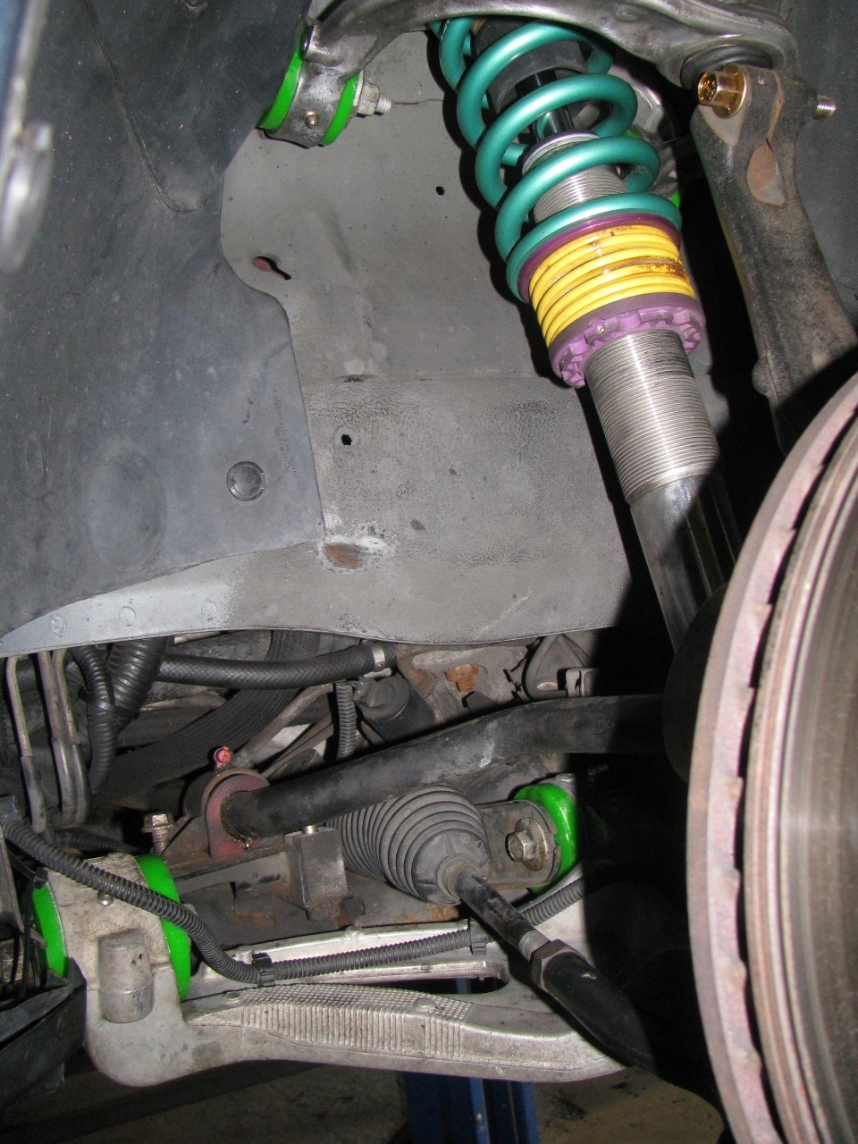
Here's an in-process shot from when I did my control arms. This is far from finished, but should give you an idea:
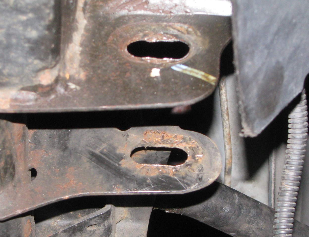
The initial cut (partially complete):

AAIIIC's worn but otherwise unmodified slots:
The initial flush cut to the "lip" on the lower part of the subframe:

Once you're done and paint over the gore, it'll look something like this:


But notice how even with the clearancing, there are practical limits to how far the arm can rotate when it's shoved all the way inboard:

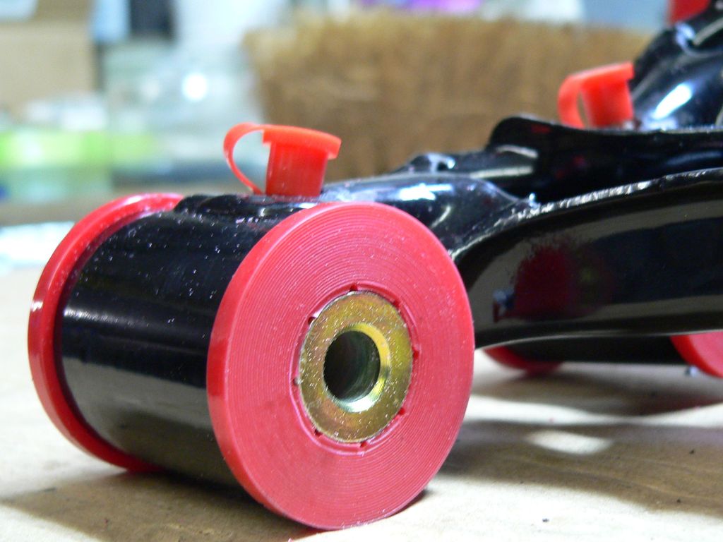
As a final note, you don't need to drill into Revshift bushings to ensure that they get lubricated by the zerks. Test it out if you don't believe me--pump a bunch of grease in there and it'll shoot out between the metal sleeve and the ID of the bushings. Revshift sets their bushings' ODs so that they're a strong interference fit into the control arms. This keeps the bushings from rotating.
The IDs are designed to provide a light interference fit to the metal sleeves after you install the bushings into the control arms. This eliminates slop and still allows a well-lubricated bushing to turn without squeaking. There's also an intentional gap between the two bushing halves. When you pump grease into the zerk, the grease finds the path of least resistance, which is between the bushing halves and between the OD of the rotating metal sleeve and the ID of the stationary polyurethane bushing.
The two complaints I have about Revshift's designs (and I've mentioned this to both John and Tony on various occasions) is that they don't polish their sleeves (reduces friction) and they don't machine grease channels in their bushings. Grease channels are great because they store more grease than smooth bushing walls can, and they collect FOD that would otherwise be ground against the metal sleeves. Here's a design with grease channels:
And here's a sleeve surface finish comparison after about 30 seconds (per sleeve) of polishing using a drill, some metal polish, and a microfiber cloth. I left a little undone so that you can see the difference:

Last edited by FuzzyLog1c; 10-03-2016 at 07:45 PM.
10-04-2016, 03:59 PM
#913

5 years, 250 working days a year and on average at least one alignment per day sometimes many more than that...Yes, I've literally aligned over a 1000 front ends and I can't remember ever seeing this phenomena. I'll check the next time I have mine apart or I'm at the junkyard but if what is, essentially, the frame of the car is getting elongated due to normal wear and tear, I'd consider it a problem.
I would certainly question why only one of the slots is "buggered" up and the other slot, which is capturing the same bolt, is otherwise perfect. This, in my mind at least, would represent some movement on one end of the bolt but not the other which doesn't make much sense unless the bolt were just ever so slightly loose.
I would certainly question why only one of the slots is "buggered" up and the other slot, which is capturing the same bolt, is otherwise perfect. This, in my mind at least, would represent some movement on one end of the bolt but not the other which doesn't make much sense unless the bolt were just ever so slightly loose.
10-04-2016, 04:10 PM
#914
You're correct, to a point. Once the sleeve gets rough enough, the raised edges outweigh the advantage of holding a more grease. As an example of "how far is too far," I still have pictures of the black pipe Creative Steel used to use as their bushing sleeves. 80% of the manufacturing cost of quality polyurethane bushings is the machining of the steel or aluminum sleeve, which is one reason why I've always been a big fan of Revshift. But I polished my sleeves and machined little grease channels into the polyurethane by hand. So I've got the best of both worlds.
Last edited by FuzzyLog1c; 10-04-2016 at 04:19 PM.
10-04-2016, 04:22 PM
#915
5 years, 250 working days a year and on average at least one alignment per day sometimes many more than that...Yes, I've literally aligned over a 1000 front ends and I can't remember ever seeing this phenomena. I'll check the next time I have mine apart or I'm at the junkyard but if what is, essentially, the frame of the car is getting elongated due to normal wear and tear, I'd consider it a problem.
I would certainly question why only one of the slots is "buggered" up and the other slot, which is capturing the same bolt, is otherwise perfect. This, in my mind at least, would represent some movement on one end of the bolt but not the other which doesn't make much sense unless the bolt were just ever so slightly loose.
I would certainly question why only one of the slots is "buggered" up and the other slot, which is capturing the same bolt, is otherwise perfect. This, in my mind at least, would represent some movement on one end of the bolt but not the other which doesn't make much sense unless the bolt were just ever so slightly loose.
The weird thing, as you mentioned, is that those irregularities are only found on the sides where the unthreaded (edit: threaded? I can't remember which way they're pointed) part of the bolt passes through. If there's enough room there for the bolt to bang up and down, maybe it's more of a "mismatched bolt/slot size" problem.
Last edited by FuzzyLog1c; 10-04-2016 at 04:35 PM.
10-05-2016, 09:25 AM
#916
I don't think the subframe mounting tabs are thick enough, given the weight and performance of the V1. The material might have been thick enough for the regular CTS, but every V1 I've seen has those wavy lines in the lower front slots.
The weird thing, as you mentioned, is that those irregularities are only found on the sides where the unthreaded (edit: threaded? I can't remember which way they're pointed) part of the bolt passes through. If there's enough room there for the bolt to bang up and down, maybe it's more of a "mismatched bolt/slot size" problem.
The weird thing, as you mentioned, is that those irregularities are only found on the sides where the unthreaded (edit: threaded? I can't remember which way they're pointed) part of the bolt passes through. If there's enough room there for the bolt to bang up and down, maybe it's more of a "mismatched bolt/slot size" problem.
A slightly undersized mounting flange flexing on the bolt threads could cause this I guess but you'd think the bolt would be damaged as well.
AAIIC, what do the bolts look like?
10-05-2016, 08:05 PM
#917
TECH Addict
iTrader: (19)
Join Date: Aug 2007
Location: Where the Navy tells me to go
Posts: 2,403
Received 106 Likes
on
88 Posts
I'm running Watkins Glen on the 14th & 15th, and I'm definitely looking forward to seeing how it feels on track.
Extended-length slots are very obvious on the V1 because they cut into the chamfered area of the mounting tabs, and the lower part of the subframe gets cut flush to allow the lower part of the control arm "barrel" to rotate with the control arm pressed inboard as far as it will go.
The bolts looked fine. On both sides it was only the forward-most hole (which corresponds to the threaded end of the forward bolt) that was a bit chewed up.
10-05-2016, 08:15 PM
#918
Staging Lane
iTrader: (1)

Join Date: Apr 2014
Location: Chicagoland
Posts: 86
Likes: 0
Received 0 Likes
on
0 Posts
Assuming, of course, I wanted to cut slots to give less negative camber, something that would never occur to me.
10-08-2016, 08:50 PM
#919
TECH Addict
iTrader: (19)
Join Date: Aug 2007
Location: Where the Navy tells me to go
Posts: 2,403
Received 106 Likes
on
88 Posts
- Drilled out the end link mounting tabs on the "new" front control arms so I could install my end links.
- Used a hydraulic press and an air chisel to knock apart an old wheel bearing / hub assembly so I have just the hub to use as a guide for drilling out new brake rotors. Didn't really need the air chisel, but it made it easy to pop things off.
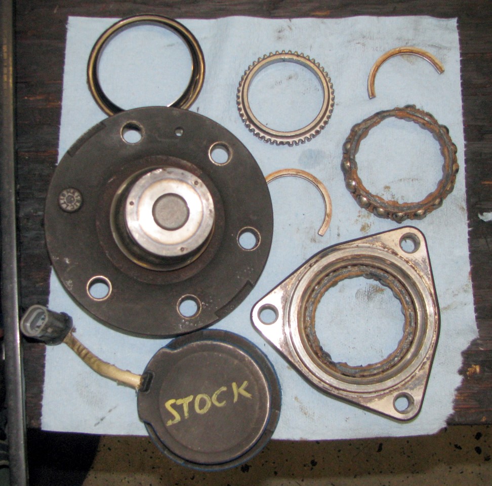
The back cover I just pried off with a screwdriver (working my way around the circumference). Once that's off you'll see the toothed ring for the ABS (top center). It's press fit onto the inner end of the hub, and was taken off with the air chisel. Next are the 2 half circle pieces that you can see at top right and in the middle - I don't know what one would call those, but they're what actually hold the hub in place inside the wheel bearing. They fit into a groove in the hub and ride on the inner race. Again, knocked those loose with the air chisel. Once those were out, the hub pressed right out. Top left is the outer dust shield, which was on the hub once the hub came out of the bearing assembly.
This particular hub assembly wore out and came off the car a number of years ago. The inner bearing still looks good - you can see the tan-colored grease on the bearing. Not shown is the outer bearing, which was toast - grease was all black.
- Used a hydraulic press and an air chisel to knock apart an old wheel bearing / hub assembly so I have just the hub to use as a guide for drilling out new brake rotors. Didn't really need the air chisel, but it made it easy to pop things off.
The back cover I just pried off with a screwdriver (working my way around the circumference). Once that's off you'll see the toothed ring for the ABS (top center). It's press fit onto the inner end of the hub, and was taken off with the air chisel. Next are the 2 half circle pieces that you can see at top right and in the middle - I don't know what one would call those, but they're what actually hold the hub in place inside the wheel bearing. They fit into a groove in the hub and ride on the inner race. Again, knocked those loose with the air chisel. Once those were out, the hub pressed right out. Top left is the outer dust shield, which was on the hub once the hub came out of the bearing assembly.
This particular hub assembly wore out and came off the car a number of years ago. The inner bearing still looks good - you can see the tan-colored grease on the bearing. Not shown is the outer bearing, which was toast - grease was all black.