When you click on links to various merchants on this site and make a purchase, this can result in this site earning a commission. Affiliate programs and affiliations include, but are not limited to, the eBay Partner Network.
Do you live in Ventura? My wife is from there! I think I've been to the Costco in the pic above, lol! Nice area!
RE: A/C- Did your car have it originally? If so, will you use the existing dash components? Or go Vintage Air or similar? If not, (same question)?
I don't live in Ventura but I'm not far away. That is the Oxnard Costco in the photo (off Rose Ave). I grew up in the area and I have lived at various times in Ventura, Oxnard, Santa Paula and Camarillo.
My car is an original factory AC car. The system was 100% intact when I first bought the car in 1998. I no longer have the original condenser, drier, and A6 compressor, but the factory "suitcase" with the evaporator and all the interior ductwork and controls are still in place. I plan to use all the factory controls and evaporator.
During the LS swap I mounted a large parallel flow Vintage Air condenser up front. The original condensers on these cars were tube and fin which is less effective or efficient. I also notched the AC suitcase for clearance while repairing a few cracks and holes with fiberglass. I replaced the high speed fan relay which appeared to have shorted. I notched my subframe to low mount a fixed displacement compressor from an '07 truck. On the interior, lubed all the cables and door pivots so the flaps operate properly to allow control of hot/cold air blended, defrost, floor, bi-level etc. The factory system uses a vacuum control valve to operate flaps in the kick panel and cowl to control fresh air vs. recirculate - the valve is one component I need take a look at and test because it's very stiff to operate. I have not yet connected it to a vacuum source.
The factory system uses a POA valve (pilot operated absolute) to regulate the evaporator pressure and therefore temperature. With a POA system, the compressor runs all the time and the POA valves regulates a bypass of refrigerant flow to keep it at the optimal pressure and prevent the evaporator from freezing up. Since the original system was calibrated for R12, the POA needs to be adjusted to get the right evaporator pressure demanded by R134a. I have not yet looked at my POA valve, but many have an adjustment screw that can be used to set the pressure. Some people buy a "POA eliminator" which replaces the pressure regulating function of the POA with a temperature-based control to cycle the compressor clutch. I would like to get the POA valve working if I can. Of course you know I will document every step when I get to that point.
Here's what I think will be involved:
(1) Clean, calibrate and install POA valve
(2) Mount drier
(3) Replace TXV
(4) Make ac lines and replace all seals
(5) Wire compressor and fans
(6) Recondition vacuum control valve
(7) Flush, oil and charge the system
I have ordered most of what I need for the above, although I will have a find a local place to crimp the AC beadlock ends. If all goes well the system will be up and running just in time for winter!
Last edited by -TheBandit-; 08-08-2018 at 04:02 PM.
It does not suck to drive the Nova every chance I can get.
Doing more night driving highlighted some wiring issues with the exterior lighting. The housing-based ground on one of the taillight sockets is very unreliable so it is frequently going out - I can get it to work again by moving the socket around, but it often just goes out again while I'm driving. I had a headlight shut off due to a corroded connector. The blinkers sometimes work, sometimes don't. Lack of reliable exterior lighting is a serous safety concern, so I am going to limit my night driving and start researching harness replacement.
I had a little problem driving home from the gym last night. I noticed at the first light I stopped at my coolant temperature was spiking. I'll admit I got a little panicked as the needle was rapidly climbing.
I pulled into the nearest parking lot and shut the car down. I am always fearful of opening the hood on a car that's overheating. Once a friend of mine popped the hood while his car was overheating and in that moment one of his hoses blew off and spouted hot coolant everywhere. Luckily he wasn't scalded.
My first thought was to check the fan fuse and sure enough it was blown.
When I originally wired the fan I decided to use a maxi fuse. I knew a smaller form factor like an ATM or ATC fuse would not survive the high startup currents of this fan, but even a maxi fuse has it's limits. I planned to use a 40a fuse, but had a 30a handy in a fuse assortment so that's what I used. It worked for the last two years, but finally gave up. In the original application for this Volvo fan the wiring incorporated a fuseable link - that would be an even better option. But for this round I waited for the car to cool down, drove to the nearest auto parts store, and popped in a new 40a fuse. The fan is working fine again. I'll be sure to carry a spare from here on.
You mentioned LED tails. Have you looked at designing a PC board? I used FreePCB to design my lights, then soldered them together as a proof-of-concept. I would like to add a digital controller to my small powder coating oven to make SMD boards, which would be thinner and less prone to breaking solder joints from stress and vibration.
The lenses are a big sticking point. I hate the additional refraction in the middle of the side markers, as well as the pillowed look in the front bumper and tails. I redesigned the side marker housings, but the added complexity of making new lenses turned me off. I would love to find a place that could mold new lenses.
Edit: Something like Fesler, but with a reverse light.
I have started researching and mocking up things for the air conditioning. I dug through some very old storage bins to find my original POA (pilot operated absolute) valve. I took this off and bagged it in a ziplock around 1999. Since then all the evaporator lines have been taped off. Here she is in all her glory.
This has got to be one of the most misunderstood devices known to cars of this era. Part of the problem with understanding this device is you also have to understand refrigeration to understand it's purpose. I'll attempt to explain it the way I understand - feel free to chime in if you have a better explanation.
The POA valve is located at the exit of the evaporator. It is a normally closed valve and it remains closed until the absolute pressure in the evaporator reaches the setpoint of the POA valve. It is possible for the evaporator pressure to go above this setpoint, but not below it. The absolute pressure is used rather than a gauge pressure so the function of the valve is not affected by altitude changes.
So why would you want the evaporator pressure to always stay above a setpoint? The answer is that the pressure dictates the boiling point temperature of the refrigerant. If the pressure goes lower, the boiling point will go lower. The POA valve is calibrated from the factory at 30psig or 308kpa absolute. At this pressure, the boiling point (aka "saturation temperature") of R12 refrigerant is - drum roll please - 0C/32F - the freezing point for water. So in short, the POA valve prevents the evaporator from going below 0C/32F and therefore prevents water from freezing on the evaporator.
Notice that the pressure setpoint of the POA valve is based on the boiling point of the refrigerant. These days R134a is the refrigerant of choice. At 30psig / 308kpa absolute, the boiling point (saturation temperature) of R134a is roughly 1.4C/34.6F. This is still safely above the freezing point of water, but increases the evaporator temperature by about 2.6deg F. Re-calibrating the POA valve can bring that back down and potentially improve AC performance. Looking at the properties of R134a, the boiling point (saturation temperature) will be 0C/32F at a pressure of 27.75psig / 292.63 kpa absolute. This should be the new setpoint for the POA valve.
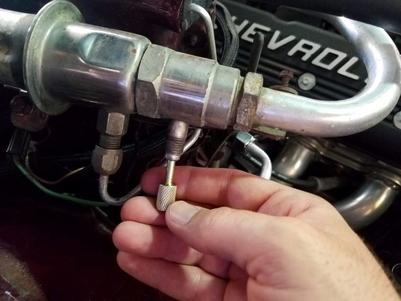
To adjust the POA setpoint, there is a locknut and adjustment screw down inside the exit of the valve (pictured below). Once I have a set of gauges I will make the adjustment and show exactly how this is done.
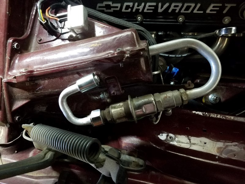
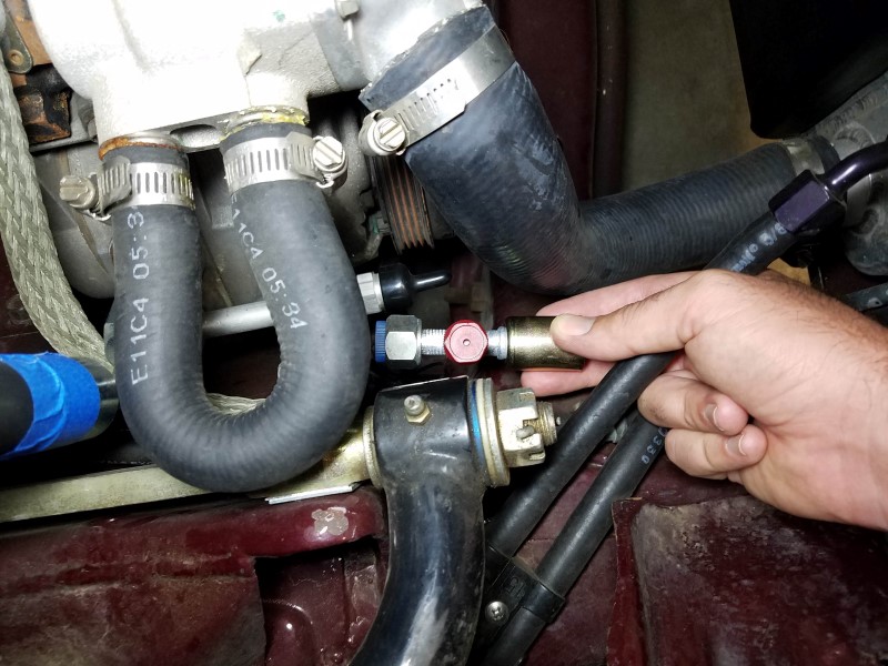
Meanwhile I have been sorting out fittings and hose ends to plumb the system. One place where a standard fitting poses a problem is at the exit of the POA valve. This joint is a #12 o-ring, however the standard size now used for the suction line to the compressor is #10. I needed a 180 degree #12 to #10 "step down" fitting which was much harder to find than I thought it would be. First I ordered one from Nostalgic Auto Air part number G135. I was hoping I could flip this fitting down so the hose would exit underneath the POA valve, but unfortunately it interfered with the hood hinge spring. So here is what it looks like aiming in the factory orientation
I didn't particularly like the aim of that fitting or how the barrier hose would be routed along the top of the evaporator. I found another option from Original Air aka Classic Auto Air part number G13-407 which mimics the original "shepard's hook" fitting, but is sized with a #10 hose outlet.
I picked up a prepackaged assortment of #6, #8 and #10 beadlock fittings and hose from ebay. #10 is used for the low pressure vapor suction line from the evaporator to the compressor. #8 is used for the high pressure vapor line from the compressor to the condenser. #6 is used for the high pressure liquid line from the condenser to the drier and back to the TXV valve on the evaporator.
Just playing around with hose routing last night it looks like the suction line especially is going to add to the ugly, cluttered mess that is the factory AC system. I can't think of a better way to route it than to just elephant-trunk it directly down to the compressor.
I'll see if I can come up with something more sanitary but I'm not terribly hopeful. That's all for now!
Last edited by -TheBandit-; 08-17-2018 at 12:27 PM.
You mentioned LED tails. Have you looked at designing a PC board?
I think we discussed this a while back. I have no problem laying out a PCB, but for the time I would prefer to use a ready-made setup. I like the looks of the Easy Performance boards here. They are setup to red-illuminate the entire lens for running and brake lights, including the reflector zone and backup light area. All the components are SMT and they have a micro on them to do sequential illumination in various patterns. They are pricey though - $225 a set. For the side markers and front running lights / blinkers I like the look of the original lenses and since they already illuminate the full lense they are pretty decent. I just need to replace the wiring or at least the lamp sockets on everything so they run reliably.
Any particular reason you need a 180* fitting on the end of the valve? Is there room for a straight or 45* that could route the line back toward the firewall into the fenderwell and then bring it back out by the headlight?
Ryan - That is a great idea but the hood hinge and spring take up all the space in that area. If I had a lift-off hood I might be able to route something through there, but at the moment there doesn't seem to be a pathway. Thanks for the suggestion though. It would be a lot cleaner that way!
Tom thanks for the link. That is the first fitting I ordered and tried out, hoping I could flip it down and run the hose under the POA valve. Unfortunately it still interfered with the hood hinge.
Originally Posted by -TheBandit-
First I ordered one from Nostalgic Auto Air part number G135. I was hoping I could flip this fitting down so the hose would exit underneath the POA valve, but unfortunately it interfered with the hood hinge spring. So here is what it looks like aiming in the factory orientation
Yesterday I cut the #10 hose for the suction side. I think I can live with it. It's like the big brother to my ugly PCV fresh air hose. I'll just have to carefully angle my photos now to make sure the "Chevrolet" on the valvecover doesn't get crossed out.
Sunday I took the kids to a local "end of summer" cruise.
Afterwards I got back to wrenching with the goal of testing the my POA valve. The first step was removing the valve core from the original service port.
Then I installed an adapter fitting to convert to old thread-style R12 fitting to an R134a style coupler fitting which has it's own valve core. I found this one at NAPA.
This allowed me to connect a set of R134a gauges so I could see if the POA valve would open and regulate at the set pressure.
By supplying pressure at the evaporator inlet (about 80psi from my air compressor) I was able to confirm the valve opened and maintained an evaporator pressure of just under 30psi. I was really happy to discover it still functioned despite being almost 50 years old and spending the last 20 years in storage!
'
Here is a video showing just how I tested the valve.
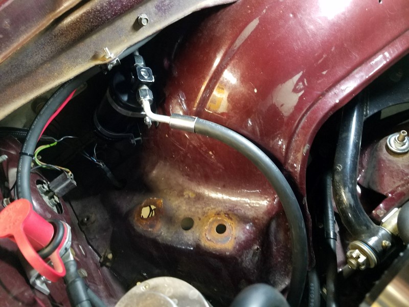
Last night I loosely mounted the drier and started looking at liquid line routing. I was happy to see I should be able to route the line tucked inside the fender and out of sight by using 45 degree fittings on either side of the drier and a 90 degree fitting at the TXV.
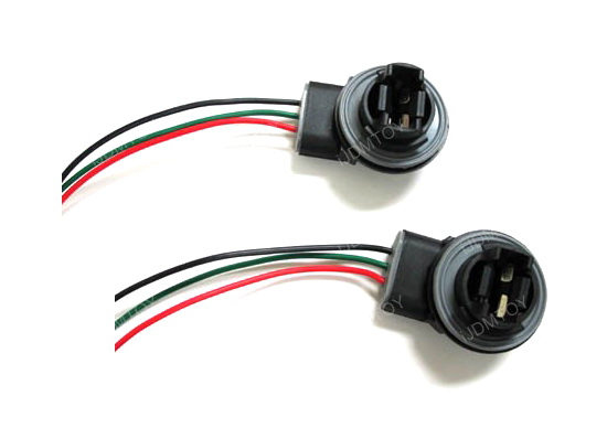
On my Cherokee I had a similar issue with the taillights that also ground to the body with a screw through the housing by converting to a GM 3157 socket and bulbs with a dedicated ground. and that solved the problem,
On my Cherokee I had a similar issue with the taillights that also ground to the body with a screw through the housing by converting to a GM 3157 socket and bulbs with a dedicated ground. and that solved the problem,
What is the part number on these? Do they twist into the Nova rear light housing?
Car looks great Clint! Very interesting about the A/C project you are doing. I'm interested to see how you make out. Keep up the good work!
Thank you! I need to check in on your build too. I don't get onto pro-touring too often.
Update:
Many years ago I picked up compressor fittings from Docs Blocks just before they went out of business. I got both straight and angle/tube adapters and ended up using a combination: straight on the suction side and right angle on the high pressure outlet. Unfortunately the right angle adapter pointed directly at the radiator hose.
The tubing on this outlet adapter is #8 which has a 1/2" outside diameter (number/dash sizes correspond to sixteenths i.e. #8 is 8/16" or 1/2"). I didn't have a 1/2" tubing bender, but I found a cheap hand bender at the local parts store to get the job done.
Now the outlet points in a favorable direction and I will be able to route the high pressure hose with a service port fitting toward the front of the car.
This weekend I borrowed a Mastercool 71550 AC hose crimper and made all the hoses for the system. Here's what a typical fitting looks like coming out of the tool:
This tool is very simple to operate. It comes with dies for sizes 6,8,10, and 12. I marked my fittings and hose on the car to make sure they had the right orientation, then held them in the tool while tightening the large acme screw at the top. This brings the dies together which put indentations around the fitting to clamp the hose. There is a mark on the tool which tells you how far to crimp.
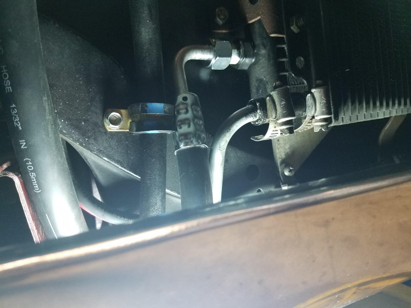
The first hose I made goes from the drier and runs under the fender around to the TXV.
I put a high side service port in the discharge line just after the compressor. I've got a lot of hoses (2x transmission, 2x AC, coolant, coolant overflow) and the starter cable routing through this area and it's starting to get crowded. I had to disconnect the transmission lines while I was doing this so I could rearrange things. If you look on the left of this photo near the heater bypass loop you can see the larger suction line which connects to the compressor with a 45 degree fitting.
The discharge hose goes from the compressor and loops up to the top of the condenser as shown below.
I used a 90 degree fitting at the bottom of the condenser for the liquid line going back to the drier. I had to sneak it between the transmission cooler inlet and return lines.
I saved the expensive shepard's hook fitting for last.
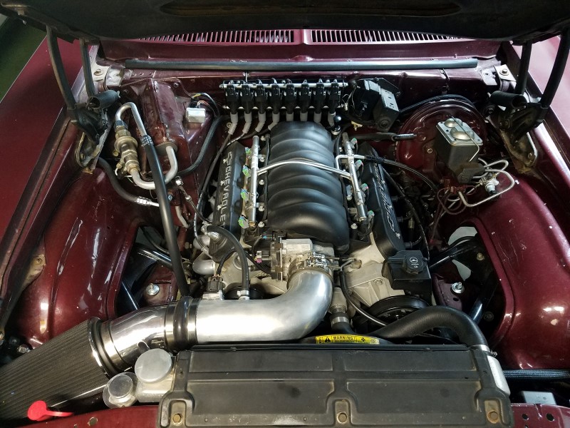
Here is how the engine bay is shaping up now that the AC is fully plumbed.

 08-01-2018, 03:25 PM