
Need some help identifying these conncetors...


 06-05-2009, 10:07 AM
#65
Launching!
Thread Starter
Join Date: Nov 2003
Location: Europe, Netherlands, Amersfoort
Posts: 241
Likes: 0
Received 0 Likes
on
0 Posts

Where can I find that? if it is E40?
What wire size do I need?
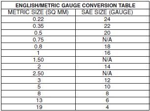
Is the wire size mentioned in those schematics? and is het metric?
Like:
2540
RD/WH
0.5
Peter
What wire size do I need?
Is the wire size mentioned in those schematics? and is het metric?
Like:
2540
RD/WH
0.5
Peter
06-05-2009, 12:39 PM
#66
Launching!
Thread Starter
Join Date: Nov 2003
Location: Europe, Netherlands, Amersfoort
Posts: 241
Likes: 0
Received 0 Likes
on
0 Posts
Thanks AJ,
There is E38 stamped into the metal casing of the ECM.
I think I understand most of it above. I'll have to check in the garage tomorrow.
Any idea where to get new connector pins for the ECM connector? I don't have any wire in C1#1 park/neutral signal...
Great job on the photoshop!
Peter
There is E38 stamped into the metal casing of the ECM.
I think I understand most of it above. I'll have to check in the garage tomorrow.
Any idea where to get new connector pins for the ECM connector? I don't have any wire in C1#1 park/neutral signal...
Great job on the photoshop!
Peter
06-05-2009, 12:42 PM
#67
Thanks AJ,
There is E38 stamped into the metal casing of the ECM.
I think I understand most of it above. I'll have to check in the garage tomorrow.
Any idea where to get new connector pins for the ECM connector? I don't have any wire in C1#1 park/neutral signal...
Great job on the photoshop!
Peter
There is E38 stamped into the metal casing of the ECM.
I think I understand most of it above. I'll have to check in the garage tomorrow.
Any idea where to get new connector pins for the ECM connector? I don't have any wire in C1#1 park/neutral signal...
Great job on the photoshop!
Peter
 06-05-2009, 12:51 PM
#69
Thanks AJ,
There is E38 stamped into the metal casing of the ECM.
I think I understand most of it above. I'll have to check in the garage tomorrow.
Any idea where to get new connector pins for the ECM connector? I don't have any wire in C1#1 park/neutral signal...
Great job on the photoshop!
Peter
There is E38 stamped into the metal casing of the ECM.
I think I understand most of it above. I'll have to check in the garage tomorrow.
Any idea where to get new connector pins for the ECM connector? I don't have any wire in C1#1 park/neutral signal...
Great job on the photoshop!
Peter
05 was an E40
06-05-2009, 02:22 PM
#70
Launching!
Thread Starter
Join Date: Nov 2003
Location: Europe, Netherlands, Amersfoort
Posts: 241
Likes: 0
Received 0 Likes
on
0 Posts
Two questions allready, just by looking.
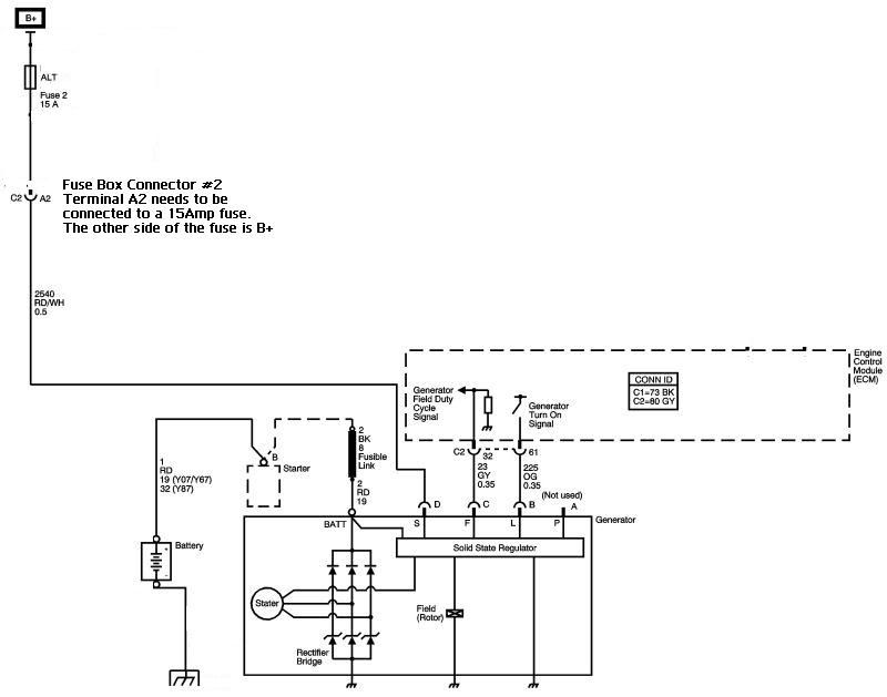
- The RD/WH alt wire comming from the alternator is thinner (0.5mm2) than the alt wire in the American Auto Wire classic update kit. This one is stock color brown, 1mm2 thick and has 13 strands. Orginally it is not fused and it goes to the ignition switch. Could this one be useable if fused correctly? if not I have many options for voltage sensing in the AAW update kit.
- In you schematics you show circuit 439 and 1439?
I need to put ignition voltage on both? ECM pins C1#19 (MM6) and C1#47 and does C1#59 Ingintion relay control has anything to do with these? I havn't seen it on the schematics jet...?
Thanks
Peter

 06-06-2009, 07:07 AM
#73
Two questions allready, just by looking.
- The RD/WH alt wire comming from the alternator is thinner (0.5mm2) than the alt wire in the American Auto Wire classic update kit. This one is stock color brown, 1mm2 thick and has 13 strands. Orginally it is not fused and it goes to the ignition switch. Could this one be useable if fused correctly? if not I have many options for voltage sensing in the AAW update kit.
- In you schematics you show circuit 439 and 1439?
I need to put ignition voltage on both? ECM pins C1#19 (MM6) and C1#47 and does C1#59 Ingintion relay control has anything to do with these? I havn't seen it on the schematics jet...?
Thanks
Peter
 06-06-2009, 09:58 AM
#74
11 Second Club
Join Date: Mar 2008
Location: New Westminster, B.C., Canada
Posts: 445
Likes: 0
Received 1 Like
on
1 Post
I was under the impression that I could remove certain things (evap, 2nd O2 sensors, vats, skip shift solenoid, reverse lock out solenoid, fuel level sender)((that I rememberanyway)) and then disable them using a tuner program, and that that would work. If you are saying that that will only stop codes from coming up and that the car will run in limp mode, then I need to rethink this entire thing.
06-06-2009, 10:09 AM
#75
Ok, but does the stock 1971 camaro fuel level guage sender give the same voltage/resistance output? I don't know anything about OBD1 car stuff, or for that matter OBD2 stuff either really... I'm just trying to figure it out. In any case, if the pcm is looking for a certain resistance from the fuel sender, could I use an appropriate resistor in that circuit instead? To fool the computer into thinking the tank was full? I don't want to run the evap system either.
I was under the impression that I could remove certain things (evap, 2nd O2 sensors, vats, skip shift solenoid, reverse lock out solenoid, fuel level sender)((that I rememberanyway)) and then disable them using a tuner program, and that that would work. If you are saying that that will only stop codes from coming up and that the car will run in limp mode, then I need to rethink this entire thing.
I was under the impression that I could remove certain things (evap, 2nd O2 sensors, vats, skip shift solenoid, reverse lock out solenoid, fuel level sender)((that I rememberanyway)) and then disable them using a tuner program, and that that would work. If you are saying that that will only stop codes from coming up and that the car will run in limp mode, then I need to rethink this entire thing.
06-06-2009, 10:24 AM
#76
OK lets try again
The Charging System
The Cranking System

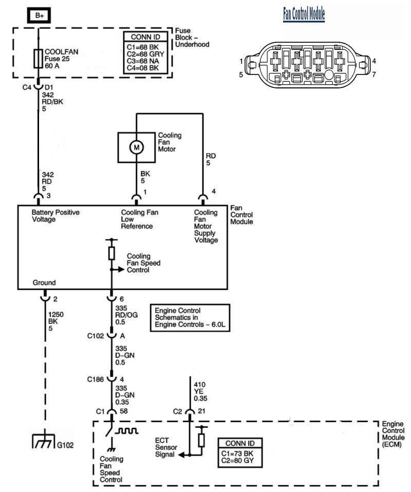
The Cooling Fan
The ECM & TCM Battery Circuits
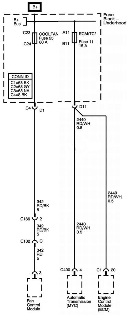
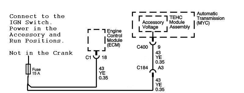
The ECM & TCM Accessory Circuits
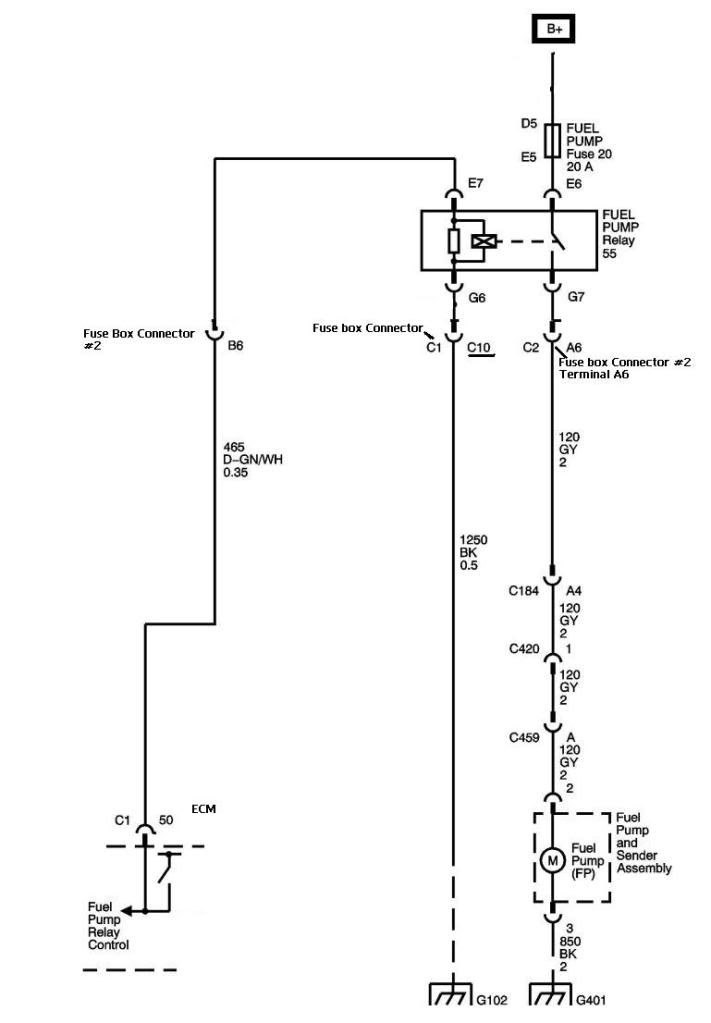
The Fuel Pump Circuit
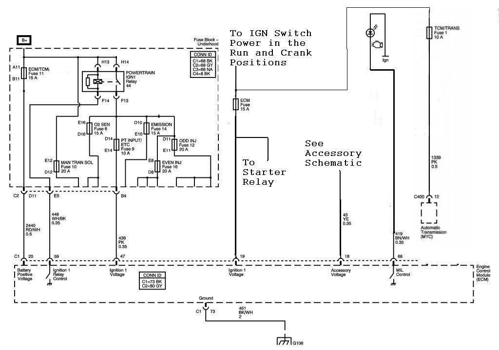
The ECM MIL, Ignition Switch, Ground and Powertrain IGN1 Circuits
Revised Powertrain IGN 1 Relay Circuit
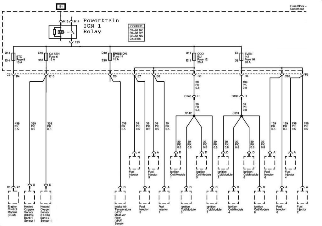
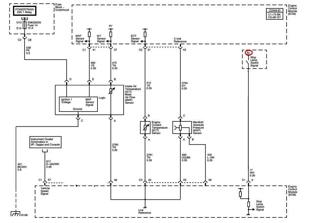
Powertrain IGN 1 Engine Data Sensors
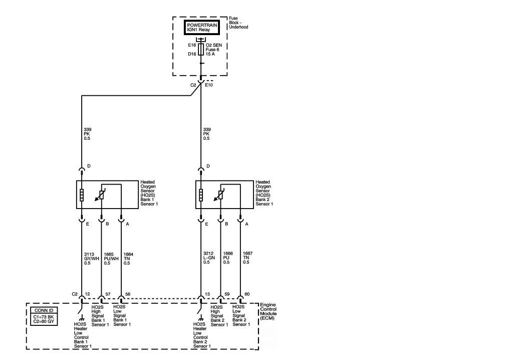
Powertrain IGN 1 O2 sensor Circuits
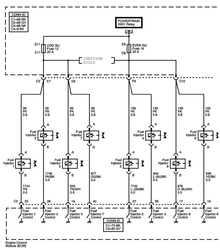
Powertrain IGN 1 Injector Circuits

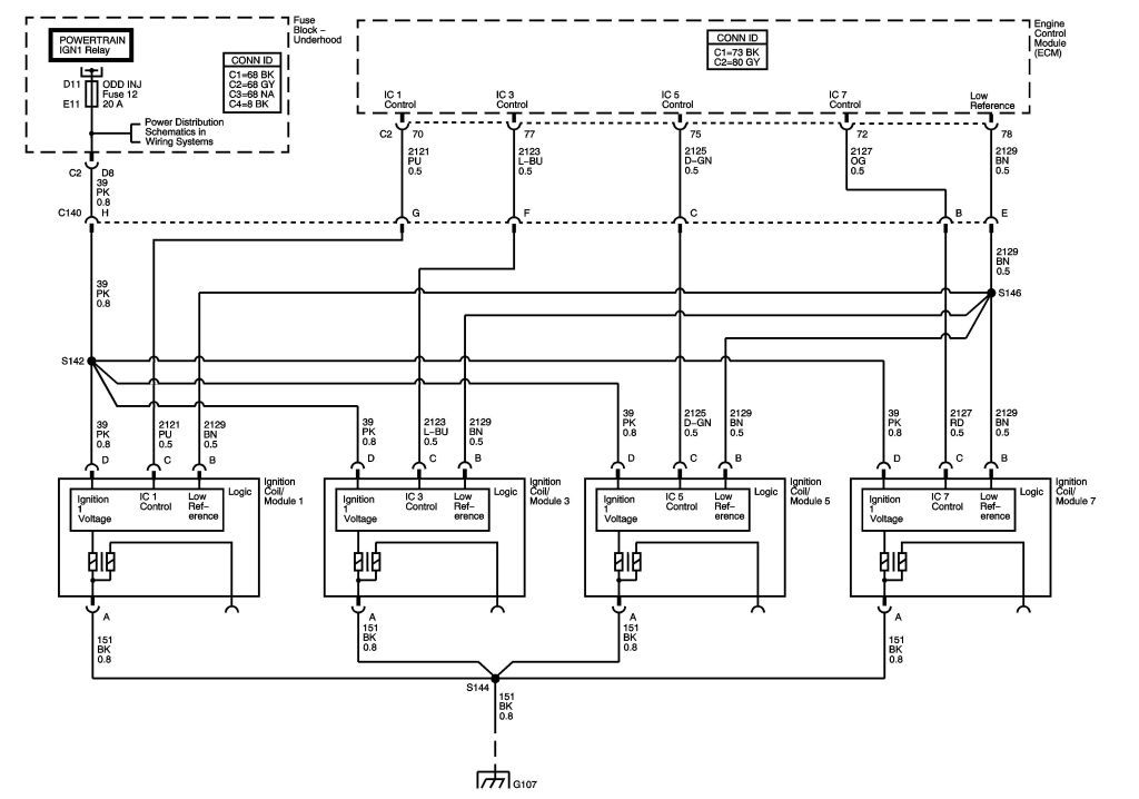
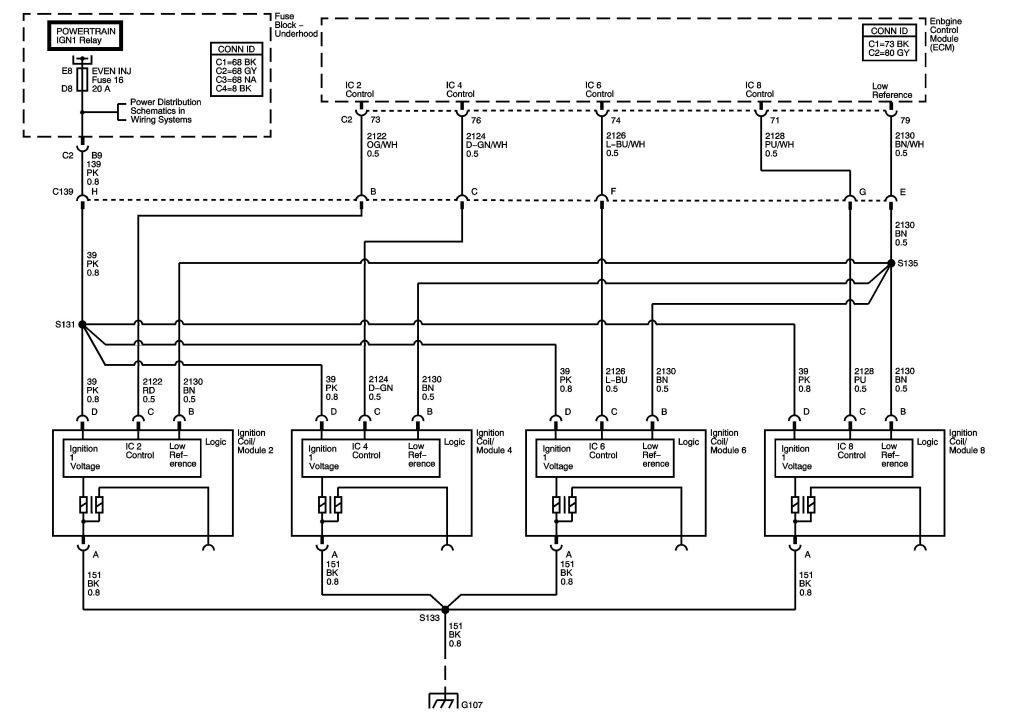
Powertrain IGN 1 Bank 1 Ignition Control Circuits
Powertrain IGN 1 Bank 2 Ignition Control Circuits
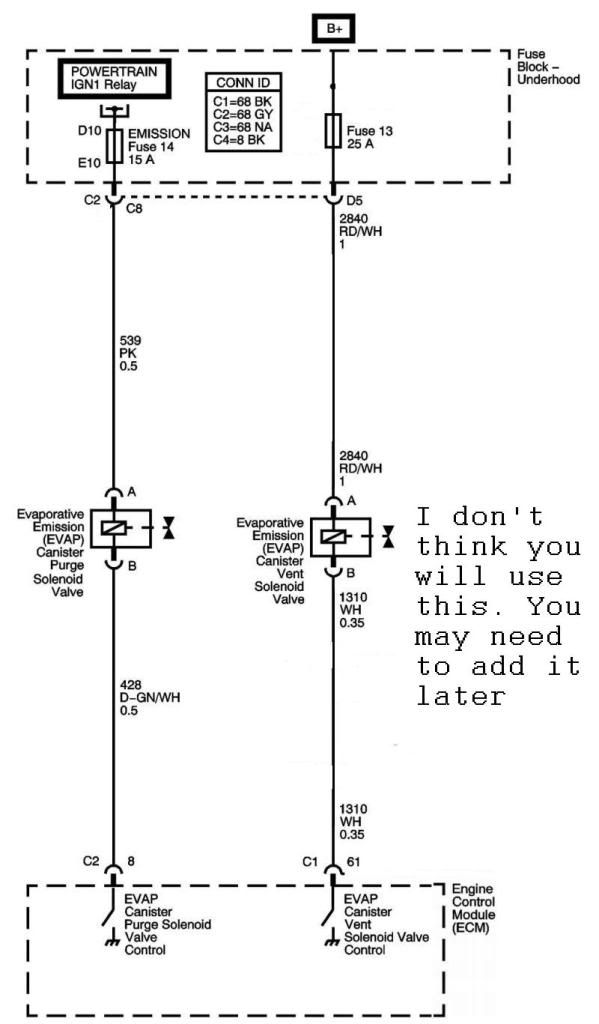
Powertrain and Battery Feed EVAP Circuits
(you may not use the Vent Solenoid)
The Charging System
The Cranking System
The Cooling Fan
The ECM & TCM Battery Circuits
The ECM & TCM Accessory Circuits
The Fuel Pump Circuit
The ECM MIL, Ignition Switch, Ground and Powertrain IGN1 Circuits
Revised Powertrain IGN 1 Relay Circuit
Powertrain IGN 1 Engine Data Sensors
Powertrain IGN 1 O2 sensor Circuits
Powertrain IGN 1 Injector Circuits
Powertrain IGN 1 Bank 1 Ignition Control Circuits
Powertrain IGN 1 Bank 2 Ignition Control Circuits
Powertrain and Battery Feed EVAP Circuits
(you may not use the Vent Solenoid)
06-06-2009, 11:42 AM
#78
Launching!
Thread Starter
Join Date: Nov 2003
Location: Europe, Netherlands, Amersfoort
Posts: 241
Likes: 0
Received 0 Likes
on
0 Posts
WOW! GREAT STUFF!!! I will lock myself up in the garage tonight!
- Another question about the fuel level signal the ECM needs:
What is the normal resistance at full? and what is the normal resistance at empty?
I have a two wire in tank fuel level sender that reads 0 Ohm @ empty to 90 Ohm @ full for the Autometer gauge. Would that work?
- Another question:
I do NOT have the fan speed control module from the corvette unfortunadly. Besides that I have a dual 18"> 16" fan setup from a Lincoln Continental.
Is there another way to use the fan speed controle wire from the ECM to run my dual fan setup? I prefer: low speed single fan and high speed dual fan.
Is this possible to make?
THANKS
Peter
Last edited by pjtimmer; 06-06-2009 at 12:28 PM.
06-06-2009, 09:56 PM
#79

How is the RUN/CRANK relay in the circuit above ever going to be tripped? Another way of asking the question is what is driving the Starter Enable Relay Control signal from the ECM to ever go low? Normally this would be handled by the ECM after receiving instructions over the CANBUS from the BCM. Without the BCM, how would it work? I'm not trying to be critical. I'm just asking for clarification in case I missed something.
06-06-2009, 10:07 PM
#80
How is the RUN/CRANK relay in the circuit above ever going to be tripped? Another way of asking the question is what is driving the Starter Enable Relay Control signal from the ECM to ever go low? Normally this would be handled by the ECM after receiving instructions over the CANBUS from the BCM. Without the BCM, how would it work? I'm not trying to be critical. I'm just asking for clarification in case I missed something.
I guess I need to look at the Cal file and see what needs to be switched over.