
Need some help identifying these conncetors...
 06-02-2009, 12:33 PM
#41
Launching!
Thread Starter
Join Date: Nov 2003
Location: Europe, Netherlands, Amersfoort
Posts: 241
Likes: 0
Received 0 Likes
on
0 Posts

You're welcome.
Don't bother to look into hooking it to older cars fuse box. If I look at most aftermarket ls2 harnesses, most of them have universial fuse boxes. In the end I just need about 6 fuses and 4 relays... isn't it?
If you can answer the questions in my last exel sheet , I will be one step closer.
Please take in consideration that I probably need some MYC wires that are not there in my old MM6 harness. Like Park/Neutral signal C1#1. I have no idea what I miss.
Thanks
Peter
 06-02-2009, 12:41 PM
#42

Yes I should fined some time tonight.
Wait until you see what the inside of the OEM fuse box looks like. I will post a picture.
Ummmmm I just looked and I don't have any here they are at my other house in Charlotte Maybe I have one left at work.
To replicate this will take some work.
Wait until you see what the inside of the OEM fuse box looks like. I will post a picture.
Ummmmm I just looked and I don't have any here they are at my other house in Charlotte
Maybe I have one left at work. To replicate this will take some work.
06-02-2009, 01:07 PM
#43
Launching!
Thread Starter
Join Date: Nov 2003
Location: Europe, Netherlands, Amersfoort
Posts: 241
Likes: 0
Received 0 Likes
on
0 Posts
Would it be intersting to buy th DIY kit form currentperformance http://www.currentperformance.com/Ac...iring_acc.html
Peter
Peter
06-03-2009, 01:23 AM
#45
Launching!
Thread Starter
Join Date: Nov 2003
Location: Europe, Netherlands, Amersfoort
Posts: 241
Likes: 0
Received 0 Likes
on
0 Posts
You're right.
I emailed cleveland pick-a-part also for that fuse box. Havn't heard jet.
Gues I also need those gray connector blocks... do you where I can get new pins that go into the gray blocks? and new pins for the ECM connectors?
thanks
Peter
I emailed cleveland pick-a-part also for that fuse box. Havn't heard jet.
Gues I also need those gray connector blocks... do you where I can get new pins that go into the gray blocks? and new pins for the ECM connectors?
thanks
Peter
06-03-2009, 07:04 AM
#46
Ouch. I take that as you chopped them off?
Maybe plan B is your only option.
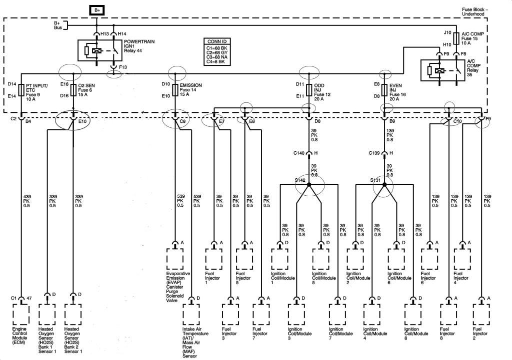
Let me print the fuse box flow out today and really look it over . You are going to have a lot I mean a lot of splices.
Just on the Power-Train Ignition #1 Circuit (not everything on IGN #1) you will have possibly 6 splices coming out of the IGN #1 relay going to 5 fuses and 7 more splices. That will be 13 splices off of 1 relay and I am not including all of the fuses because they are single wire connections.
I think I may have missed some
I see 9 wire coming off fuse #12
Maybe plan B is your only option.
Let me print the fuse box flow out today and really look it over . You are going to have a lot I mean a lot of splices.
Just on the Power-Train Ignition #1 Circuit (not everything on IGN #1) you will have possibly 6 splices coming out of the IGN #1 relay going to 5 fuses and 7 more splices. That will be 13 splices off of 1 relay and I am not including all of the fuses because they are single wire connections.
I think I may have missed some
I see 9 wire coming off fuse #12
06-03-2009, 12:13 PM
#47
Launching!
Thread Starter
Join Date: Nov 2003
Location: Europe, Netherlands, Amersfoort
Posts: 241
Likes: 0
Received 0 Likes
on
0 Posts
Yep, ouch... Time for plan B.
I might be able to add a distribution block to the Ign relay, so it would be easier to splice/ distribute all those wires.
I am not to worried about this part, as long as I know what to do with all the wires in my exel sheet...
Thanks
Peter
I might be able to add a distribution block to the Ign relay, so it would be easier to splice/ distribute all those wires.
I am not to worried about this part, as long as I know what to do with all the wires in my exel sheet...
Thanks
Peter
06-03-2009, 01:02 PM
#50
This is the simplest one (I think)
This is the Fuel Pump Circuits
The ECM turns on the Relay from Connector #1 terminal #50. This D-GM/WHT wire should be in the Fuse Box Connector #2 Terminal B6 and it need to go to the control side of the relay
The Ground wire that is located in the Fuse Box Connector #1 Terminal C10 can be used or just hook up a ground to the other side of the Control side of the relay
Battery feed to the relay should have a 20 amp fuse
The Fuel Pump Feed wire is in the Fuse Box Connector #2 Terminal A6. This wire is grey and goes to the Pump it is on the other side from the B+
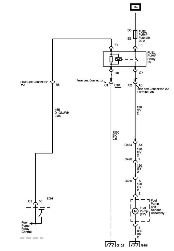
I hope I did that correctly.
This is the Fuel Pump Circuits
The ECM turns on the Relay from Connector #1 terminal #50. This D-GM/WHT wire should be in the Fuse Box Connector #2 Terminal B6 and it need to go to the control side of the relay
The Ground wire that is located in the Fuse Box Connector #1 Terminal C10 can be used or just hook up a ground to the other side of the Control side of the relay
Battery feed to the relay should have a 20 amp fuse
The Fuel Pump Feed wire is in the Fuse Box Connector #2 Terminal A6. This wire is grey and goes to the Pump it is on the other side from the B+
I hope I did that correctly.

 06-04-2009, 10:04 AM
#55
Launching!
Thread Starter
Join Date: Nov 2003
Location: Europe, Netherlands, Amersfoort
Posts: 241
Likes: 0
Received 0 Likes
on
0 Posts
06-04-2009, 10:47 PM
#56
Peter I was very busy today. I got some new toys hooked up in a customers/friends car today. I am 1/2 way home on hooking up evrything. I have another data loger on top of this one to install. This one is not run through the ECM. This one has it's own set of sensors.
I am on the wrong TPS circuit. I am on the 5V closed and 0V WOT, but it doesn't look good for a $7000 dyno tune.
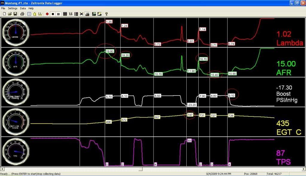
I am on the wrong TPS circuit. I am on the 5V closed and 0V WOT, but it doesn't look good for a $7000 dyno tune.
 first te make te car work.