


1937 Ford LS2 Install

Thread Starter
TECH Fanatic


Joined: Jul 2008
Posts: 1,570
Likes: 173
Thread Starter
TECH Fanatic
Joined: Jul 2008
Posts: 1,570
Likes: 173
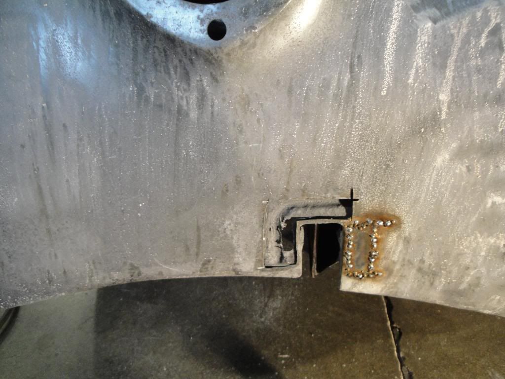
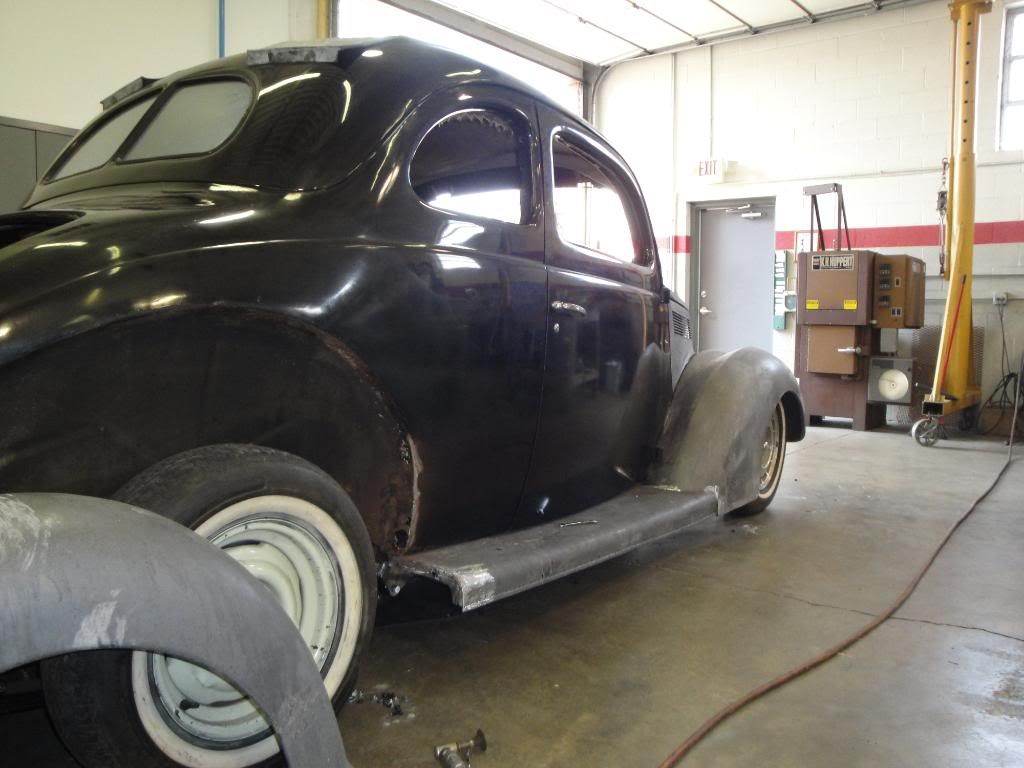
Just about finished with the front sheetmetal alignment....got the Hood repaired and fitted......
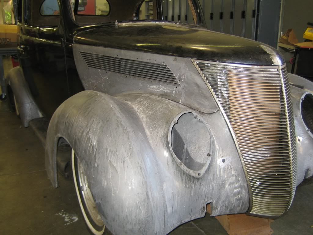
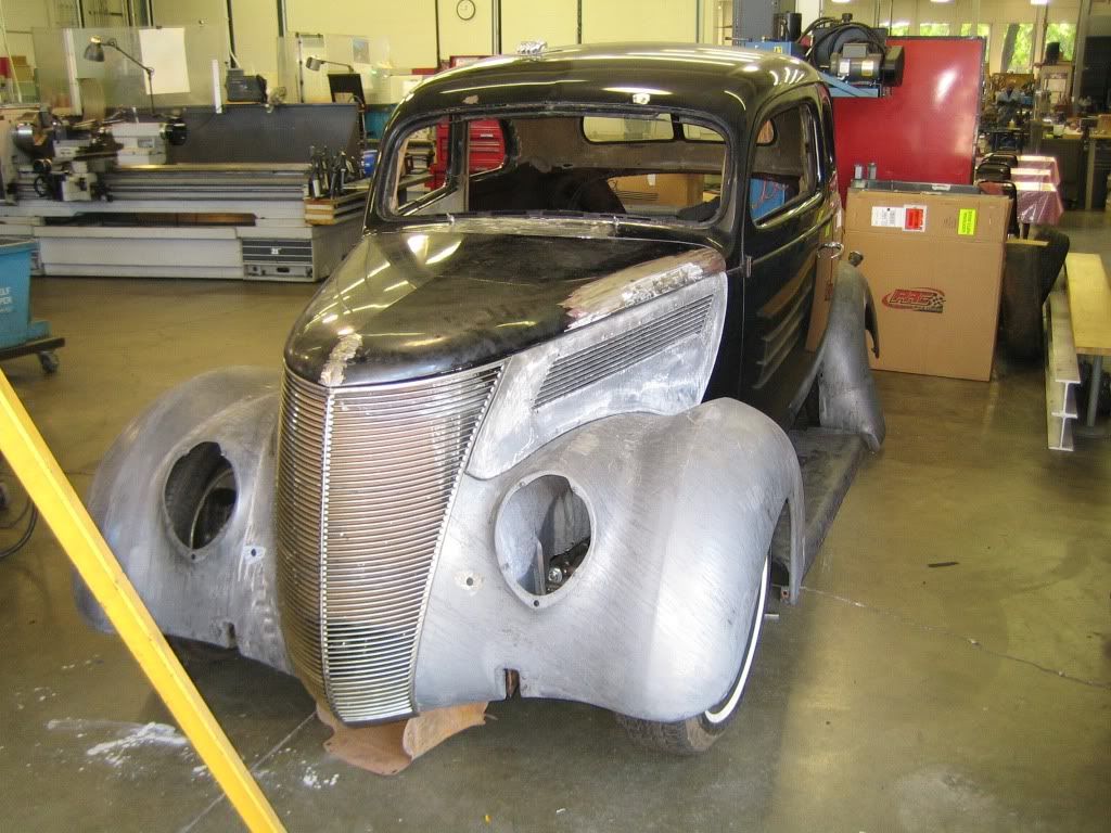
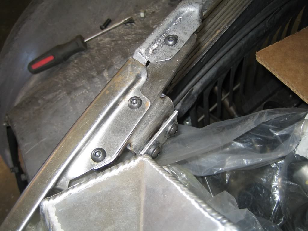
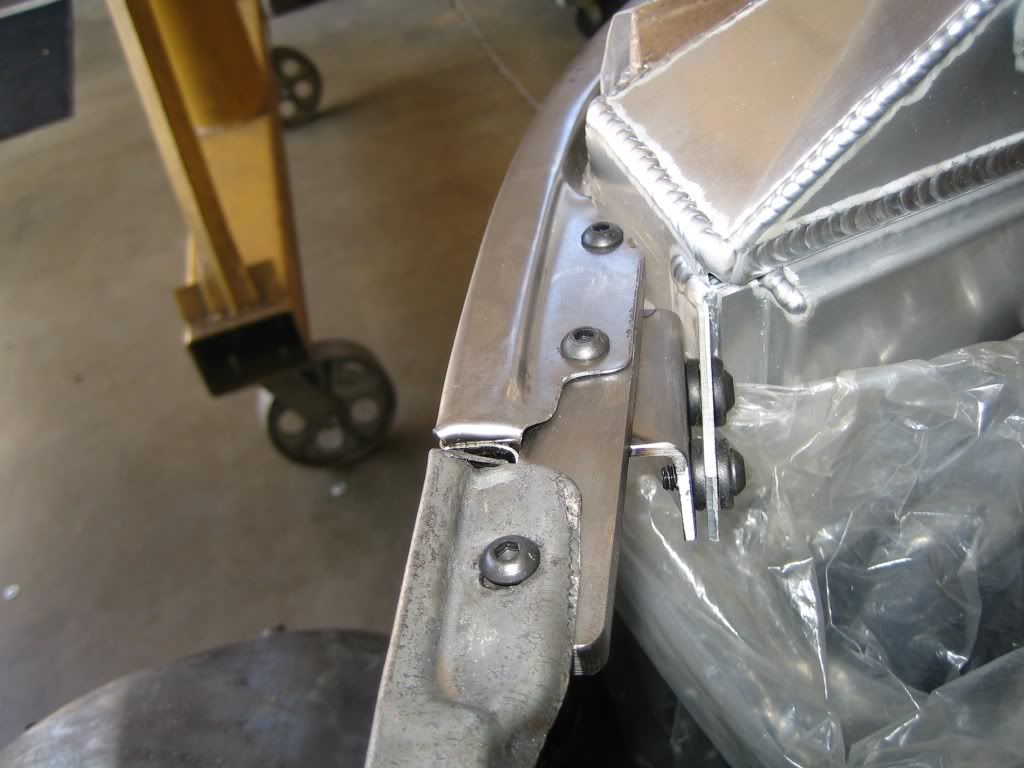
On a 37.....the Hood sides, Grille, and Radiator locating features are controlled by a mounting Bracket where all the pieces come together .....I ended up making my own as the Ford would have to be modified heavily for the mounting of the aftermarket Radiator......New part made from 1/4" mild steel and the Upper Radiator mounting tabs are connected thru Rubber Bushings and the bottom of the radiator also mounted in Rubber.....
Next week I'll be patching the bad spot's in the fenders than move on to mounting the running boards and rear fenders........
Ken
Thread Starter
TECH Fanatic
Joined: Jul 2008
Posts: 1,570
Likes: 173
Ken
Thread Starter
TECH Fanatic
Joined: Jul 2008
Posts: 1,570
Likes: 173
Bought a GTO Fuel tank set-up today for $100.....Great Idea from Ls1Nova....Bonus is that in addition to getting the sending unit, the fuel pump assy might be able to be used also..........That's what's great about this site..........Thanks again to all that have supplied info along the way......"And"....I still have a long way to go..........Tank should be here in a couple of days
Ken
Thread Starter
TECH Fanatic
Joined: Jul 2008
Posts: 1,570
Likes: 173
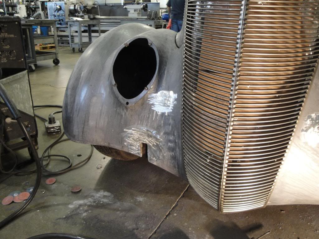
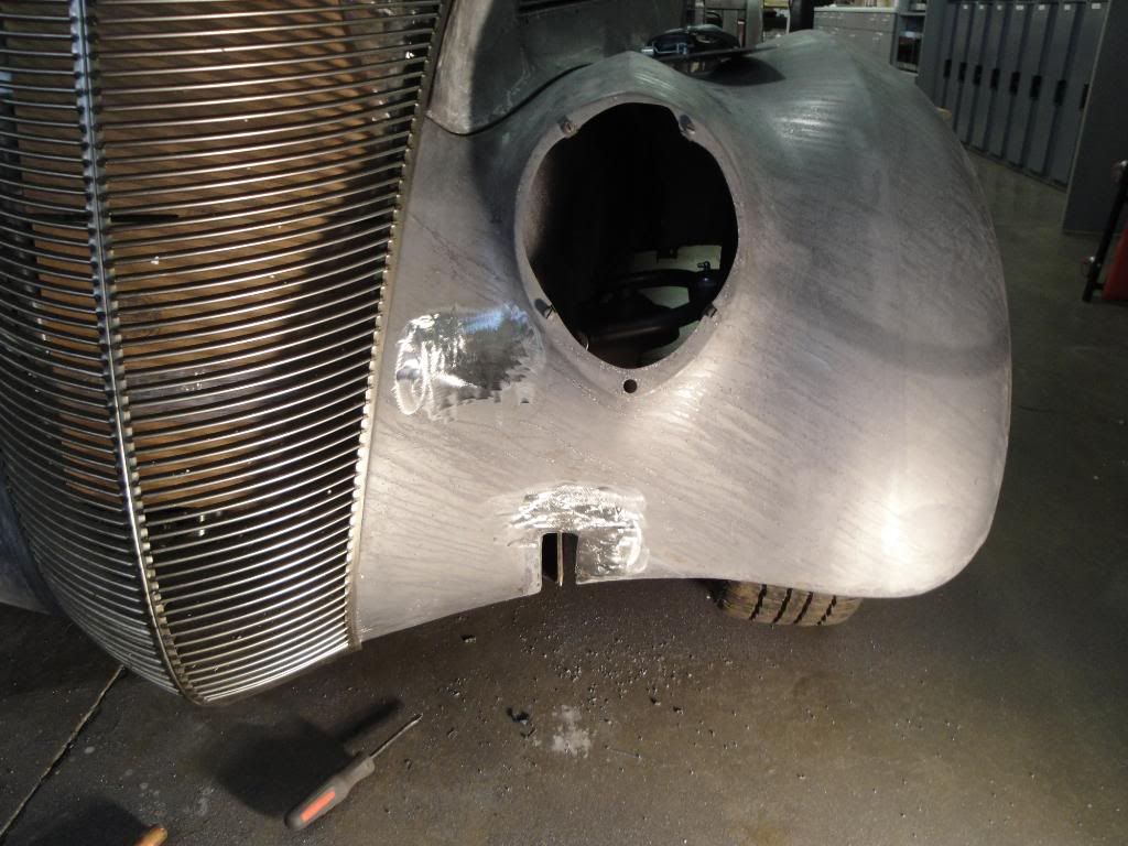
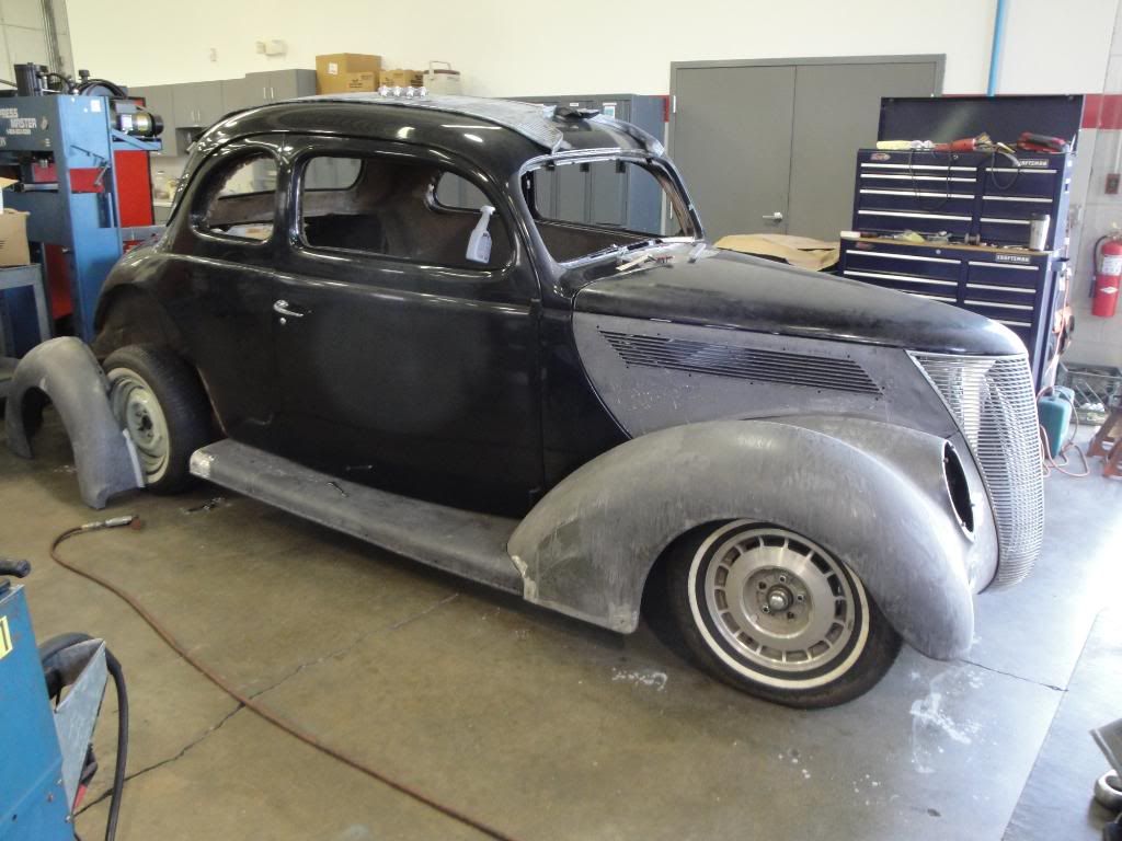
Been doing the little detail things that take a lot of time , so a lot of progress is being made....yet....it doesn't look like much has happened......Got the Windshield wiper assembly fit, installed "And" working.....Tight fit with the A.C. unit but what else is new....LOL
Also filled the holes in the front fenders were used for mounting turn signals....."And" patched some "Weak" areas in the fenders and the Running Boards.....Here are some Pic's..
Ken
Also filled the holes in the front fenders were used for mounting turn signals....."And" patched some "Weak" areas in the fenders and the Running Boards.....Here are some Pic's..
Ken
Thread Starter
TECH Fanatic
Joined: Jul 2008
Posts: 1,570
Likes: 173
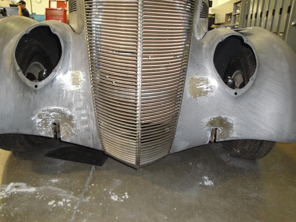
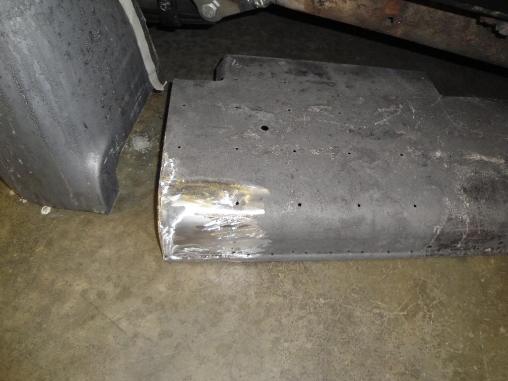
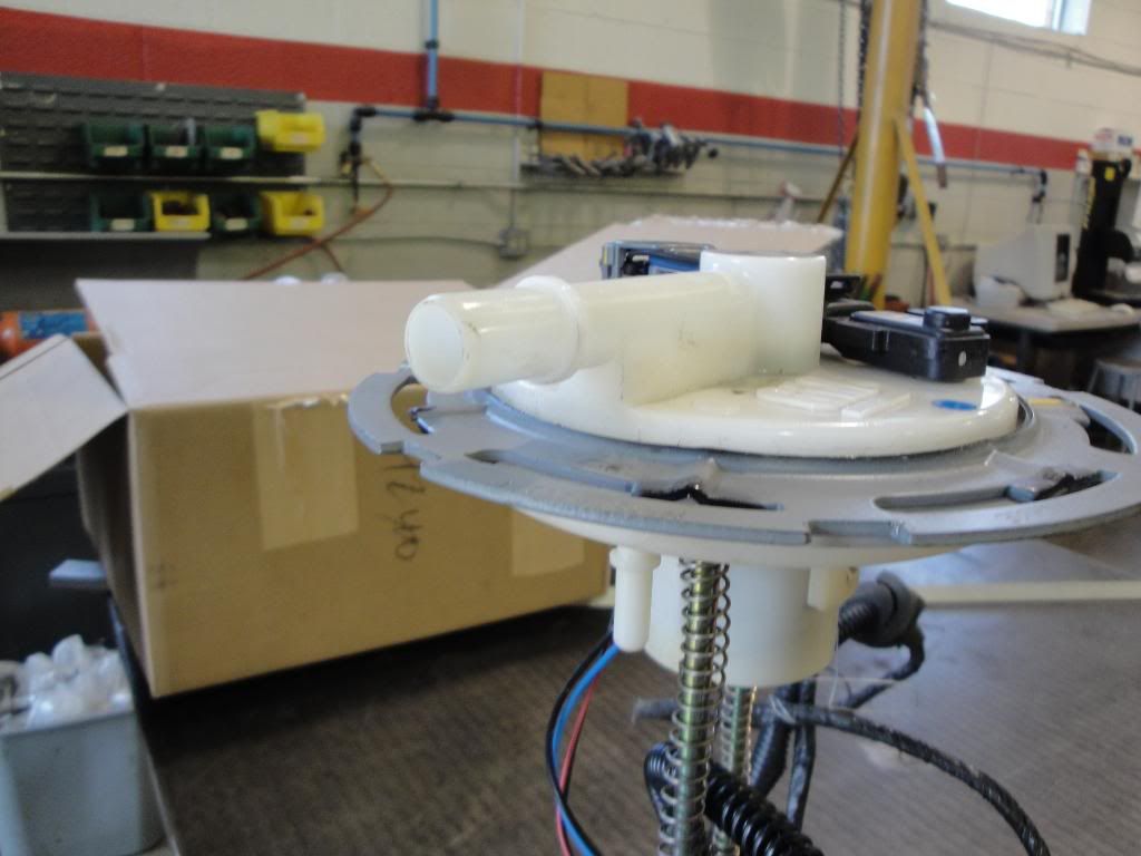
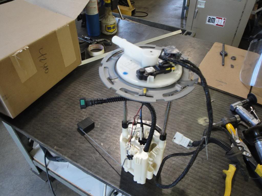
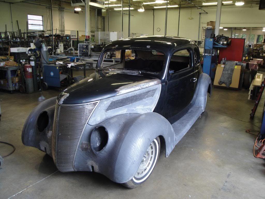
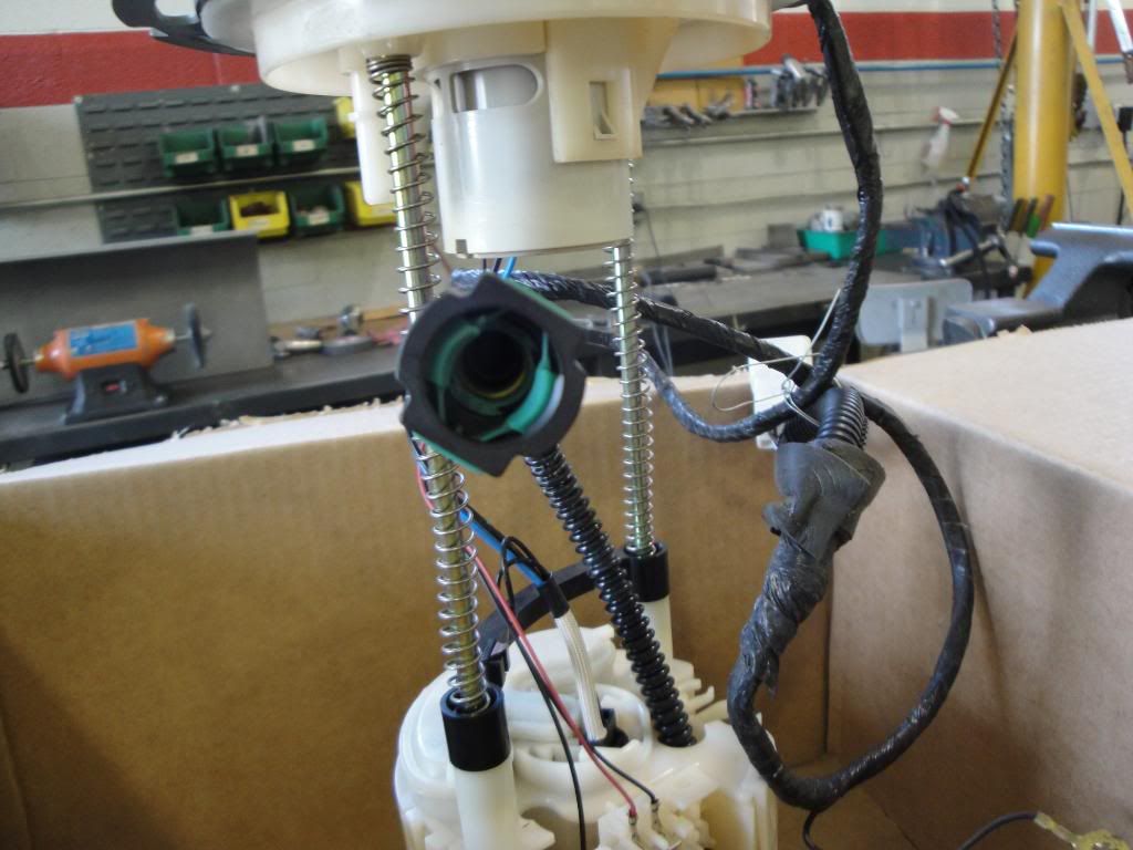
Got the Front fenders finished and started mounting the Running Boards.....Boring Stuff ........But.......Now I need some of the expertise from this you guy's.......I got the GTO Pump/Sender unit today......Again....I'm going to use the GTO Dash Gauge module and as it was suggested here to use the Pump/Sender to make the fuel gauge work........I see that the Pump Module is spring loaded down to keep the unit at the bottom of the tank.....I can modify it to fit.........But........Looking at the pic's......What go's where???............I need input so I can plan it out.....I can make stuff, but this is where your help is needed........Also.....the Harness assy is on it's way back from Speartech........
and........The Boring sheetmetal pic's...........
Ken
and........The Boring sheetmetal pic's...........
Ken
LS1 Tech Stories
The Best V8 Stories One Small Block at Time

6 Common C5 Corvette Failures and What's Involved In Repairing Them
Pouria Savadkouei
Retro Modern Bandit Pontiac Trans AM Comes With Burt Reynolds' Autograph
Verdad Gallardo
Top 10 Greatest Cadillac V Series Performance Models Ever, Ranked
Pouria Savadkouei
Top 10 Most Powerful Chevy Trucks Ever Made!

Hennessey's New Supercharged Silverado ZR2 Has 700 HP
Verdad Gallardo
Coachbuilt N2A Anteros Is an LS2-Powered C6 Corvette In Italian Clothes
Verdad Gallardo
Awesome K5 Blazer Restomod Comes With C7 Corvette Power
Verdad Gallardo
10 Camaros You Should Never Buy

10 LS Engine Myths That Refuse to Die
Verdad Gallardo Does the sender not have any fittings on top of it? The big tube on top looks like a vent of some sort, and the line coming from the pump, it doesn't hook to the top of the sender? I'm not familiar with the GTO stuff, but the F body sender is all one unit. To mount it check out this thread https://ls1tech.com/forums/conversio...llon-tank.html About the 4th post G-Body posted a link on how to mount the plastic sender in a tank.
I'm going to do some checking on the GTO sender, looks like we're missing something, but I don't think it's anything too bad.
I'm going to do some checking on the GTO sender, looks like we're missing something, but I don't think it's anything too bad.
Thread Starter
TECH Fanatic
Joined: Jul 2008
Posts: 1,570
Likes: 173
I got the Harnesses and Computer back from Speartech.......Now I need to finish all the "Boring" sheetmetal work finished so I can get into the interesting part of the build.............Any suggestions about how to set-up the GTO pump set-up????
Ken
Ken
Thread Starter
TECH Fanatic
Joined: Jul 2008
Posts: 1,570
Likes: 173
I'm going to do some checking on the GTO sender, looks like we're missing something, but I don't think it's anything too bad.
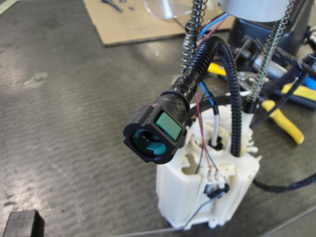
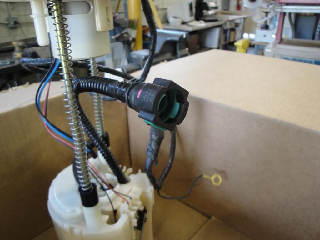
It seems that the only opening in the top of the unit is a vent or return line??........Don't know.......
Ken
It seems that the only opening in the top of the unit is a vent or return line??........Don't know.......
Ken
OK, the fitting on top of the sender is the (EVAP) vapor line, and the line that isn't connected to anything is the fuel feed line. The service manual says you are supposed to pull the sender part way out, then reach in the tank and unhook the feed line quick connect. So you will have to get the male fitting for the quick disconnect and weld it in the tank, unless you can find one that would maybe bolt in, but I'm not sure. Once you get that part done, and get the sender mounted in, you're basically done. The GTO pump module has the fuel pressure regulator, and fuel filter built into it.
This is the system description the way ALLDATA describes it..
"The fuel tank stores the fuel supply. An electric turbine style fuel pump attaches to the fuel senderassembly inside the fuel tank. The fuel pump supplies high pressure fuel through the fuel filter and the fuel feed pipe to the fuel injection system. The fuel pump provides fuel at a higher rate than is needed by the fuel injection system. The fuel pump also supplies fuel to a venturi pump located on the bottom of the fuel sender assembly. The function of the venturi pump is to fill the fuel sender assembly reservoir. The fuel pressure regulator, a part of the fuel sender assembly, maintains the correct fuel pressure to the fuel injection system. The fuel pump and sender assembly contains a reverse flow check valve. The check valve and the fuel pressure regulator maintain fuel pressure in the fuel feed pipe and the fuel rail in order to prevent long cranking times"
And about the fuel filter, it say this...
"The fuel filter assembly is contained within the modular fuel pump and sender assembly reservoir and forms the containment housing for the fuel pump"
It also says that the filter is replaceable, and tells how to do it.


Thread Starter
TECH Fanatic
Joined: Jul 2008
Posts: 1,570
Likes: 173
OK, the fitting on top of the sender is the (EVAP) vapor line, and the line that isn't connected to anything is the fuel feed line. The service manual says you are supposed to pull the sender part way out, then reach in the tank and unhook the feed line quick connect. So you will have to get the male fitting for the quick disconnect and weld it in the tank, unless you can find one that would maybe bolt in, but I'm not sure. Once you get that part done, and get the sender mounted in, you're basically done. The GTO pump module has the fuel pressure regulator, and fuel filter built into it.
This is the system description the way ALLDATA describes it..
"The fuel tank stores the fuel supply. An electric turbine style fuel pump attaches to the fuel senderassembly inside the fuel tank. The fuel pump supplies high pressure fuel through the fuel filter and the fuel feed pipe to the fuel injection system. The fuel pump provides fuel at a higher rate than is needed by the fuel injection system. The fuel pump also supplies fuel to a venturi pump located on the bottom of the fuel sender assembly. The function of the venturi pump is to fill the fuel sender assembly reservoir. The fuel pressure regulator, a part of the fuel sender assembly, maintains the correct fuel pressure to the fuel injection system. The fuel pump and sender assembly contains a reverse flow check valve. The check valve and the fuel pressure regulator maintain fuel pressure in the fuel feed pipe and the fuel rail in order to prevent long cranking times"
And about the fuel filter, it say this...
"The fuel filter assembly is contained within the modular fuel pump and sender assembly reservoir and forms the containment housing for the fuel pump"
It also says that the filter is replaceable, and tells how to do it.
This is the system description the way ALLDATA describes it..
"The fuel tank stores the fuel supply. An electric turbine style fuel pump attaches to the fuel senderassembly inside the fuel tank. The fuel pump supplies high pressure fuel through the fuel filter and the fuel feed pipe to the fuel injection system. The fuel pump provides fuel at a higher rate than is needed by the fuel injection system. The fuel pump also supplies fuel to a venturi pump located on the bottom of the fuel sender assembly. The function of the venturi pump is to fill the fuel sender assembly reservoir. The fuel pressure regulator, a part of the fuel sender assembly, maintains the correct fuel pressure to the fuel injection system. The fuel pump and sender assembly contains a reverse flow check valve. The check valve and the fuel pressure regulator maintain fuel pressure in the fuel feed pipe and the fuel rail in order to prevent long cranking times"
And about the fuel filter, it say this...
"The fuel filter assembly is contained within the modular fuel pump and sender assembly reservoir and forms the containment housing for the fuel pump"
It also says that the filter is replaceable, and tells how to do it.
Thanks "Again"
Ken
Thread Starter
TECH Fanatic
Joined: Jul 2008
Posts: 1,570
Likes: 173
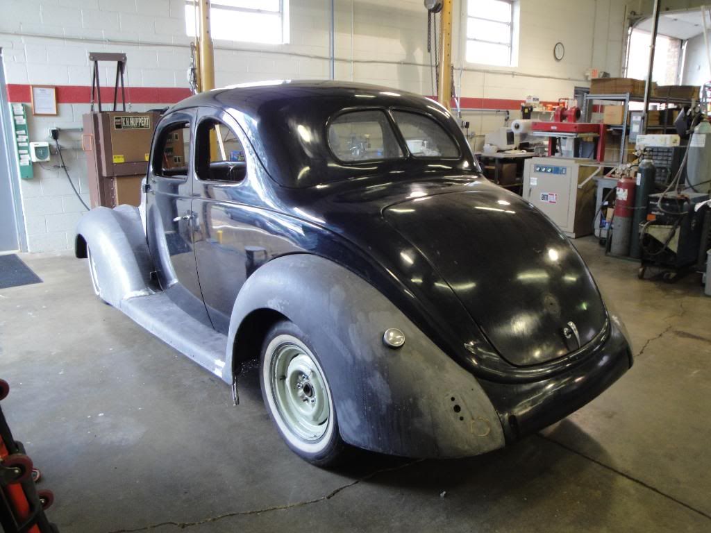
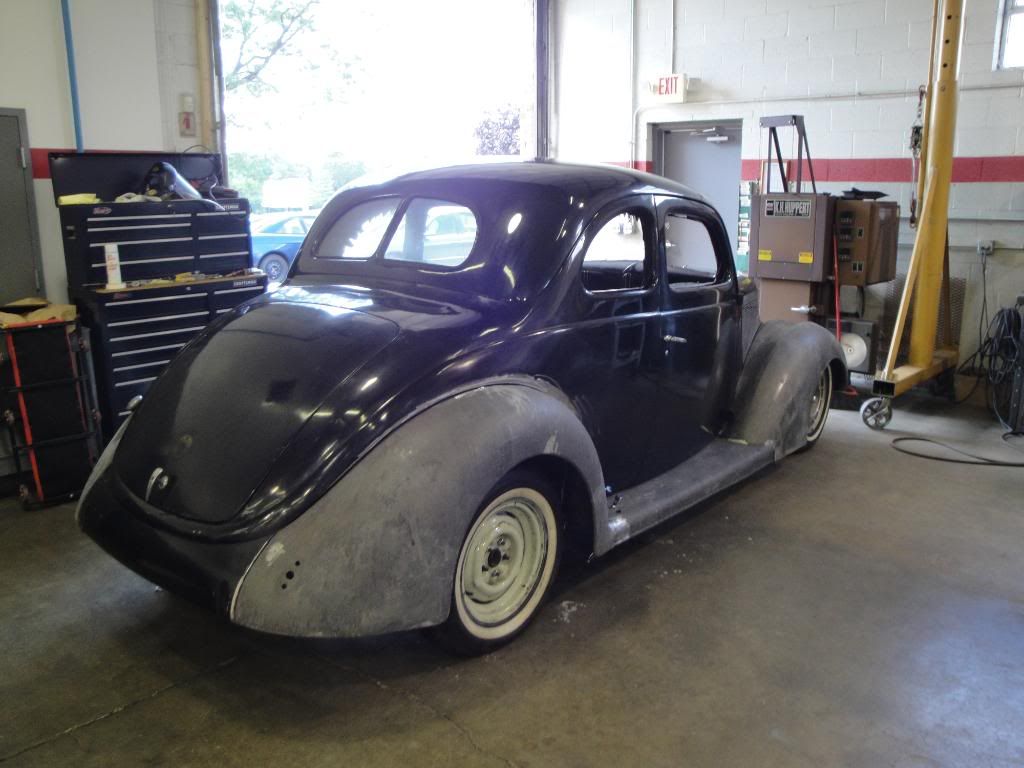
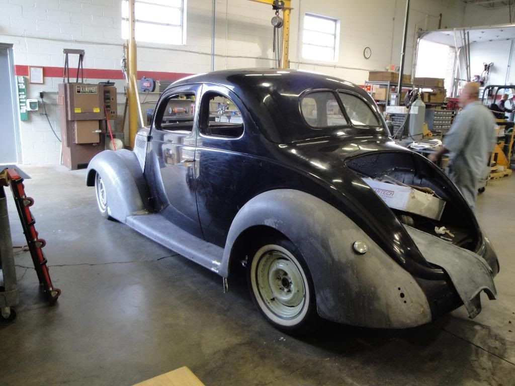
Got most of the Sheetmetal work taken care of and I put all the parts back on and got the car down on the ground......Still a long way to go......But......we came a long way from where we started.......Now, I can get more involved in the "Fun" stuff........Here are some pic's from today
Ken
Ken
Thread Starter
TECH Fanatic
Joined: Jul 2008
Posts: 1,570
Likes: 173
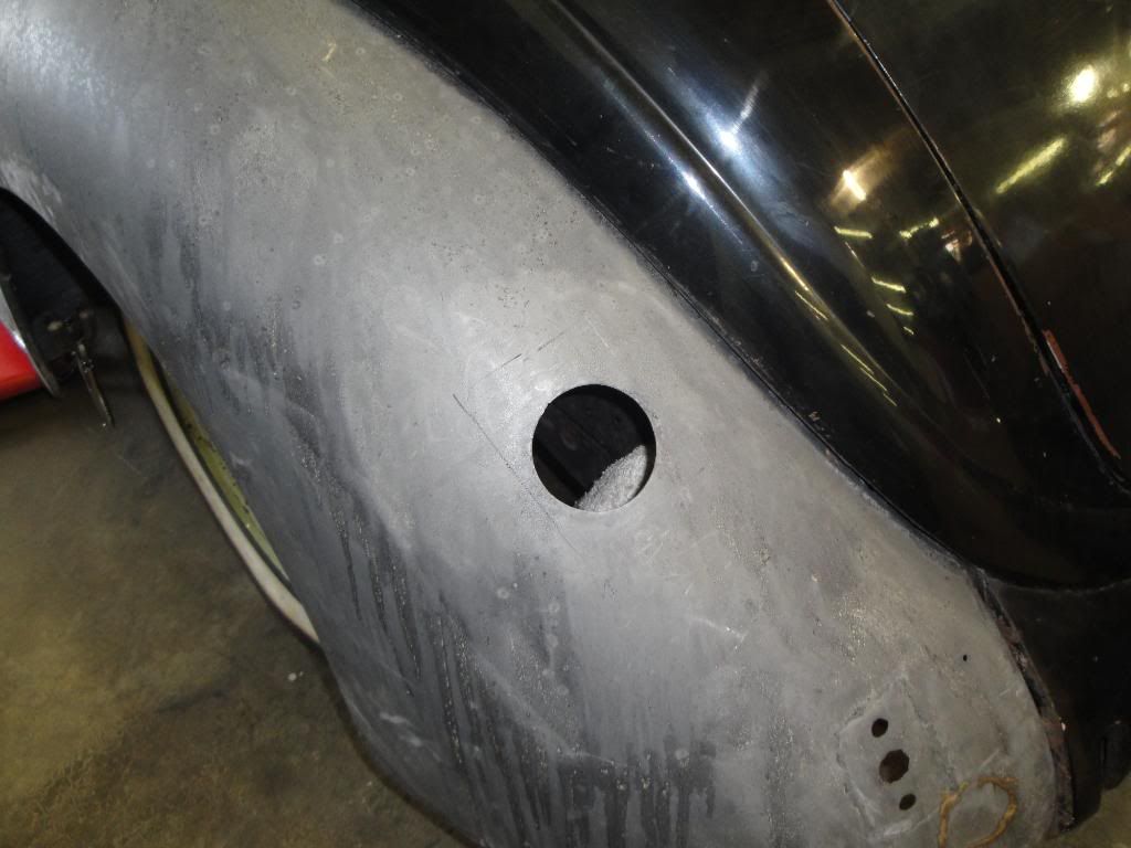
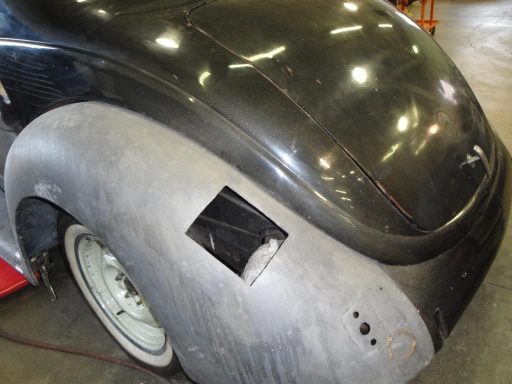
Todays project........Make the gas Cap on the fender go away....
Starting Point.........
Cap assy removed
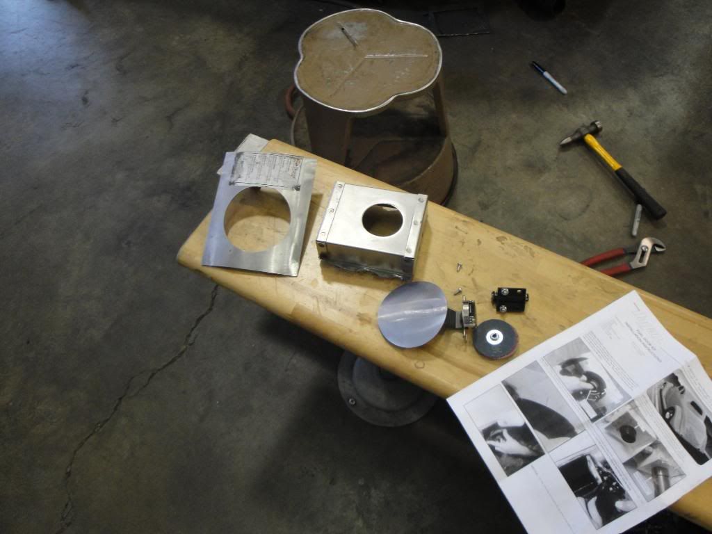
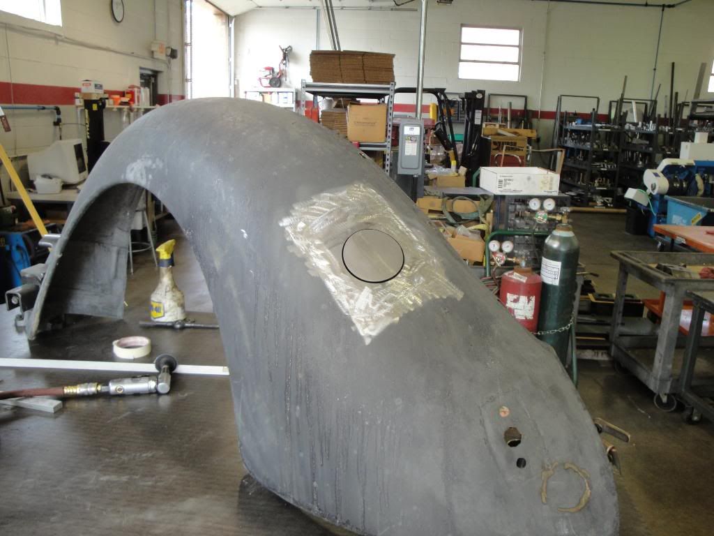
Hagen Gas Door assy.....Had to cut it apart to get the fender portion to match the fender profile
Cut the opening in the fender
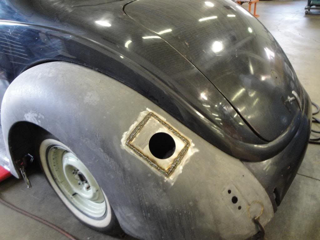
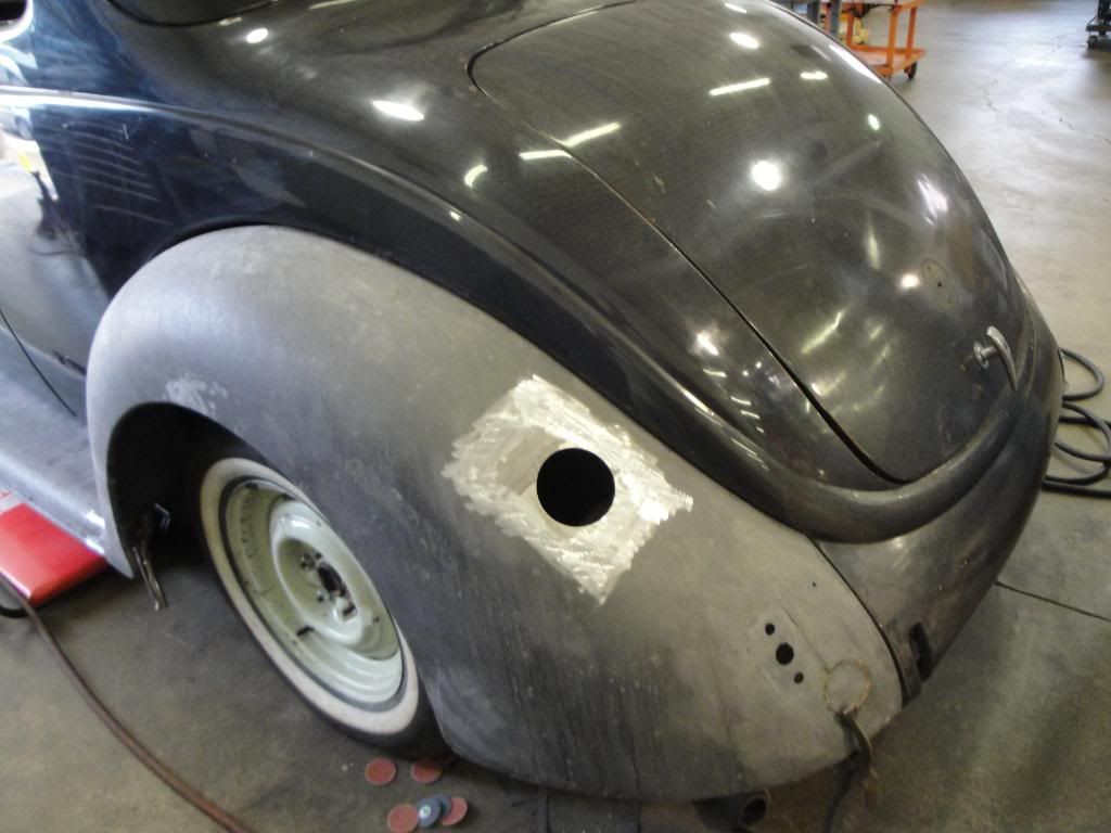
New Insert profiled and welded in......
Gas door assy installed......the gas cap has the flapper for the fill nozzle (Don't have to take the cap off while filling).....Also has a Magnetic stop pin and lifter....Pretty Cool......

Ken
Starting Point.........
Cap assy removed
Hagen Gas Door assy.....Had to cut it apart to get the fender portion to match the fender profile
Cut the opening in the fender
New Insert profiled and welded in......
Gas door assy installed......the gas cap has the flapper for the fill nozzle (Don't have to take the cap off while filling).....Also has a Magnetic stop pin and lifter....Pretty Cool......
Ken
Thread Starter
TECH Fanatic
Joined: Jul 2008
Posts: 1,570
Likes: 173
Does anyone know if there are any aftermarket fittings available for both the Fuel Rail and the fuel pump for the fuel line...(Both 2006 LS2 GTO).....It seems that the GTO set-up is a single line feed.......or am I looking at this wrong??
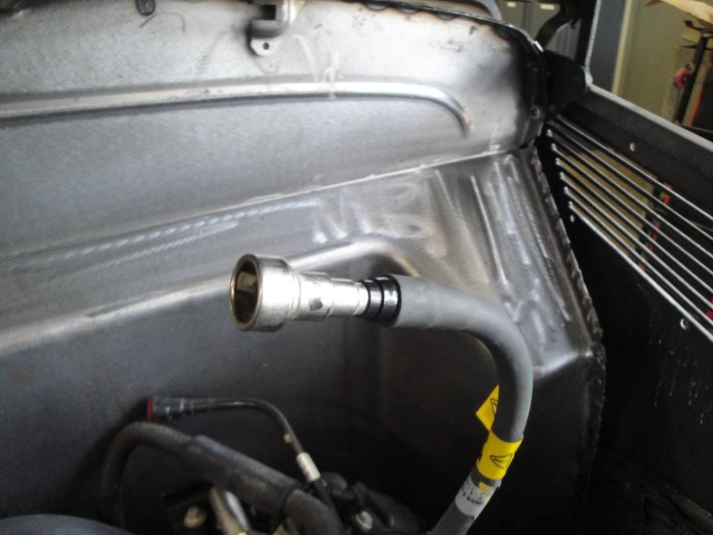
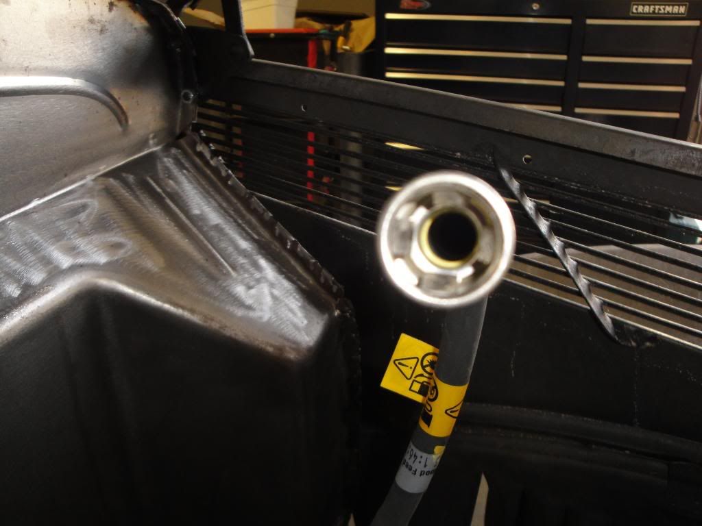
Fuel Pump.........
Thanks
Ken
Fuel Pump.........
Thanks
Ken