

'70 Nova LY6/TH400 6.0VVT


 10-23-2015, 01:09 PM
#1022
Happy to report the fuel pump is finally at home in the tank. I ran into a few challenges getting this done though. Despite the mounting position being pretty well centered over the deepest part of the tank, the v-shape of the bottom of the tank prevented the rectangular shaped mini-sump/tray from sitting flat against the bottom. This was especially problematic because the overall height of the tank is barely enough to fit the pump into. There was also interference with the float on the sending unit, so I modified things to offset the mini-sump/tray so that one edge and the pump itself can sit in the bottom vee of the tank and the sending unit float can move unhindered outside of the tray.
Here is the now-offset module assembled:


I applied a thin layer of Permatex #2 non-hardening sealer on both sides of the cork gasket and the screw threads before installing. Then once everything was assembled, I sprayed the welds, screws, and fittings with soapy water and pressurized the tank to look for bubbles - no leaks. I painted the raw metal with some leftover hammer-finish rustoleum and it's pretty much ready to go in now.

I need to run the vent line and cap the sending unit, then I can mount this under the car and connect it to the filter/regulator. That will complete the fuel system and I'll be ready to move to another system.
I spent some time thinking about my strategy for getting the car running. I'm now working around the following project plan and will focus on one area at a time rather than bouncing around like I have been in the past:
(1) Fuel System: tank/pump, plumbing to FPR, pigtail wiring
(2) High amp electrical: Mount battery, cutout switch, power distribution, fan relays, plug wires
(3) Low amp electrical: logic/signal level wiring, gauges
(4) Plumbing: radiator hoses, transmission cooling lines, steam, PCV, filter
(5) Programming: ECM programming/base tune
Here is the now-offset module assembled:
I applied a thin layer of Permatex #2 non-hardening sealer on both sides of the cork gasket and the screw threads before installing. Then once everything was assembled, I sprayed the welds, screws, and fittings with soapy water and pressurized the tank to look for bubbles - no leaks. I painted the raw metal with some leftover hammer-finish rustoleum and it's pretty much ready to go in now.
I need to run the vent line and cap the sending unit, then I can mount this under the car and connect it to the filter/regulator. That will complete the fuel system and I'll be ready to move to another system.
I spent some time thinking about my strategy for getting the car running. I'm now working around the following project plan and will focus on one area at a time rather than bouncing around like I have been in the past:
(1) Fuel System: tank/pump, plumbing to FPR, pigtail wiring
(2) High amp electrical: Mount battery, cutout switch, power distribution, fan relays, plug wires
(3) Low amp electrical: logic/signal level wiring, gauges
(4) Plumbing: radiator hoses, transmission cooling lines, steam, PCV, filter
(5) Programming: ECM programming/base tune
10-23-2015, 05:00 PM
#1024
Thanks Joe. I have a rollover valve built into the pump module with a barb fitting. I plan to run a hose from there to a filter near the back bumper area, somewhere higher than the tank, for venting. I currently have a vented gas cap too; I may want to cap one or the other depending on how things work out. I don't remember the vented gap giving me any issues before so I'm currently undecided.
10-26-2015, 10:38 AM
#1025
I got a few more hours into the car yesterday and buttoned up the fuel system. The tank is finally strapped under the car and I'm 100% connected from in-tank pump to the fuel injectors.

Here is a look at the clearance where the fuel pump fittings exit the top of the tank - pretty much right up against the trunk floor.

And to prove things are plumbed, here is a photo of the filter/regulator.

I mounted it to the frame by drilling and a tapping a 1/4-20 hole. The filter/regulator is a Wix 33737 for a '99-'04 Corvette. I used Fragola -6 braided nylon hose with Russel fittings for the supply and return lines. On the tank end, I used 1/4NPT to -6 JIS flare fittings from a hydraulic supply then Russel 610025 -6 AN to -6 hose ends. For the filter end, I used Russel 611253 and 611203 ends which go directly from -6 hose to the 5/16 and 3/8 push-connect fittings on the regulator (I used the same 611203 at fuel rail). I used Russel 640940 to connect from the regulator outlet to -6 flare for the 3/8" hard line going to the front of the car. My quick add on fuel line and fittings (not including the filter/regulator) is around $200 from tank to fuel rail. The Russel fittings that go directly from hose to EFI push-connect were ~$70 of that ($23ea), the braided hose about $64, and a 25' roll of 3/8" steel line was $30. There are cheaper ways to plumb this to be sure, but I like the AN fittings and braided hose.
Adding up costs on the fuel system, I am just floored at what I've spent on the fuel system. $200 in fittings/hoses, $35 filter/regulator, $315 for the Walbro 255 pump Tanks Inc. hanger rollover valve and prefabbed recess tray, $200 for welding, $160 for a new tank. That's over $900. My original plan was to use my original tank ($-160) and just cut a hole in the trunk and make a cover myself rather than recess the pump hanger ($-245), which would have saved about $400. These days you can get a ready made fuel injection tank for this application from Tanks Inc for $255 plus the cost of a pump and hanger - I would definitely go that route if I had to do this over again.
Here is a look at the clearance where the fuel pump fittings exit the top of the tank - pretty much right up against the trunk floor.
And to prove things are plumbed, here is a photo of the filter/regulator.
I mounted it to the frame by drilling and a tapping a 1/4-20 hole. The filter/regulator is a Wix 33737 for a '99-'04 Corvette. I used Fragola -6 braided nylon hose with Russel fittings for the supply and return lines. On the tank end, I used 1/4NPT to -6 JIS flare fittings from a hydraulic supply then Russel 610025 -6 AN to -6 hose ends. For the filter end, I used Russel 611253 and 611203 ends which go directly from -6 hose to the 5/16 and 3/8 push-connect fittings on the regulator (I used the same 611203 at fuel rail). I used Russel 640940 to connect from the regulator outlet to -6 flare for the 3/8" hard line going to the front of the car. My quick add on fuel line and fittings (not including the filter/regulator) is around $200 from tank to fuel rail. The Russel fittings that go directly from hose to EFI push-connect were ~$70 of that ($23ea), the braided hose about $64, and a 25' roll of 3/8" steel line was $30. There are cheaper ways to plumb this to be sure, but I like the AN fittings and braided hose.
Adding up costs on the fuel system, I am just floored at what I've spent on the fuel system. $200 in fittings/hoses, $35 filter/regulator, $315 for the Walbro 255 pump Tanks Inc. hanger rollover valve and prefabbed recess tray, $200 for welding, $160 for a new tank. That's over $900. My original plan was to use my original tank ($-160) and just cut a hole in the trunk and make a cover myself rather than recess the pump hanger ($-245), which would have saved about $400. These days you can get a ready made fuel injection tank for this application from Tanks Inc for $255 plus the cost of a pump and hanger - I would definitely go that route if I had to do this over again.
Last edited by -TheBandit-; 10-26-2015 at 11:00 AM.
11-13-2015, 12:17 PM
#1027
Agreed, fuel systems get expensive in a hurry! I did all my own work and re-used my original tank and still have >$300 wrapped up in the fuel feed system!
Any progress updates? I said I'd be stopping in and bugging you and I meant it! #Banditbyspring16
Oh ya I #'d it
Any progress updates? I said I'd be stopping in and bugging you and I meant it! #Banditbyspring16
Oh ya I #'d it
11-13-2015, 01:16 PM
#1028
Oh no there's a hashtag now... hahaha!
All I've done in the last three weeks is mount the old battery in the trunk. I am using a Moroso 74051 sealed poly box which meets both NHRA and SCCA requirements for a trunk-related battery.

Putting this in was just a matter of locating and drilling two holes, so it's not exactly stellar progress. Now I am debating how I want to mount the disconnect switch. I bought a push-pull mechanism thinking it might be nice to take off the rod when I'm not using it, but I also like the simplicity of mounting the switch directly to the tail panel.
Here is where I plan to either have the switch or the push-pull rod protruding with examples of each.


The push-pull photo just above is what spurred me to buy the mechanism.
Pros: exterior aesthetics, actuation, removable rod, less likely to arc in a rear end collision, may automatically get pushed off in a rear collision
Cons: more complicated to mount, takes up space in the trunk, actuation may not work in a rear collision
Any opinions on which way I should go?
All I've done in the last three weeks is mount the old battery in the trunk. I am using a Moroso 74051 sealed poly box which meets both NHRA and SCCA requirements for a trunk-related battery.
Putting this in was just a matter of locating and drilling two holes, so it's not exactly stellar progress. Now I am debating how I want to mount the disconnect switch. I bought a push-pull mechanism thinking it might be nice to take off the rod when I'm not using it, but I also like the simplicity of mounting the switch directly to the tail panel.
Here is where I plan to either have the switch or the push-pull rod protruding with examples of each.
The push-pull photo just above is what spurred me to buy the mechanism.
Pros: exterior aesthetics, actuation, removable rod, less likely to arc in a rear end collision, may automatically get pushed off in a rear collision
Cons: more complicated to mount, takes up space in the trunk, actuation may not work in a rear collision
Any opinions on which way I should go?
Last edited by -TheBandit-; 11-13-2015 at 01:49 PM.
11-13-2015, 02:16 PM
#1029
I like the push-pull option, and I'd swap out my rotary switch for one if given the opportunity. I also ran mine through the tail light because I'm not a fan of drilling the body (especially in that location), and installed a 250 amp fuse between the battery and the switch.
And I feel you on the tank costs. I'm strongly considering the Tanks Inc setup, using my Aeromotive pump. I've read that it does well on the autocross, even low on fuel. With my current setup, I start sweating bullets when that gas gauge nears 1/4 tank. And sadly, my pump module doesn't allow me to run a return line near the pump in its current configuration.
And I feel you on the tank costs. I'm strongly considering the Tanks Inc setup, using my Aeromotive pump. I've read that it does well on the autocross, even low on fuel. With my current setup, I start sweating bullets when that gas gauge nears 1/4 tank. And sadly, my pump module doesn't allow me to run a return line near the pump in its current configuration.
Last edited by hookemdevils22; 11-13-2015 at 03:54 PM.
11-16-2015, 11:13 AM
#1030
Okay I have decided to go the push-pull route, because I think it looks better than a rotary type and I'll have the option to take out the rod when I'm not at at the track (99.9% of the time). I am using a Jegs 10370 push-pull assembly and QuickCar 55-011 master disconnect switch. This switch has separate terminals to isolate the alternator, preventing the engine from running off alternator power so it can truly be shut off.
Looking over options, I decided I would like to mount this right behind the tail panel on the "shelf" that exists in the trunk. I began by placing the switch assembly in this area to mark the height/position for the thru hole, using a predetermined distance from the taillight for left-right placement.

Then I drilled a pilot hole from the inside of the trunk. I hope I don't regret this down the road.

Next I opened up the hole until I could just fit the rod through. The mock-up is looking good.

The Jegs kit comes with a 5/8" ID grommet while the rod is 1/2" OD. The fit is just too loose for my liking so I will pick up a new grommet today, final size the hole, and move on to mounting the bracket and resizing the rod.
Looking over options, I decided I would like to mount this right behind the tail panel on the "shelf" that exists in the trunk. I began by placing the switch assembly in this area to mark the height/position for the thru hole, using a predetermined distance from the taillight for left-right placement.
Then I drilled a pilot hole from the inside of the trunk. I hope I don't regret this down the road.
Next I opened up the hole until I could just fit the rod through. The mock-up is looking good.
The Jegs kit comes with a 5/8" ID grommet while the rod is 1/2" OD. The fit is just too loose for my liking so I will pick up a new grommet today, final size the hole, and move on to mounting the bracket and resizing the rod.
Last edited by -TheBandit-; 11-16-2015 at 11:42 AM.
11-19-2015, 04:48 PM
#1031
As luck would have it, a snug fitting grommet resulted in a lot of binding, so I ended up opening the tailpanel hole to use the 5/8" ID grommet already supplied with the Jeg's push-pull assembly. The resulting mechanism works well, but is definitely not water tight. Below is a photo of it mounted; the light coming through the hole makes it look like a bigger gap that it is; there is 1/8" difference between the grommet ID and rod OD.

I've been wanting to get my son involved in the build and shortening the actuation rod was a perfect opportunity. We cut it down on the band saw then we put it into a little 3-jaw chuck to keep it reasonably square on the drill press. He helped me drill the hole and tap it for 1/4-20.

Then I had him assemble the rod into the switch and test it out. Mission accomplished!


I'm happy with how it turned out. Now I need to get the bumper back on and order the wiring components.
I've been wanting to get my son involved in the build and shortening the actuation rod was a perfect opportunity. We cut it down on the band saw then we put it into a little 3-jaw chuck to keep it reasonably square on the drill press. He helped me drill the hole and tap it for 1/4-20.
Then I had him assemble the rod into the switch and test it out. Mission accomplished!
I'm happy with how it turned out. Now I need to get the bumper back on and order the wiring components.
11-21-2015, 06:30 PM
#1033
Today I cut a piece of copper pipe

Then I hammered it flat

Next I bent it in a vice, drilled a couple holes, and rounded the corners.

Finally I installed it - buss bar for the master disconnect switch.

Then I hammered it flat
Next I bent it in a vice, drilled a couple holes, and rounded the corners.
Finally I installed it - buss bar for the master disconnect switch.
Last edited by -TheBandit-; 11-21-2015 at 07:30 PM.
12-03-2015, 05:27 PM
#1035
Thanks Wayne!
I am gathering wiring components to accomplish my next goal of wiring from the battery to the fuse center so I can move on to more signal-level engine wiring. Before the work starts, I'd like to share my electrical design and see if anyone has feedback one way or another.
Here are the basic requirements:
(1) Reliably supply current to all required components with minimal voltage loss
(2) Meet NHRA requirements for master disconnect ("This cutoff switch must be connected to the positive side of the electrical system and must stop all electrical functions, including magneto ignition.")
(4) Be tidy and serviceable
Master disconnect wiring was a topic of interest for me. There are three conventional ways of accomplishing this:
Unfortunately for me, method 3 only works if you have access to the field wire for the alternator. On Gen IV LSxs, the alternator has an internal voltage regulator and PWM-commanded voltage. The PWM functionality relies on a couple of things I am not implementing for my swap (specifically a body control module and a battery current sensing module); without those components the alternator defaults to an output of 13.8v and behaves like a 1-wire alternator. There is no way to separate the field input from the charge wire. The 13.8v is not ideal for supplying the car, but that's what the alternator puts out as default when it's not supplied with a PWM signal.
I am not very keen on running a bunch of heavy gauge wire front to back of my car and I want to make sure the full regulated voltage is available from the alternator to supply the vehicle, so I've come up with an alternate method which I've diagrammed below (note I have omitted fuses from the diagram). This method uses the power turn on relay that supplies dedicated power to the ignition coils, injectors and other engine components as a means of stopping the engine (therefore alternator charging) when the disconnect is opened.

Starting at the bottom of the diagram, the battery will be grounded locally to the formed frame-rail area using a bumper attachment bolt. I know some people run dedicated, heavy gauge grounds to the front of the vehicle subframe or engine, but I will rely on strapping and the body as a conductor (as many OEMs do).
The positive battery terminal will go to the disconnect switch and will be bussed to supply power to both poles of the switch. The high current side of the switch will run via 1/0 welding cable to the front, passenger side of the car where I will install a jump-start terminal. From there, 1/0 welding cable will supply the starter and 4awg welding cable will supply the main power junction at the horn relay on the driver's side of the car. The alternator charge line will be connected to the main power junction, which should keep this point regulated very close to 13.8v. This is very similar to how a 2010+ Camaro is wired from the factory, except they use the jump start terminal as the main junction and it is located on the driver's side.
The interesting part is on the low current side of the disconnect switch. This will be used to supply isolated power to the fuel pump (via a relay) and signal level power for the power turn on relay at the front of the car. Most "5-wire" harnesses for these engines eliminate the power turn on relay and simply power these components directly from the ignition switch, key-on position. By keeping this relay and supplying it with isolated power from the disconnect switch, I am able to use the disconnect switch to kill ignition and fuel supply to the engine, independently of the alternator charge line. This should stop engine function and result in dead wires everywhere except the battery itself and a short length of cable leading to the disconnect switch.
End result will be 2 small gauge (probably 18awg) wires running to the front of the car to run relays and one heavy gauge wire to the front of the car to run vehicle including the starter and to charge the battery during normal use.
At this point I think everything will work as diagrammed, but I am open to input. The only change I am seriously considering at the moment is putting the fuel pump on the heavy gauge output side of the disconnect rather than the same side as the power turn on relay. This would give something to sink alternator current in the brief period that the engine turns without ignition.
I am gathering wiring components to accomplish my next goal of wiring from the battery to the fuse center so I can move on to more signal-level engine wiring. Before the work starts, I'd like to share my electrical design and see if anyone has feedback one way or another.
Here are the basic requirements:
(1) Reliably supply current to all required components with minimal voltage loss
(2) Meet NHRA requirements for master disconnect ("This cutoff switch must be connected to the positive side of the electrical system and must stop all electrical functions, including magneto ignition.")
(4) Be tidy and serviceable
Master disconnect wiring was a topic of interest for me. There are three conventional ways of accomplishing this:
- Method 1: Run a STSP (single throw, single pole) disconnect switch and run on dedicated, heavy gauge charge wire from battery positive terminal to the alternator and a separate heavy gauge wire from the disconnect switch to the rest of the vehicle. When the switch is opened, the alternator can charge the battery, but can't keep the engine running so everything shuts down. There are two disadvantages to this method: (1) the heavy gauge alternator cable is kept hot by the battery even with the switch is open and (2) it requires two heavy gauge wires to the back of the car.
- Method 2: Run a STDP (single throw, double pole) disconnect switch. For one pole, run a heavy gauge wire to the starter and rest of the vehicle. For the other pole, run a heavy gauge wire to the alternator charge wire. Compared to method 1, this has the advantage of eliminating a hot wire to the front of the vehicle, but still requires two heavy gauge wires and violates the current limitations for most STDP disconnect switches where the second pole is typically only rated to around 20amps.
- Method 3: My favorite of the conventional wiring methods is this method. You run a STDP disconnect switch. For one pole, you run heavy gauge wire to the starte, alternator charge line and the rest of the vehicle. You run the other pole in series with the alternator field wire. This allow use of a light gauge wire because the field line for the alternator is relatively low current. When the switch is open, no wires are hot forward of the battery/disconnect area.
Unfortunately for me, method 3 only works if you have access to the field wire for the alternator. On Gen IV LSxs, the alternator has an internal voltage regulator and PWM-commanded voltage. The PWM functionality relies on a couple of things I am not implementing for my swap (specifically a body control module and a battery current sensing module); without those components the alternator defaults to an output of 13.8v and behaves like a 1-wire alternator. There is no way to separate the field input from the charge wire. The 13.8v is not ideal for supplying the car, but that's what the alternator puts out as default when it's not supplied with a PWM signal.
I am not very keen on running a bunch of heavy gauge wire front to back of my car and I want to make sure the full regulated voltage is available from the alternator to supply the vehicle, so I've come up with an alternate method which I've diagrammed below (note I have omitted fuses from the diagram). This method uses the power turn on relay that supplies dedicated power to the ignition coils, injectors and other engine components as a means of stopping the engine (therefore alternator charging) when the disconnect is opened.
Starting at the bottom of the diagram, the battery will be grounded locally to the formed frame-rail area using a bumper attachment bolt. I know some people run dedicated, heavy gauge grounds to the front of the vehicle subframe or engine, but I will rely on strapping and the body as a conductor (as many OEMs do).
The positive battery terminal will go to the disconnect switch and will be bussed to supply power to both poles of the switch. The high current side of the switch will run via 1/0 welding cable to the front, passenger side of the car where I will install a jump-start terminal. From there, 1/0 welding cable will supply the starter and 4awg welding cable will supply the main power junction at the horn relay on the driver's side of the car. The alternator charge line will be connected to the main power junction, which should keep this point regulated very close to 13.8v. This is very similar to how a 2010+ Camaro is wired from the factory, except they use the jump start terminal as the main junction and it is located on the driver's side.
The interesting part is on the low current side of the disconnect switch. This will be used to supply isolated power to the fuel pump (via a relay) and signal level power for the power turn on relay at the front of the car. Most "5-wire" harnesses for these engines eliminate the power turn on relay and simply power these components directly from the ignition switch, key-on position. By keeping this relay and supplying it with isolated power from the disconnect switch, I am able to use the disconnect switch to kill ignition and fuel supply to the engine, independently of the alternator charge line. This should stop engine function and result in dead wires everywhere except the battery itself and a short length of cable leading to the disconnect switch.
End result will be 2 small gauge (probably 18awg) wires running to the front of the car to run relays and one heavy gauge wire to the front of the car to run vehicle including the starter and to charge the battery during normal use.
At this point I think everything will work as diagrammed, but I am open to input. The only change I am seriously considering at the moment is putting the fuel pump on the heavy gauge output side of the disconnect rather than the same side as the power turn on relay. This would give something to sink alternator current in the brief period that the engine turns without ignition.
12-15-2015, 11:34 AM
#1036
UPS dropped off wire, terminals, and a new tool - a hydraulic hex crimper. This is a Chinese model but not the one from Harbor Freight. The HF version has poorly sized dies from what I've read, so I picked up this "TMS 16 ton hydraulic crimper" from an Amazon seller. It's labeled "YQK-300" and cost about $40.
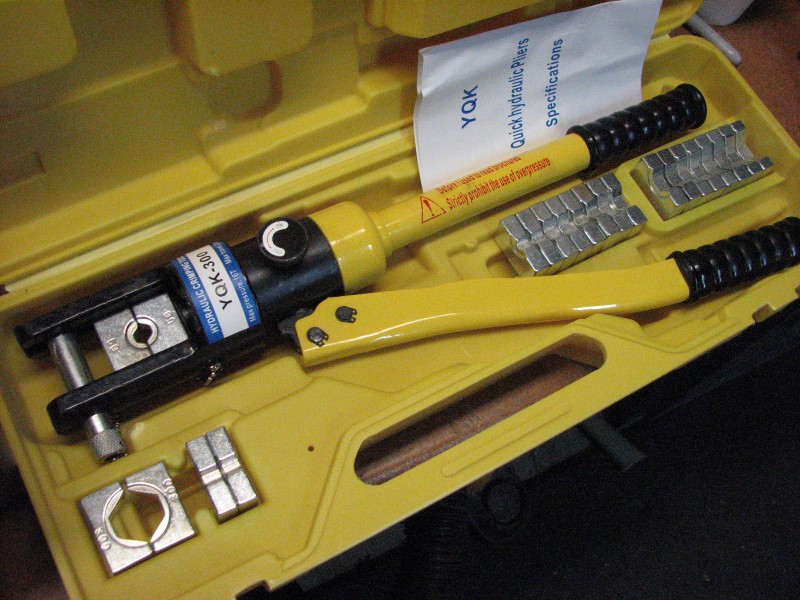
I gave it a try on 4awg using a 25mm^2 hex die and it seemed to work pretty well. I did have to do the crimp twice, rotating the dies on the second pass to flatten out a small amount of pinch/squeeze-out that happened on the first pass.


Next I tried it on the 1/0awg using a 50mm^2 hex die. I used the same two-pass, rotate method and it seemed to do the trick.


I think this is going to do nicely. Now I just need to get to work.
I gave it a try on 4awg using a 25mm^2 hex die and it seemed to work pretty well. I did have to do the crimp twice, rotating the dies on the second pass to flatten out a small amount of pinch/squeeze-out that happened on the first pass.
Next I tried it on the 1/0awg using a 50mm^2 hex die. I used the same two-pass, rotate method and it seemed to do the trick.
I think this is going to do nicely. Now I just need to get to work.
12-15-2015, 01:24 PM
#1037
Just make sure your ECM stays hot when you kill the battery. It is going to cause you cold start, part throttle driving problems until the ECM "relearns" where it's at under driving conditions. It is not a good idea to connect/disconnect/connect the ECM repeatedly...
With regards to your crimps. Move the die out to the end and crimp away the flare at the end of the lug, You want to maximize contact surface on crimped connections....
T,
With regards to your crimps. Move the die out to the end and crimp away the flare at the end of the lug, You want to maximize contact surface on crimped connections....
T,
12-15-2015, 03:28 PM
#1039
Tom - Thanks for the advice. I'll consider running an "always hot" from the battery to ECM X1-20 B+. I don't expect to use the disconnect much but it would suck for the ECM to have to relearn after a tech inspector tests the system prior to a run.
Joe - Your tool collection needs a quad-point, dieless crimper like this one. Those are more awesome and only about 5-10 times the cost. Just think - if you do a dozen crimps in your lifetime, they will only cost about $300 per crimp + opportunity costs.
Joe - Your tool collection needs a quad-point, dieless crimper like this one. Those are more awesome and only about 5-10 times the cost. Just think - if you do a dozen crimps in your lifetime, they will only cost about $300 per crimp + opportunity costs.
12-15-2015, 04:06 PM
#1040
Tom - Thanks for the advice. I'll consider running an "always hot" from the battery to ECM X1-20 B+. I don't expect to use the disconnect much but it would suck for the ECM to have to relearn after a tech inspector tests the system prior to a run.
Joe - Your tool collection needs a quad-point, dieless crimper like this one. Those are more awesome and only about 5-10 times the cost. Just think - if you do a dozen crimps in your lifetime, they will only cost about $300 per crimp + opportunity costs.
Joe - Your tool collection needs a quad-point, dieless crimper like this one. Those are more awesome and only about 5-10 times the cost. Just think - if you do a dozen crimps in your lifetime, they will only cost about $300 per crimp + opportunity costs.