
I want a build thread too....'63 Chevy II Wagon.


 07-06-2011, 05:27 PM
#122

The beginnings of the exhaust system laid out on a piece of sheetrock..the only thing I had large enough to trace it out on. Plus its fire resistant so I just tacked it all together as it sits. 
Its a Summit 2.5 x-pipe into some chambered mufflers, probably flowmaster knockoffs, the price was right. Tailpipes are TBD.


The mufflers will get moved farther back and I wont be using these sweet muffler hangers.

Its a Summit 2.5 x-pipe into some chambered mufflers, probably flowmaster knockoffs, the price was right. Tailpipes are TBD.
The mufflers will get moved farther back and I wont be using these sweet muffler hangers.
07-21-2011, 10:22 PM
#123
PS rack is back in for the second or third time, and I think this is the last time!
The lines turned out OK. Where they meet the fittings is nice and square, no tension on the lines to get the flares to line up, but they could be tucked up a little more and run a little tighter together. But Im calling it DONE. Fired it up, cranked it lock to lock and no leaks yet.


Over the winter I may take the lines off and send them out to be copied if there is sufficient interest in marketing these. The only part of them I haven't sourced is the tube nuts at the center of the rack. Does a metric 45� flare nut even exist?
Also, this weekend the '58 Olds goes home so I get 60% of the garage back. The wagon will get moved over and the exhaust will get hung and the shifter will get figured out.
Then it should be able to be driven, finally
The lines turned out OK. Where they meet the fittings is nice and square, no tension on the lines to get the flares to line up, but they could be tucked up a little more and run a little tighter together. But Im calling it DONE. Fired it up, cranked it lock to lock and no leaks yet.
Over the winter I may take the lines off and send them out to be copied if there is sufficient interest in marketing these. The only part of them I haven't sourced is the tube nuts at the center of the rack. Does a metric 45� flare nut even exist?
Also, this weekend the '58 Olds goes home so I get 60% of the garage back. The wagon will get moved over and the exhaust will get hung and the shifter will get figured out.
Then it should be able to be driven, finally
07-28-2011, 03:39 PM
#124
Finishing up the majority of the exhaust today...all that's left is the rear hangers.
Started with welding up the pipes that go into the x. It's ok to weld on a wooden work bench, isn't it? Mig is quick and easy...but...slag city Past experience has shown me I'm really good at burning through thin materials with a mig, so I like doing the overlapping circular welds.


Aside from using several levels and body points as reference, I ran a guide string across the rockers...just tied some washers on the ends and dropped them inside the car through the windows. Simple enough.


And rather than build some kind of support to get the mufflers at the right height...I dug into my secret stash of tools and came up with the recycling bin. The trashman came today so it worked out pretty well It was within 1" of being the right height so what the heck. Plus it was wide enough to support both at the same time. Fine tuning was done with some plywood and builder's shims since the garage floor isnt level anyway. What a handy tool, I think I'll keep it.


For the record, I hate doing exhaust work. It's rarely easy..and the slip joints usually dont slip too well. I do like the flat 3" wide band clamps when the pipes butt together...much easier to work with than a slip joint. For this system I used 4 band clamps so that it can be taken apart in sections by one person...hopefully without much struggle.
Started with welding up the pipes that go into the x. It's ok to weld on a wooden work bench, isn't it? Mig is quick and easy...but...slag city
Past experience has shown me I'm really good at burning through thin materials with a mig, so I like doing the overlapping circular welds.Aside from using several levels and body points as reference, I ran a guide string across the rockers...just tied some washers on the ends and dropped them inside the car through the windows. Simple enough.
And rather than build some kind of support to get the mufflers at the right height...I dug into my secret stash of tools and came up with the recycling bin. The trashman came today so it worked out pretty well
It was within 1" of being the right height so what the heck. Plus it was wide enough to support both at the same time. Fine tuning was done with some plywood and builder's shims since the garage floor isnt level anyway. What a handy tool, I think I'll keep it.For the record, I hate doing exhaust work. It's rarely easy..and the slip joints usually dont slip too well. I do like the flat 3" wide band clamps when the pipes butt together...much easier to work with than a slip joint. For this system I used 4 band clamps so that it can be taken apart in sections by one person...hopefully without much struggle.
07-28-2011, 09:56 PM
#125
Almost the final pictures  The last step will be taking it all off, scuffing it, and painting it with the same Cast Blast I used on the PS rack.
No jacks or recycling bins


From the edge of the muffler outlets to the inside of the leaf springs is 9 7/8" on each side...didnt think it would be right on, I figured maybe within 1/4" so Im happy to see that. The mufflers can still be moved about 2" closer to the floor, but I dont want to tuck them up too far until the over-the-axle pipes are figured out.
The next system will be made entirely of non-aluminized mild steel. So much nicer to weld.
This is my sweet drafting table for figuring out the pipe angles. Just have to make due with what's available. Plus it will be an ok story in 10 years haha.

The last step will be taking it all off, scuffing it, and painting it with the same Cast Blast I used on the PS rack.No jacks or recycling bins
From the edge of the muffler outlets to the inside of the leaf springs is 9 7/8" on each side...didnt think it would be right on, I figured maybe within 1/4" so Im happy to see that. The mufflers can still be moved about 2" closer to the floor, but I dont want to tuck them up too far until the over-the-axle pipes are figured out.
The next system will be made entirely of non-aluminized mild steel. So much nicer to weld.
This is my sweet drafting table for figuring out the pipe angles. Just have to make due with what's available. Plus it will be an ok story in 10 years
08-11-2011, 03:23 PM
#126
Spent some time yesterday between work shifts putting the sheathing on part of the wiring harness. Not a fun job and it could be better. To me it's as close to a factory look as I think it will get, but eventually I want to make a second harness and do this all over again.


 08-11-2011, 03:24 PM
#128
Here's what I'm thinking for the rear pcv line. I dont have much room between the throttle arm and the back of the intake to fit the stock tube. I don't really see an issue connecting the dr side to the passenger side and then pulling all the vacuum through the front pcv port on the pass valvecover. That's basically how GM did it anyway. The port on the side of the intake by the tb would be plugged off.


I think it will be ok. Hopefull the line will relax once it gets warm so it lays down and blends in better :yes:
I think it will be ok. Hopefull the line will relax once it gets warm so it lays down and blends in better :yes:


 08-14-2011, 09:41 PM
#131
Finished the throttle cable tonight. I also put the stock mcv hoses on and routed them differently to avoid the throttle arm.


For now, everything under the hood is done, until winter when I redo a few things. All that is left is the shifter linkage and putting the front seat back in.
I also found out tonight that the transmission transmits I started it in gear with my foot on the brake, then let it idle with my foot off the brake, then gave it a little gas until it shifted into 2nd. It was a good night. Another week and it should be on the road...FINALLY!
For now, everything under the hood is done, until winter when I redo a few things. All that is left is the shifter linkage and putting the front seat back in.
I also found out tonight that the transmission transmits
I started it in gear with my foot on the brake, then let it idle with my foot off the brake, then gave it a little gas until it shifted into 2nd. It was a good night. Another week and it should be on the road...FINALLY!
08-15-2011, 08:52 AM
#132

Everything looks great.. congrats!
09-12-2011, 11:40 AM
#135
For the past few weeks I've been building a shift linkage...starting with this

To get technical about it, these are angle diagrams of the gear detents in the column and the detents of the transmission prawl. If the column and trans detent angles were exactly the same, then you could simply make the shift arm on the end of the column the same length as the transmission lever and connect the two with a cable or linkage. But the problem is the angles aren't the same. It may work, but it wouldn't be precise and I didn't want to go that route. The actual linear movement of the shift cable (or linkage arm) needs to be calculated, which is easy to do, and then work backwards to the column lever to get the correct placement (length and initial degree) of the column arm. Ok...lets go back to pictures.
This was a quick mock up of the column arm and linkage rod...some 6061 aluminum rod, threaded, with a rod end on each end that will go to a bell crank.


Making a template using the original steering box holes so that no new holes need to be drilled...

Pretty much all the parts needed except for the cable itself...

Here's all that's seen on the outside...


And here's it all installed...

To get technical about it, these are angle diagrams of the gear detents in the column and the detents of the transmission prawl. If the column and trans detent angles were exactly the same, then you could simply make the shift arm on the end of the column the same length as the transmission lever and connect the two with a cable or linkage. But the problem is the angles aren't the same. It may work, but it wouldn't be precise and I didn't want to go that route. The actual linear movement of the shift cable (or linkage arm) needs to be calculated, which is easy to do, and then work backwards to the column lever to get the correct placement (length and initial degree) of the column arm. Ok...lets go back to pictures.
This was a quick mock up of the column arm and linkage rod...some 6061 aluminum rod, threaded, with a rod end on each end that will go to a bell crank.
Making a template using the original steering box holes so that no new holes need to be drilled...
Pretty much all the parts needed except for the cable itself...
Here's all that's seen on the outside...
And here's it all installed...
09-12-2011, 11:41 AM
#136
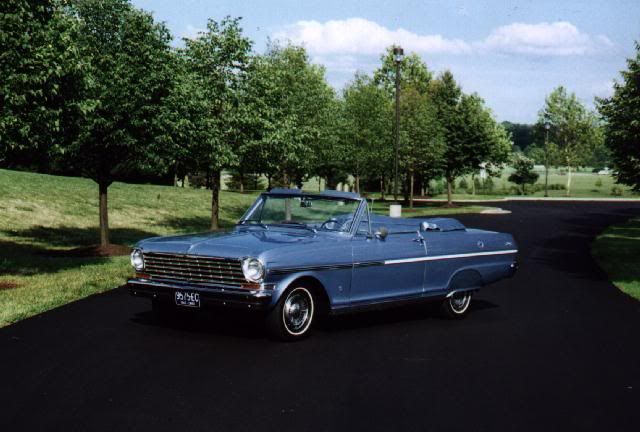
Finally.....after 12 1/2 months of hibernation, she sees the sun again, albeit topless. The first time I took it around the neighborhood, some guy in his driveway yelled "Light 'em up!". Dude, this is a station wagon...c'mon.


I've put about 100 miles on it so far and it hasn't missed a beat. The shifter and fuel tank thing work correctly, the fuel gauge works like a stock gauge does, and the water temps stay at or below 190 unless it sits and idles for a long time (10 mins). I took it out on the highway for 75-80 miles and Fan 1 never came on. The converter locks and unlocks as it should and the aftermarket suspension rides nice, it's not jarring and there were a few bumps in the highway I was bracing for that it took much better than I thought it would.
I have to do something for a cold air kit thoough. The intake temps with this open filter in the engine bay have been as high as 180! Last night in the cool weather they were still at 130. So that's the next big project.
After putting this many miles on it yesterday, I'd drive it anywhere.
Theres a ton of work to be done in the squeak and rattle department though thanks to no weather stripping or sound deadener of any kind. And the mufflers are too loud for me...but sound really nice at WOT.


 10-10-2011, 05:26 PM
#139
Teching In

Join Date: Jul 2011
Location: Fairborn, OH
Posts: 2
Likes: 0
Received 0 Likes
on
0 Posts
I've enjoyed reading this thread and I've learned a great deal thanks to the information that you have so graciously shared here. I'm considering installing a LS1 style engine in my 1963 Nova convertible and I was wondering if you might answer a couple of quick questions.
What type of car did your donor engine come from and were you able to use the stock oil pan and accessory drives from that engine in the stock front clip?
Was there a reason that you went with an aftermarket steering column or will the stock column work?
Thanks,
Dan
What type of car did your donor engine come from and were you able to use the stock oil pan and accessory drives from that engine in the stock front clip?
Was there a reason that you went with an aftermarket steering column or will the stock column work?
Thanks,
Dan
