
LSX In 91 C4 Corvette My Swap
 04-17-2012, 09:10 PM
#141

Cool.. The late model WPs don't have that nice area for drilling any longer.
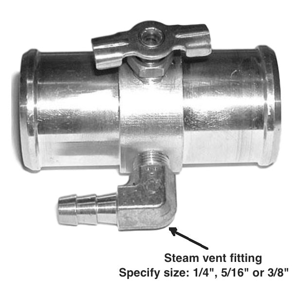
I'm thinking of going this route:
http://www.jagsthatrun.com/Pages/Par...g_LSI-tee.html
I'm thinking of going this route:
http://www.jagsthatrun.com/Pages/Par...g_LSI-tee.html

 04-27-2012, 09:43 PM
#144
I spent the afternoon buttoning under the hood. All lines are back on. The coil brackets and coils are back on and the right coil bracket has clearance to fit.
Tomorrow I will finally bolt up the exhaust for the last time.
The right coil bracket was touching the fire wall. I took the edge off with a cut off wheel and it fits nicely now.

Tomorrow I will finally bolt up the exhaust for the last time.
The right coil bracket was touching the fire wall. I took the edge off with a cut off wheel and it fits nicely now.
04-29-2012, 07:20 PM
#145
My intention was to bolt up the exhaust on Saturday but i got under the car and realized I needed to run the trans harness back before could bolt up the exhaust. As a result the Wiring harness is now in place.
It all lined up very well now I need to wire it up. One cool thing is the Camaro oil sensor and C5 oil temp sensor plugged right in to the C4 harness.
I needed to find a place for my IAT. I also needed to plug the hole in my SLP claw where the AIR is plumed on an LT1. I took a 5/16 drill bit and drilled a hole in a rubber plug the with a round file I worked it until it fit snug. Rubber will tear when you drill it. I also had to flip the MAF on its side it was rubbing the radiator hose.


With that out of the way I worked on my exhaust most of the day unfortunately I will need to take the drivers side cat out and have the cat moved forward a bit it rubs the floorboard.
Pass:

Drivers:

It all lined up very well now I need to wire it up. One cool thing is the Camaro oil sensor and C5 oil temp sensor plugged right in to the C4 harness.
I needed to find a place for my IAT. I also needed to plug the hole in my SLP claw where the AIR is plumed on an LT1. I took a 5/16 drill bit and drilled a hole in a rubber plug the with a round file I worked it until it fit snug. Rubber will tear when you drill it. I also had to flip the MAF on its side it was rubbing the radiator hose.
With that out of the way I worked on my exhaust most of the day unfortunately I will need to take the drivers side cat out and have the cat moved forward a bit it rubs the floorboard.
Pass:
Drivers:
05-01-2012, 08:43 AM
#146

I have yet another question for you. Since you used the corvette accessories. What did you do for wiring of the Alternator? Just run one wire? If not where did you hook up the 2 small wires from the weatherpak connector off the alt?
05-01-2012, 06:10 PM
#147
My 91 alternator is a 3 wire set up:
Red is hot 16ga to a fusible link
Brown is the light
pink/blk 12V exciter
The Corvette LS1 is:
S 16ga RED Battery Positive Voltage
F 18ga GRY Generator Field Duty Cycle Signal
L 18ga RED Generator Turn On Signal
Soooo..
Red 91 16ga wire to 16ga RED Battery Positive Voltage on LS1
Brown 91 wire to F 18ga GRY Generator Field Duty Cycle Signal
The pink/blk 91 wire is not used
The wire from the old Camaro plug goes to L 18ga RED Generator Turn On
This is what my research tells me. I have yet to try it and I have to caution you if you do this wrong you could burn up your alternator.
Last edited by LSCha0s; 05-09-2012 at 06:16 PM.
05-03-2012, 09:11 AM
#148
Ya I am just finishing my harness and fuse box and going to put the engine and tranny in here withing the next few days so I wanted to figure this out so I can wire it in LOL. It's all this little fun stuff of mixing and matching that makes it so fun hahaha.
05-09-2012, 08:52 PM
#149
I trimmed the 91 PCM tray and with the LS1 PCM mocked up I have almost an inch of clearance from the hood. With the inner fender off I put a one inch spark plug box on top for reference. I'm thinking of welding a couple of studs to the cover(it comes off and is metal) to secure it to the tray.


05-13-2012, 06:55 PM
#150
In this diagram you can see the brake switch wiring pink hot then feeds purple when the switch is closed its 12V when you step on the brake the switch opens. This will be hooked to Blue 33 for TCC lock up. When I took out the 700r4 wiring this was the only wire that I did not know what to do with I'm glad I saved it and made a note.

05-13-2012, 07:04 PM
#151
I will be hooking my Park Neutral Safety switch. The orange/black wire that originally went to the L98 PCM D11. It needs to be ground when in park and neutral. I have yet to verify this but I suspect it is if not I will use it to a relay.

 06-09-2012, 08:34 PM
#156
I spent most of the day doing the wiring. I wired the LS coils/Injectors to the original L98 INJ1 and INJ2 circuits.The wires from the old L98 harness to the LS PCM have been extended. Th grounds are hooked up and the 12V switched have been wired to a fuse block I screwed in under the drivers side hood latch frame rail. I figured its protected from something randomly dropped in the engine bay and the weather there.

06-10-2012, 11:03 AM
#158
That hole thing is temporary. I couldn't find something better locally. It was cheap and available and will allow me to trouble shoot if I have problems. I was just looking on the web for a better solution. I may just solder them all together with a fuselink once I know everything is working.
06-11-2012, 12:26 PM
#159
20ga wires --- http://www.mouser.com/ProductDetail/...inkVaLNA%3d%3d
18ga wires --- http://www.mouser.com/ProductDetail/...2f83wWTA%3d%3d[/QUOTE]
Good stuff. I did not know the ecm had both 18ga and 20ga running to it. If my eyes do not deceive me these are the pins to the ecm right? Why I need these? i spent most of my time yanking wires out...lol, except for adding a pin (used one of the wires I yanked out) for fan relay 1, and I may have to add another for the 4l80e. If I had not mentioned earlier...you are the man.