


wiring help

Thread Starter
On The Tree

Joined: Mar 2011
Posts: 153
Likes: 1
From: Granite City, IL
I'm working on my wiring harness for my 5.3 & trying to get everything together. I already removed most of the wires I don't need now I'm working on removing the pink wires from the C2 underhood connector because Im not using the original fuse box but I have ran into a small problem.
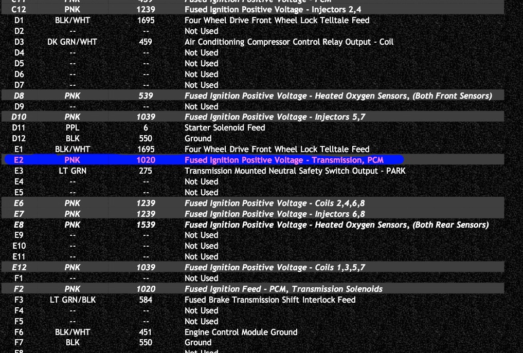
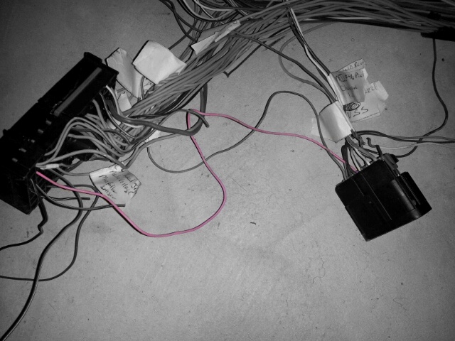
This pink wire in pin # E-2 needs to be cut from the connector.
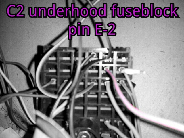
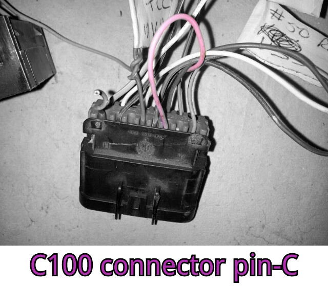
It is the Fused Ignition Positive Voltage - Transmission, PCM but instead of it leading to a pin on the PCM connector like I thought it was going to, it leads to Pin-C on the C100 connector & this connector is getting removed also.
I know this wire needs to go to the PCM & need to know which pin it connects to. Any help would be appreciated.
This pink wire in pin # E-2 needs to be cut from the connector.
It is the Fused Ignition Positive Voltage - Transmission, PCM but instead of it leading to a pin on the PCM connector like I thought it was going to, it leads to Pin-C on the C100 connector & this connector is getting removed also.
I know this wire needs to go to the PCM & need to know which pin it connects to. Any help would be appreciated.
Last edited by veltboy618; May 22, 2012 at 04:51 PM.

On The Tree
Joined: Nov 2010
Posts: 114
Likes: 0
From: Fairview , MO
you only need to worry about the C -100 pin C if you are using the underhood fuse box and since you are doing away with it all you need to make sure is that PCM Blue connector pin 75 and the transmission pin E are hot with key on and in crank. Hope this helps.
Thread Starter
On The Tree
Joined: Mar 2011
Posts: 153
Likes: 1
From: Granite City, IL
Ok I already had the pin #75 on the blue connector marked for switched 12v but I dont understand which wire you are talking about when you say transmission pin E. Could you explain a little more.
Thread Starter
On The Tree
Joined: Mar 2011
Posts: 153
Likes: 1
From: Granite City, IL
The pink wire I'm talking about & the wire going to the MAF will not be the same wire because this wire leaves the C100 connector pic C and goes to the C2 connector pin E2 (Pin C4 on the C2 connector is the one that leads to the MAF). From the E2 pin it goes through a fuse (when connected to the factory fuse block) then I suppose it comes back down through the C2 connector to another pin. Do anyone know which pin this could be? Maybe that will be the wire I need to have 12V with key on & in crank to control the transmission
Last edited by veltboy618; May 23, 2012 at 06:01 PM.
Joined: Sep 2004
Posts: 3,148
Likes: 12
From: Downers Grove, IL
Remove pin F2 from connector C2 and move it to pocket B9 on connector C2. B9 is fused by fuse #24 (ETC Fuse, not normally used).
Circuit 1020 follows a twisted kinda path.
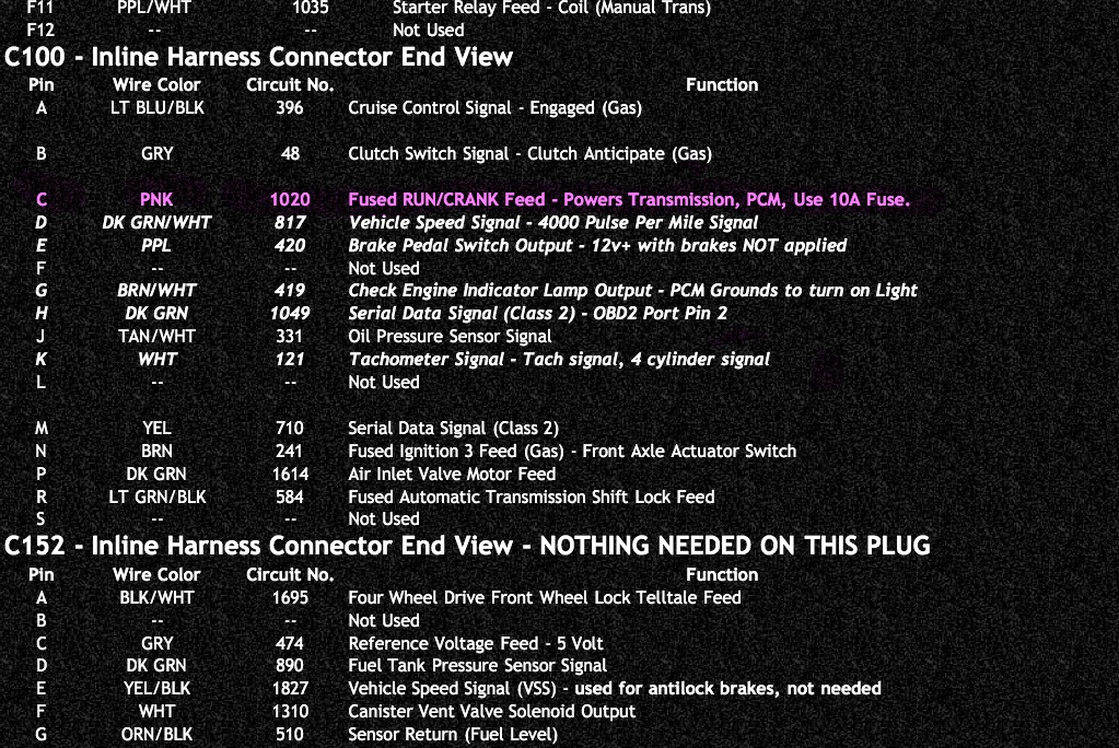
From PCM pin 75 blue it goes to pin F2 in C2, comes back out at pin E2 in C2, then to pin C in C100 finally to Pin D3 of C1 in the interior fuse block which is a 10 amp ignition fuse. you can eliminate the pink wire from C2 to C100 as long as you follow the first statement in this post.
Circuit 1020 follows a twisted kinda path.
From PCM pin 75 blue it goes to pin F2 in C2, comes back out at pin E2 in C2, then to pin C in C100 finally to Pin D3 of C1 in the interior fuse block which is a 10 amp ignition fuse. you can eliminate the pink wire from C2 to C100 as long as you follow the first statement in this post.
Trending Topics
Thread Starter
On The Tree
Joined: Mar 2011
Posts: 153
Likes: 1
From: Granite City, IL
Remove pin F2 from connector C2 and move it to pocket B9 on connector C2. B9 is fused by fuse #24 (ETC Fuse, not normally used).
Circuit 1020 follows a twisted kinda path.
From PCM pin 75 blue it goes to pin F2 in C2, comes back out at pin E2 in C2, then to pin C in C100 finally to Pin D3 of C1 in the interior fuse block which is a 10 amp ignition fuse. you can eliminate the pink wire from C2 to C100 as long as you follow the first statement in this post.
Last edited by veltboy618; May 24, 2012 at 11:18 PM.
LS1 Tech Stories
The Best V8 Stories One Small Block at Time

Topdon ONE vs. Artidiag 800 BT2: Which is the Diagnostic Tablet For You?
Pouria Savadkouei
Gas Monkey Built a 6-Wheel Ferrari Testarossa With a Corvette LT4 Engine
Verdad Gallardo
7 Most Reliable High-Performance Engines GM Has Ever Built
Verdad Gallardo
Amazing '71 Camaro Restomod Is Modern Muscle Car Under the Skin
Verdad Gallardo
6 Common C5 Corvette Failures and What's Involved In Repairing Them
Pouria Savadkouei
Retro Modern Bandit Pontiac Trans AM Comes With Burt Reynolds' Autograph
Verdad Gallardo
Top 10 Greatest Cadillac V Series Performance Models Ever, Ranked
Pouria Savadkouei
Top 10 Most Powerful Chevy Trucks Ever Made!

Hennessey's New Supercharged Silverado ZR2 Has 700 HP
Verdad Gallardo Thread Starter
On The Tree
Joined: Mar 2011
Posts: 153
Likes: 1
From: Granite City, IL
What is the correct way to wire in LS1 injector connectors to the truck harness...
I been searching and I'm getting 2 different answers.
this one says you have to do it a certain way
https://ls1tech.com/forums/fueling-i...k-harness.html
but this one says it doesnt matter which way the wire goes..
http://www.ls1truck.com/forums/elect...k-harness.html
I been searching and I'm getting 2 different answers.
this one says you have to do it a certain way
https://ls1tech.com/forums/fueling-i...k-harness.html
but this one says it doesnt matter which way the wire goes..
http://www.ls1truck.com/forums/elect...k-harness.html
Joined: Sep 2004
Posts: 3,148
Likes: 12
From: Downers Grove, IL
Pin F2 in C2 should get wired to a 10A fuse that is ignition hot, pin E2 can get eliminated since you are getting power elsewhere.
I`m not positive on the injectors, but I would make sure if the injector connector is marked or the connectors that you are putting on are marked. The injector itself is just a magnetic coil so it doesn`t care, but some MFG`s may put a diode on the coil to protect from feedback voltage as the magnetic field collapses when the injector is turned off.....which would make it polarity sensitive.
I`m not positive on the injectors, but I would make sure if the injector connector is marked or the connectors that you are putting on are marked. The injector itself is just a magnetic coil so it doesn`t care, but some MFG`s may put a diode on the coil to protect from feedback voltage as the magnetic field collapses when the injector is turned off.....which would make it polarity sensitive.
Thread Starter
On The Tree
Joined: Mar 2011
Posts: 153
Likes: 1
From: Granite City, IL
Thanks! I figured thats what you were talking about. Would you happen to have or know where can find a pin out sheet or site showing all of the locations of the pins on the 4L60E round connector. I have been searching & cant find one anywhere.

Thread Starter
On The Tree
Joined: Mar 2011
Posts: 153
Likes: 1
From: Granite City, IL
Thanks for all the help above guys. Im glad I have all of that stuff figured out. I just about got everything removed from all the connectors & labeled but now have a couple more questions.
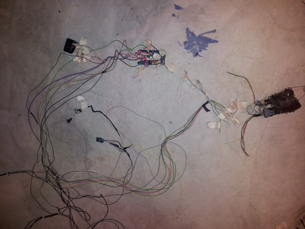
I am having a problem figuring out what I need to do with the wires coming from the C2 connector and leading to the neutral safety switch mounted on the side of the transmission.
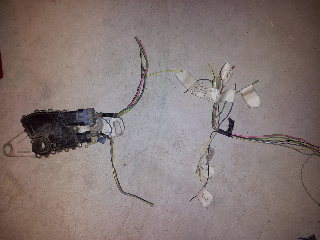
These 2 are pretty simple
A9-Green - back up lamps
F9-Pink - fused ignition positive voltage
I need help figuring out where these wires hook to
E3-Green wire - Park neutral safety switch output-park
F10-Purple wire - starter relay coil supply
F11-Yellow wire - Neutral Safety Switch Park/Neutral Signal (Automatic Transmission)
D11-Thick purple wire - Starter Solenoid Crank Voltage-12V+ During crank only
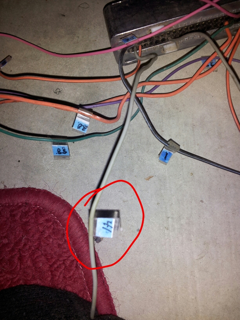
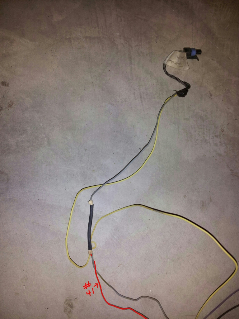
This gray wire is the last wire that I need to figure out. It leave the Blue PCM connector pin #41 and goes one of those junctions then up to the temperature switch. I need help finding out where the other gray wire leaving the junction goes. It doesn't have a connector on the end.
Any help would really be appreciated!!!
I am having a problem figuring out what I need to do with the wires coming from the C2 connector and leading to the neutral safety switch mounted on the side of the transmission.
These 2 are pretty simple
A9-Green - back up lamps
F9-Pink - fused ignition positive voltage
I need help figuring out where these wires hook to
E3-Green wire - Park neutral safety switch output-park
F10-Purple wire - starter relay coil supply
F11-Yellow wire - Neutral Safety Switch Park/Neutral Signal (Automatic Transmission)
D11-Thick purple wire - Starter Solenoid Crank Voltage-12V+ During crank only
This gray wire is the last wire that I need to figure out. It leave the Blue PCM connector pin #41 and goes one of those junctions then up to the temperature switch. I need help finding out where the other gray wire leaving the junction goes. It doesn't have a connector on the end.
Any help would really be appreciated!!!
Last edited by veltboy618; Jul 26, 2012 at 03:40 PM.
I found this on LT1SWAP.COM, not sure what year harness your using
If removing trans, pay attention to BLUE connector pin 41. Some harnesses are different based on type of o2 sensors you have. Some this pin goes to trans only, some harnesses, there is a splice, and this pin goes to coolant temp sensor AND transmission. Simply cut the wire to the trans AT THE splice if this is the case
http://www.lt1swap.com/99-02_vortec_pcm.htm


Registered User
Joined: Oct 2014
Posts: 1
Likes: 0
was curious if you ever got your neutral safety switch and trans wiring figured out, in same boat now trying to research and see what i can find instead of just starting a new thread and asking same questions over and over, thanks