
LQ4/T56 into 2001 BMW 540i
 03-30-2013, 11:25 PM
#181

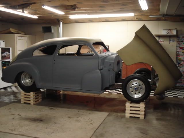
Measuring driveline angles will be crappy, because the nose of the car only is on jackstands. The car is too low when it sits normally, the engine hoist legs hit the lower control arms when plopping the engine in. May just have to take the angle of the car and then subtract it from my measurements.

 03-31-2013, 07:43 PM
#186
http://www.chevelles.com/forums/showthread.php?t=271703
depending on your wheels, or what your comfort level is. A lot of people do 12x12 but that's too small more me. I need my tires on a larger surface.
depending on your wheels, or what your comfort level is. A lot of people do 12x12 but that's too small more me. I need my tires on a larger surface.
04-01-2013, 07:06 AM
#187

It was my own dumbass fault, as I built the mount before I mounted the alternator, without thinking about the alternator clearance. It�s all fixed up now. If you mount all your front accessories ahead of time you should have no problems.
04-02-2013, 08:41 AM
#188
Chipping away at the little things...
Alternator mounted up, new eyelet crimped to batt (+) wire, hooked up to alternator
My fiancee helped me bleed the clutch using my Tick Speedbleeder (great product, I can't even imagine doing it from under the car). I've never driven a 4th Gen F-Body before, but the clutch feels like what I would expect in one. At this point the pedals are completely wrapped up and done...it felt nice to sit and make vroom vroom noises while playing with the gas and clutch.
I also finally found the cranked 12V+ wire, so I will hook that up to the starter this evening, put some oil in it, and possibly bump the starter just to see if anything blows up (plugs are not in yet, coils aren't hooked up, and injectors aren't wired, so no harm).
04-10-2013, 09:52 AM
#189
Well, may have hit a snag. I wrapped up the power steering system last night and filled it with fluid. No leaks are apparent, but then again I won’t know for sure until the motor runs and the system hits full pressure. The low pressure side turned out great, and I was able to reuse the stock power steering cooler on the evaporator bracket. I removed the evaporator itself since I’m not running AC.
I used Russell PowerFlex Power Steering Hose 632610, -6AN size on the high pressure side, which is fine.

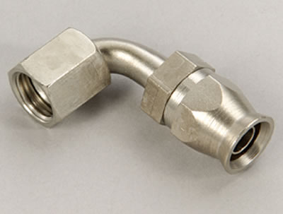
My banjo fitting on the box is fine and so is the o-ring to –6AN fitting on the LS pump. However, I did use regular Summit-brand hose ends on the high pressure line. From what I’m reading they’re not suitable for power steering use. Is this correct? Here’s what I used:

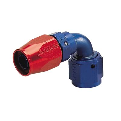
If those are wrong, I’m off to buy more hose ends…luckily all I need is a 90 and a straight hose end. Maybe the local speed shop has a few in stock. I assume this is what I need.

This evening I’m hoping to have the heater lines all done. Corvette radiator gets here tomorrow, I’ll mount that up along with the dual fans I pulled off a Monte Carlo in a yard.
Also arriving tomorrow is the Corvette FPR/Filter, silicone intake elbow to the TB, and some replacement sway bar end links. Stock ones were shot and causing some clunks over bumps.
I used Russell PowerFlex Power Steering Hose 632610, -6AN size on the high pressure side, which is fine.
My banjo fitting on the box is fine and so is the o-ring to –6AN fitting on the LS pump. However, I did use regular Summit-brand hose ends on the high pressure line. From what I’m reading they’re not suitable for power steering use. Is this correct? Here’s what I used:
If those are wrong, I’m off to buy more hose ends…luckily all I need is a 90 and a straight hose end. Maybe the local speed shop has a few in stock. I assume this is what I need.
This evening I’m hoping to have the heater lines all done. Corvette radiator gets here tomorrow, I’ll mount that up along with the dual fans I pulled off a Monte Carlo in a yard.
Also arriving tomorrow is the Corvette FPR/Filter, silicone intake elbow to the TB, and some replacement sway bar end links. Stock ones were shot and causing some clunks over bumps.
04-17-2013, 07:08 AM
#190
let's talk cooling systems...
i have mine mostly done, just need to clarify a few details since my setup seems to be slightly different than the others i've researched.
I have the following set up for the radiator supply and return, and heater supply and return to the valve/heater core.
I haven't yet plumbed the vent lines. Is my theory correct?

I'm using a VW sphere style overflow bottle.

Since there is no provision for a rad cap on the C5 Corvette radiator, this will have to be the fill point for the sytem. Steam vents are blocked off in the rear (just like factory setup) and fronts are tied together into a common line, which will be connected as shown.
The water pump I bought on LS1Tech has a brass barb fitting tapped into the body of the pump...should I block this off or include it in the steam vent line?
The top (smaller) line on the VW bottle should go as shown in my diagram, but i'm not sure where the lower line goes. I'm assuming to either that it ties into one of the heaters hoses or the lower rad hose, to be able to fill the system. Is there any need for an additional, unpressurized overflow bottle?
Where does the other vent line on the C5 rad go?
Any input/changes I should make? Hoping to wrap up cooling system tomorrow.
i have mine mostly done, just need to clarify a few details since my setup seems to be slightly different than the others i've researched.
I have the following set up for the radiator supply and return, and heater supply and return to the valve/heater core.
I haven't yet plumbed the vent lines. Is my theory correct?
I'm using a VW sphere style overflow bottle.
Since there is no provision for a rad cap on the C5 Corvette radiator, this will have to be the fill point for the sytem. Steam vents are blocked off in the rear (just like factory setup) and fronts are tied together into a common line, which will be connected as shown.
The water pump I bought on LS1Tech has a brass barb fitting tapped into the body of the pump...should I block this off or include it in the steam vent line?
The top (smaller) line on the VW bottle should go as shown in my diagram, but i'm not sure where the lower line goes. I'm assuming to either that it ties into one of the heaters hoses or the lower rad hose, to be able to fill the system. Is there any need for an additional, unpressurized overflow bottle?
Where does the other vent line on the C5 rad go?
Any input/changes I should make? Hoping to wrap up cooling system tomorrow.
04-17-2013, 09:18 AM
#192
Teching In
Join Date: Dec 2012
Posts: 42
Likes: 0
Received 0 Likes
on
0 Posts

Or you can delete the T in your steam line section and then the extra fitting on the radiator will go to the lower fitting on the sphere. Also make sure the volume of the sphere is approx the same as the volume of the tank GM used in the donor vehicle and that the ratio of the fill line to total volume is approx the same. The sphere has to absorb the change in volume of the entire cooling loop as the liquid expands and contracts. If the sphere was sized for a small economy vehicle with a 4 banger then it will be too small for the V8.
04-19-2013, 08:55 PM
#193
I will have to do some investigation on this.
I am planning on basically running the BMW rad. and coolant bottle with the rest of the LS1 system.
I know I will need an adaptor for the hoses' size difference and a steam porthttp://www.jagsthatrun.com/Cooling-S...rts_Order.html
I am planning on basically running the BMW rad. and coolant bottle with the rest of the LS1 system.
I know I will need an adaptor for the hoses' size difference and a steam porthttp://www.jagsthatrun.com/Cooling-S...rts_Order.html
04-19-2013, 09:09 PM
#194
Rao helped me out over on Bimmerforums.
http://forums.bimmerforums.com/forum...8#post26269218
http://forums.bimmerforums.com/forum...7#post26270017
http://forums.bimmerforums.com/forum...2#post26270082
http://forums.bimmerforums.com/forum...8#post26269218
http://forums.bimmerforums.com/forum...7#post26270017
http://forums.bimmerforums.com/forum...2#post26270082


 04-19-2013, 11:31 PM
#196
Rao helped me out over on Bimmerforums.
http://forums.bimmerforums.com/forum...8#post26269218
http://forums.bimmerforums.com/forum...7#post26270017
http://forums.bimmerforums.com/forum...2#post26270082
http://forums.bimmerforums.com/forum...8#post26269218
http://forums.bimmerforums.com/forum...7#post26270017
http://forums.bimmerforums.com/forum...2#post26270082
04-21-2013, 09:11 PM
#197
getting closer. I took a week off from work to make progress on the car and blow off some steam overall.
Corvette FPR and filter installed
Cooling system done. No leaks, but it'll really be put to the test once we I fire it up. Here is the final routing I went with.

I also replaced the front sway bar end links as they had been clunking since I bought the car.
Received the last reducing coupler I needed for the intake, so that's all set. I'll be using a section of 3" SS exhaust pipe I have laying around to extend the filter as close as I can to the factory cold air intake ducting in the bumper/fender. Probably going to paint it wrinkle black.
The biggest task of the week was working on wiring. I had to add a few pins/wires to the BMW cluster to be able to accept analog GM tach and coolant temp signals, since the cluster originally got those signals from the DME (now gone) in CAN-BUS. The pins are unlike any other small cluster pins I have seen, but a trip to the yard found me a fistful of these crown shaped connectors out of a white E36. Oddly enough, all the other BMWs there had the common L-shaped pin, both older and newer. I must have spent 2 hours looking for them, but finally got them. I also need a BMW coolant sensor pigtail, but I couldn't find one of those at the yard either, unfortunately.
I went through the GM harness again and removed a handful of circuits I missed the first time around. It's unbelievable how many useless wires and connectors are included in every harness, but I suppose it's easier/cheaper to build them that way as an OEM rather than customizing each harness to each vehicle. Even after thinning it out, the whole mess was still just a huge ball of wires, so there was no chance of laying it on the motor in a clean manner. I spent a day or two on the living room floor disassembling the harness wire by wire, labeling, and separating all the wires. It still needs a bit of cleanup, but it's 90% there. Now it's just a matter of sitting the fuse panel and PCM connectors in their places in the engine bay, and routing/shortening the wires exactly as I like. Time consuming, but much neater and more efficient than trying to untangle on the spot.
Once the GM harness is in and hooked up to all the usual crap, I can make the BMW/GM connections, and once the PCM comes in, I can hopefully fire it up for the first time.
Still need to finish the rear diff and have a driveshaft made before it's driveable.

Corvette FPR and filter installed
Cooling system done. No leaks, but it'll really be put to the test once we I fire it up. Here is the final routing I went with.
I also replaced the front sway bar end links as they had been clunking since I bought the car.
Received the last reducing coupler I needed for the intake, so that's all set. I'll be using a section of 3" SS exhaust pipe I have laying around to extend the filter as close as I can to the factory cold air intake ducting in the bumper/fender. Probably going to paint it wrinkle black.
The biggest task of the week was working on wiring. I had to add a few pins/wires to the BMW cluster to be able to accept analog GM tach and coolant temp signals, since the cluster originally got those signals from the DME (now gone) in CAN-BUS. The pins are unlike any other small cluster pins I have seen, but a trip to the yard found me a fistful of these crown shaped connectors out of a white E36. Oddly enough, all the other BMWs there had the common L-shaped pin, both older and newer. I must have spent 2 hours looking for them, but finally got them. I also need a BMW coolant sensor pigtail, but I couldn't find one of those at the yard either, unfortunately.
I went through the GM harness again and removed a handful of circuits I missed the first time around. It's unbelievable how many useless wires and connectors are included in every harness, but I suppose it's easier/cheaper to build them that way as an OEM rather than customizing each harness to each vehicle. Even after thinning it out, the whole mess was still just a huge ball of wires, so there was no chance of laying it on the motor in a clean manner. I spent a day or two on the living room floor disassembling the harness wire by wire, labeling, and separating all the wires. It still needs a bit of cleanup, but it's 90% there. Now it's just a matter of sitting the fuse panel and PCM connectors in their places in the engine bay, and routing/shortening the wires exactly as I like. Time consuming, but much neater and more efficient than trying to untangle on the spot.
Once the GM harness is in and hooked up to all the usual crap, I can make the BMW/GM connections, and once the PCM comes in, I can hopefully fire it up for the first time.
Still need to finish the rear diff and have a driveshaft made before it's driveable.

 04-27-2013, 03:35 PM
#200
I'm in the middle of wiring right now...can anyone point me in the right direction here?
I've been following this site for all my info:
http://www.lt1swap.com/underhoodfuseblock.htm
According to him you need to use the following fuse block:
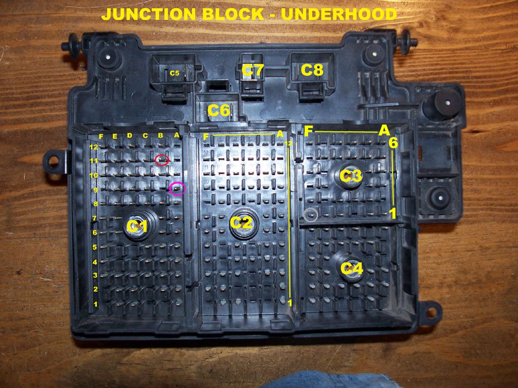
I have that same fuse block that came with the drivetrain from the van (on the left below), but also have another fuse panel (on the right).

This white plastic case holds all the power wire pins that go from the fuse panel to the sensors, PCM, etc.

and it fits ONLY into this port on the fuse panel.

Problem is, the white plastic case that holds all the pink power wires that go to all the sensors/PCM/etc doesn't physically fit into the correct fuse block as required by that site. What am I missing? You would think that the case that powers all the sensors would fit into C2 on that fuse block. Everything is the same way as it was removed from the Express Van, so it doesn't make sense to me.
I've been following this site for all my info:
http://www.lt1swap.com/underhoodfuseblock.htm
According to him you need to use the following fuse block:
I have that same fuse block that came with the drivetrain from the van (on the left below), but also have another fuse panel (on the right).
This white plastic case holds all the power wire pins that go from the fuse panel to the sensors, PCM, etc.
and it fits ONLY into this port on the fuse panel.
Problem is, the white plastic case that holds all the pink power wires that go to all the sensors/PCM/etc doesn't physically fit into the correct fuse block as required by that site. What am I missing? You would think that the case that powers all the sensors would fit into C2 on that fuse block. Everything is the same way as it was removed from the Express Van, so it doesn't make sense to me.
Last edited by LQ4-E39; 04-28-2013 at 12:18 PM.