

LM7 into a 66 Buick LeSabre Hard Top
 03-30-2013, 04:29 PM
#1
Staging Lane
Thread Starter
iTrader: (4)
Join Date: Jul 2009
Location: Killeen, Texas
Posts: 99
Likes: 0
Received 0 Likes
on
0 Posts
Whats up LS1 Tech, just thought I would post my build for those that are interested. My build started last Nov 12. Things were moving slow becuase my lack of time. After struggling for a while trying to install my 5.3 in to my engine bay, I decided to let the professionals do it. The Car Shop installed my engine and set the correct degree angle for the drive shaft and transmission. They fabricated a crossmember for my 4l60E tranny. I got my motormounts from Dirty Dingo (sliders), my accessories from Alper Motor sports, and my harness From BP automotive. Pics coming soon.
Right now I'm working on radiator fans, fuel pump, and installing the harness.
Right now I'm working on radiator fans, fuel pump, and installing the harness.

 03-30-2013, 06:11 PM
#3
Staging Lane
Thread Starter
iTrader: (4)
Join Date: Jul 2009
Location: Killeen, Texas
Posts: 99
Likes: 0
Received 0 Likes
on
0 Posts
whats up ls1 tech, just thought i would post my build for those that are interested. My build started last nov 12. Things were moving slow becuase my lack of time. After struggling for a while trying to install my 5.3 in to my engine bay, i decided to let the professionals do it. The car shop installed my engine and set the correct degree angle for the drive shaft and transmission. They fabricated a crossmember for my 4l60e tranny. I got my motormounts from dirty dingo (sliders), my accessories from alper motor sports, and my harness from bp automotive. Pics coming soon.
Right now i'm working on radiator fans, fuel pump, and installing the harness.
Right now i'm working on radiator fans, fuel pump, and installing the harness.
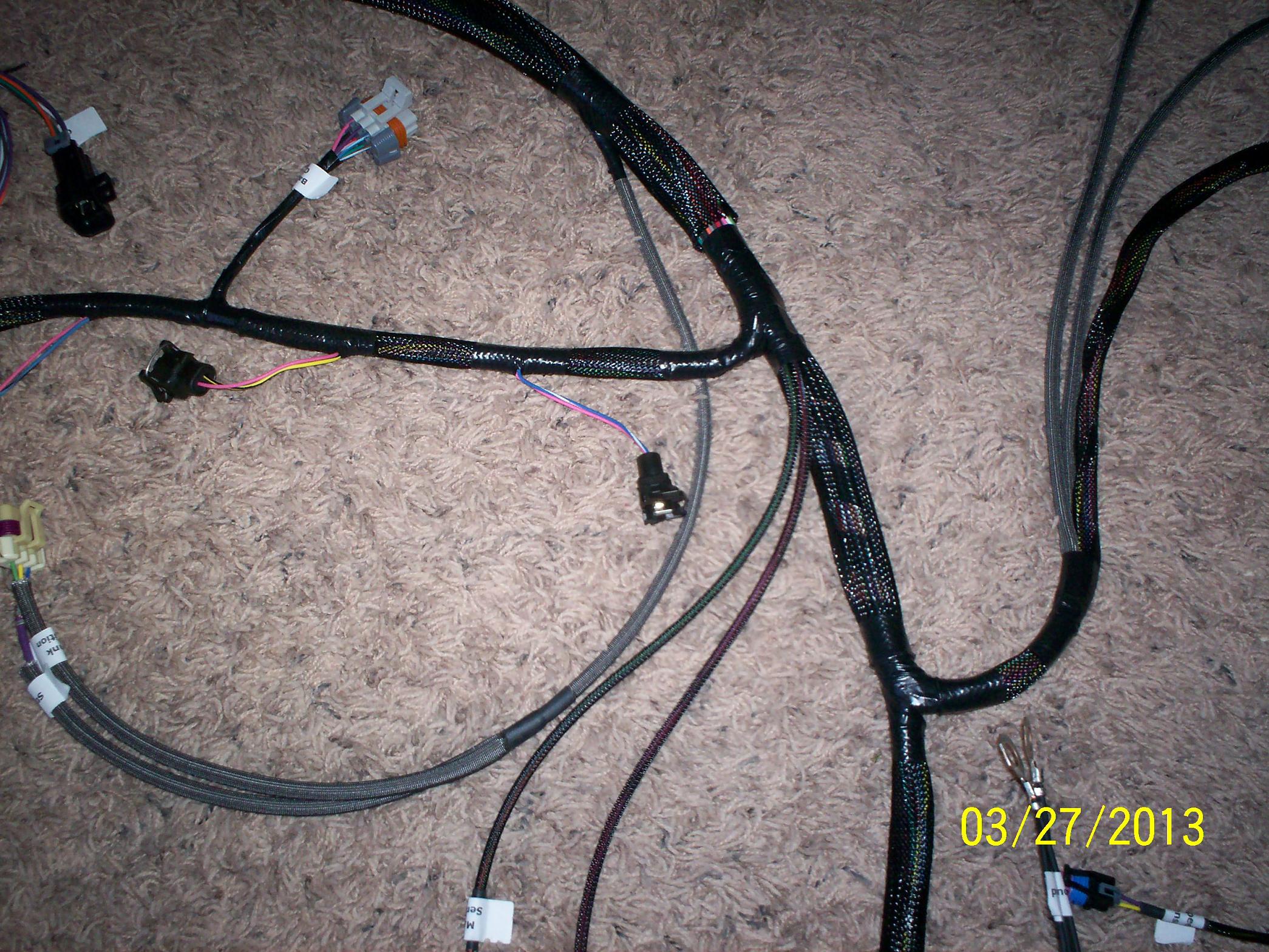
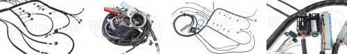
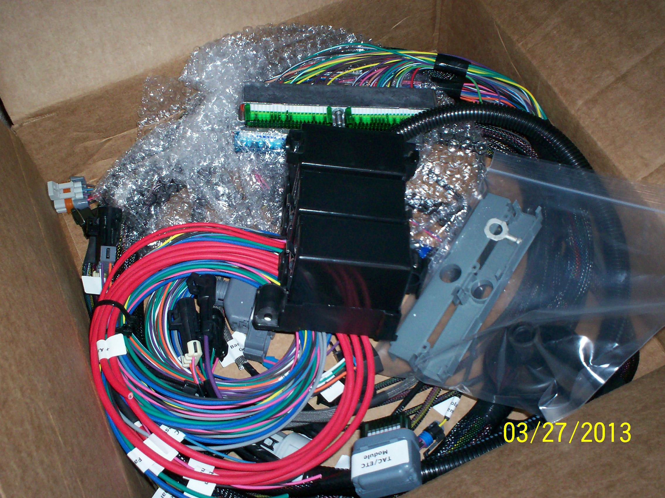 As you can see this is my harness BP automotive used quality parts for this build.

more to come
Last edited by Killer66; 03-30-2013 at 06:13 PM. Reason: update with photos
03-31-2013, 09:46 PM
#4
Staging Lane
Thread Starter
iTrader: (4)
Join Date: Jul 2009
Location: Killeen, Texas
Posts: 99
Likes: 0
Received 0 Likes
on
0 Posts
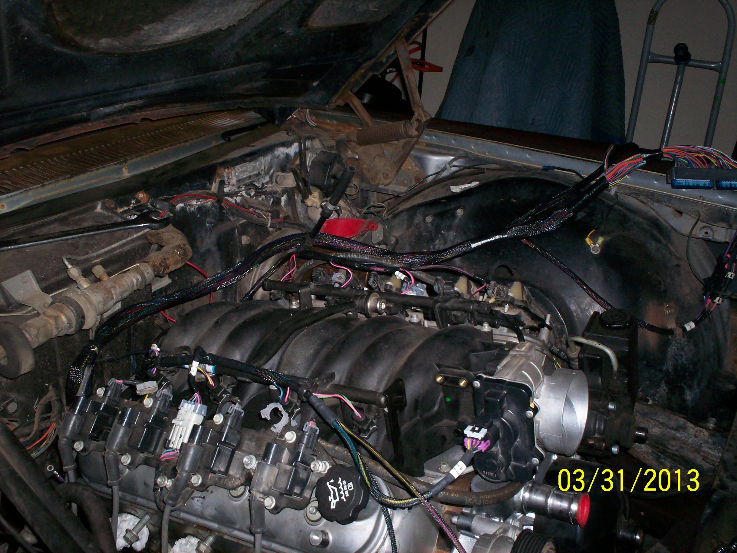
Installed my harness today. Well mostly, it's not complete yet. I still have to connect the transmission and some other wires underneath. Here are some pics.
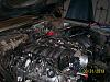 Harness installed
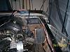 Location of fuse block and computer
 What is this part called?
 Harness installed
 Location of fuse block and computer
 What is this part called?
 Last edited by Killer66; 03-31-2013 at 09:49 PM. Reason: update pics
04-01-2013, 10:51 PM
#6
Staging Lane
Thread Starter
iTrader: (4)
Join Date: Jul 2009
Location: Killeen, Texas
Posts: 99
Likes: 0
Received 0 Likes
on
0 Posts
Yes it is... I was wondering what the difference is from that and the one I put on the side of my oil pan. Thanks for your response.
04-01-2013, 11:09 PM
#7
Staging Lane
Thread Starter
iTrader: (4)
Join Date: Jul 2009
Location: Killeen, Texas
Posts: 99
Likes: 0
Received 0 Likes
on
0 Posts
I located some old pics of my block and found out how the steamtubes were routed and moded I used some plastic tubing that came from my 5.3. Used it for routing the PCV lines.
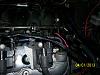
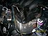 This photo is from the crankcase to the throttle body
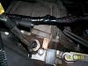
 This is the other side, the hose fit over the quick disconnect fitting, I hope it holds.
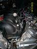
 This shot is the 90* rubber hose that I had laying around.
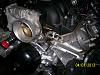 This shot is the routing of the steam vent if you are using the 5.3 throttle. This is how it is routed on original intake manifold. The passenger side will go to a vent in the radiator hose or water pump.
 This photo is from the crankcase to the throttle body
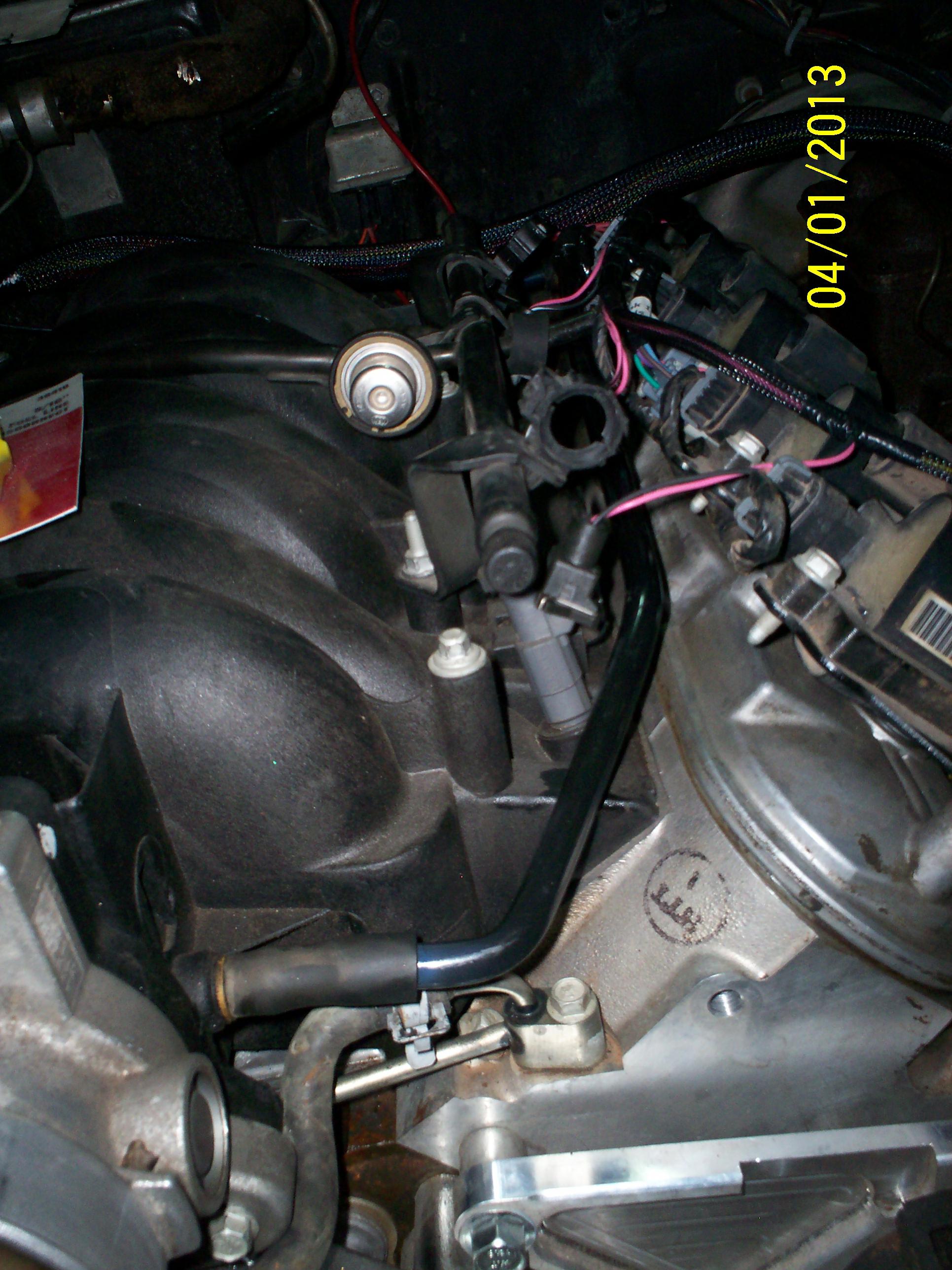 This is the other side, the hose fit over the quick disconnect fitting, I hope it holds.
 This shot is the 90* rubber hose that I had laying around.
  This shot is the routing of the steam vent if you are using the 5.3 throttle. This is how it is routed on original intake manifold. The passenger side will go to a vent in the radiator hose or water pump.
 Trending Topics
04-02-2013, 08:50 AM
#8
TECH Apprentice
I don't think it would make any difference were you pick up the oil pressure at, wherever it is easier. I drilled the cover on the pan to add an old school gauge and left the factory one hooked to the pcm. I have not ran the engine yet.
As for the pvc I don�t have it routed yet, yours looks very clean, was that the way it was routed? What about a PVC valve? I was under the impression that one side was filtered air and one side was intake vacuum.
As for the pvc I don�t have it routed yet, yours looks very clean, was that the way it was routed? What about a PVC valve? I was under the impression that one side was filtered air and one side was intake vacuum.
04-02-2013, 10:48 AM
#9
Bill
__________________
Standalone LS Swap Harnesses IN STOCK!
LSX, LTX Stand alone swap harnesses. S10 LSX conversion PLUG AND PLAY harnesses, 24x conversion PLUG AND PLAY harnesses. LT1 to LSX PLUG AND PLAY Harnesses.
sales@bp-automotive.com
www.bp-automotive.com
1-888-467-4491
Standalone LS Swap Harnesses IN STOCK!
LSX, LTX Stand alone swap harnesses. S10 LSX conversion PLUG AND PLAY harnesses, 24x conversion PLUG AND PLAY harnesses. LT1 to LSX PLUG AND PLAY Harnesses.
sales@bp-automotive.com
www.bp-automotive.com
1-888-467-4491
04-02-2013, 04:42 PM
#10
Staging Lane
Thread Starter
iTrader: (4)
Join Date: Jul 2009
Location: Killeen, Texas
Posts: 99
Likes: 0
Received 0 Likes
on
0 Posts
I don't think it would make any difference were you pick up the oil pressure at, wherever it is easier. I drilled the cover on the pan to add an old school gauge and left the factory one hooked to the pcm. I have not ran the engine yet.
As for the pvc I don’t have it routed yet, yours looks very clean, was that the way it was routed? What about a PVC valve? I was under the impression that one side was filtered air and one side was intake vacuum.
As for the pvc I don’t have it routed yet, yours looks very clean, was that the way it was routed? What about a PVC valve? I was under the impression that one side was filtered air and one side was intake vacuum.
Last edited by Killer66; 04-02-2013 at 04:43 PM. Reason: spelling
04-02-2013, 09:44 PM
#11
Staging Lane
Thread Starter
iTrader: (4)
Join Date: Jul 2009
Location: Killeen, Texas
Posts: 99
Likes: 0
Received 0 Likes
on
0 Posts
I don't think it would make any difference were you pick up the oil pressure at, wherever it is easier. I drilled the cover on the pan to add an old school gauge and left the factory one hooked to the pcm. I have not ran the engine yet.
As for the pvc I don�t have it routed yet, yours looks very clean, was that the way it was routed? What about a PVC valve? I was under the impression that one side was filtered air and one side was intake vacuum.
As for the pvc I don�t have it routed yet, yours looks very clean, was that the way it was routed? What about a PVC valve? I was under the impression that one side was filtered air and one side was intake vacuum.
04-02-2013, 09:50 PM
#12
Staging Lane
Thread Starter
iTrader: (4)
Join Date: Jul 2009
Location: Killeen, Texas
Posts: 99
Likes: 0
Received 0 Likes
on
0 Posts
Here are the pics of the 5.3 intake and crankcase routing. Can't upload the other pics will load later.
Attachment 397537
Attachment 397538
Attachment 397539
Attachment 397537
Attachment 397538
Attachment 397539
04-03-2013, 08:40 AM
#13
TECH Apprentice
Here are the pics of the 5.3 intake and crankcase routing. Can't upload the other pics will load later.
Attachment 397537
Attachment 397538
Attachment 397539
Attachment 397537
Attachment 397538
Attachment 397539
04-13-2013, 12:01 PM
#15
Staging Lane
Thread Starter
iTrader: (4)
Join Date: Jul 2009
Location: Killeen, Texas
Posts: 99
Likes: 0
Received 0 Likes
on
0 Posts
Does anyone know how to install a check engine light on your conversion?
Or, what type of lights to use e.g. led or condescent type?
Thanks in advance.
Or, what type of lights to use e.g. led or condescent type?
Thanks in advance.
04-14-2013, 12:42 PM
#16
TECH Apprentice
I used a PSI Harness so no help on light problem, Sorry
As for the PVC
I think you will need to reroute the PVC, not sure if you need a PVC valve for the line runnung from your aft left valve cover, but for sure the one form the right fwd cover should no be run to intake vacum.
GM E-Rod instruction
"How to set up your PVC system:
There are three ports on the engine that make up the PCV system. There are two possible foul side ports. One or both of these ports should be connected to the intake manifold and be exposed to vacuum at idle. If you choose to use only one of these ports, and the other one is part of your
engine, make sure it is capped off. The ports on the engine are 1) Front port on the valley cover(LS3 only). 2) Left rear (driver side) valve cover. 3) Top center of the inlet manifold (LC9 only). The ports with silver tubes may look simple but, they should not be modified. The tubes have a small orifice within them that is used in place of a PCV valve of earlier designs.
There is one fresh air port which is on the front of the right (passenger side) valve cover. Again this is a silver tube that faces forward on the valve cover. This port should be connected to filtered clean air. This connection must be within the engines air cleaner system and must be between the MAF (Mass Air Flow Sensor) and engine�s throttle body. The engine burns the air that
enters the PCV system so, if the fresh air port is prior to the MAF then, this air will enter the engine without being measured by the MAF and adverse engine operation may occur."
04-14-2013, 05:18 PM
#17
Staging Lane
Thread Starter
iTrader: (4)
Join Date: Jul 2009
Location: Killeen, Texas
Posts: 99
Likes: 0
Received 0 Likes
on
0 Posts
I used a PSI Harness so no help on light problem, Sorry
As for the PVC
I think you will need to reroute the PVC, not sure if you need a PVC valve for the line runnung from your aft left valve cover, but for sure the one form the right fwd cover should no be run to intake vacum.
GM E-Rod instruction
"How to set up your PVC system:
There are three ports on the engine that make up the PCV system. There are two possible foul side ports. One or both of these ports should be connected to the intake manifold and be exposed to vacuum at idle. If you choose to use only one of these ports, and the other one is part of your
engine, make sure it is capped off. The ports on the engine are 1) Front port on the valley cover(LS3 only). 2) Left rear (driver side) valve cover. 3) Top center of the inlet manifold (LC9 only). The ports with silver tubes may look simple but, they should not be modified. The tubes have a small orifice within them that is used in place of a PCV valve of earlier designs.
There is one fresh air port which is on the front of the right (passenger side) valve cover. Again this is a silver tube that faces forward on the valve cover. This port should be connected to filtered clean air. This connection must be within the engines air cleaner system and must be between the MAF (Mass Air Flow Sensor) and engine�s throttle body. The engine burns the air that
enters the PCV system so, if the fresh air port is prior to the MAF then, this air will enter the engine without being measured by the MAF and adverse engine operation may occur."
As for the PVC
I think you will need to reroute the PVC, not sure if you need a PVC valve for the line runnung from your aft left valve cover, but for sure the one form the right fwd cover should no be run to intake vacum.
GM E-Rod instruction
"How to set up your PVC system:
There are three ports on the engine that make up the PCV system. There are two possible foul side ports. One or both of these ports should be connected to the intake manifold and be exposed to vacuum at idle. If you choose to use only one of these ports, and the other one is part of your
engine, make sure it is capped off. The ports on the engine are 1) Front port on the valley cover(LS3 only). 2) Left rear (driver side) valve cover. 3) Top center of the inlet manifold (LC9 only). The ports with silver tubes may look simple but, they should not be modified. The tubes have a small orifice within them that is used in place of a PCV valve of earlier designs.
There is one fresh air port which is on the front of the right (passenger side) valve cover. Again this is a silver tube that faces forward on the valve cover. This port should be connected to filtered clean air. This connection must be within the engines air cleaner system and must be between the MAF (Mass Air Flow Sensor) and engine�s throttle body. The engine burns the air that
enters the PCV system so, if the fresh air port is prior to the MAF then, this air will enter the engine without being measured by the MAF and adverse engine operation may occur."
