

LS Swap- Sanden & Denso AC Relocation Brackets...
 05-15-2013 | 01:11 PM
#1
Thread Starter
Staging Lane
Joined: Jan 2013
Posts: 55
Likes: 1
Why are so many people so fond of the Sanden and not the Denso? Literally every post I read is how the Sanden compressor is the only way to go, but no one tells why. I already own the Denso (came with the engine swap from salvage yard). Hell, these Denso compressors are what GM put in Tahoes for many years, so I just can't understand why no one is making a Denso ac relocation bracket but they do for Sanden.

The following users liked this post:
Warloch (08-25-2021)
 05-15-2013 | 02:00 PM
#3

I think the reason the Sanden brackets are popular has more to do with what has been used historically in aftermarket AC systems. They are readily available with standard o-ring fittings and no need for adapter blocks.
Last edited by -TheBandit-; 05-15-2013 at 05:33 PM.

 05-15-2013 | 11:45 PM
#6
That's not true. Many Denso compressors are fixed displacement, for example all the ones used on the truck applications (Denso 10S17 and 10S20) like this one that I'm using in the stock location:
I think the reason the Sanden brackets are popular has more to do with what has been used historically in aftermarket AC systems. They are readily available with standard o-ring fittings and no need for adapter blocks.
I think the reason the Sanden brackets are popular has more to do with what has been used historically in aftermarket AC systems. They are readily available with standard o-ring fittings and no need for adapter blocks.
05-16-2013 | 09:47 AM
#7
The largest Sanden is the SD7H15 which is a 7 piston compressor with a displacement of 154.7cc/rev
The Denso 10S17 is a 10 piston compressor with a displacement of 188.0cc/rev
I don't know the exact pulley dimensions of either, but the Denso pulley is smaller which indicates in driven faster. Based on this, the Denso will provide a higher refrigeration capacity unless there is a significant difference in efficiency.
Trending Topics
05-16-2013 | 09:55 AM
#8

It is possible to have too big of a compressor. In A/C systems its usually better to have too small of a compressor versus too big of one. Too much displacement will raise operating pressures which isn't always a good thing.
05-18-2013 | 12:19 AM
#10

 05-18-2013 | 12:57 PM
#12
Hmm, good idea. When I started I didn't have an angle grinder so just high mounted the compressor, but seeing yours makes me think I should pick up a stock truck compressor and give cutting the mount a shot.
05-20-2013 | 12:27 PM
#13
I did a pretty ugly job on mine, but it fits now. Here are some quotes from my build thread:
New plan.


This is a Denso 10S17 compressor which is what originally would have come on this engine. I did some trimming on the OEM compressor bracket which came with my engine in order to graft it around the Doug's adapter and Energy Suspension mount. The compressor is in the OEM position and would run off a rear dedicated belt. The back of the compressor is very close to the motor mount. Frame trimming will be... interesting as will bolt access, but I think I can make it work (heard that before?). Stay tuned.
This is a Denso 10S17 compressor which is what originally would have come on this engine. I did some trimming on the OEM compressor bracket which came with my engine in order to graft it around the Doug's adapter and Energy Suspension mount. The compressor is in the OEM position and would run off a rear dedicated belt. The back of the compressor is very close to the motor mount. Frame trimming will be... interesting as will bolt access, but I think I can make it work (heard that before?). Stay tuned.
The back of the 10S17 compressor is about 1" in front of the frame stand using the Doug's adapters at 1/2" setback. If you look at the frame stand, the top forward bolt would interfere with the compressor, so I will need to trim back the frame stand as well as the subframe. For this I think I will drill a new hole in the original stand somewhere between the current two, then use it as the new forward mounting hole.
The bottom of the 10S17 compressor housing at the lower mounting bosses is actually in almost exactly the same place as the Sanden TRSA12 compressor I was attempting to use before, however I now have the option of cutting the rear lower mounting boss off, which would gain clearance for the lower control arm perch in the subframe. This likely will be needed considering how far back this compressor sits. The result is 3-point mounting instead of 4 for the compressor, but I think this will be okay.
Port location on the 10S17 isn't as good as the TRSA12 compressor. The ports are still at 45 degrees, but they are much lower on the compressor and further out. They will sit just barely to the inside of where the upper control arm cross shaft will be. The discharge port is the worst since it's lowest and furthest out on the compressor. To handle this, I plan to use Docs Blocks PN AA2210 which routes tubing tightly against teh compressor at 90 degrees so it runs forward toward the front of the compressor.
Depending on how much room I have with the UCA cross shaft, I may have the option on the suction port to go straight out from the compressor, but if that doesn't work I can use a similar fitting to the one above (AA2209) to route that tube forward also.
Things will be very tight, especially for getting the compressor in and out. I may have to remove the upper control arm when installing it. Also because of the proximity of the motor mount, frame, and compressor bracket, I will need to have the bracket (but not the compressor) installed when I drop in the engine because there will be no room for a wrench at the lower rearmost bolt once installed.
The nice thing about all this is that even though it will be PITA to R&R, it's not something I'll be doing often and for the price of my time and frustration, I will have a cleaner engine bay and some stories to tell about all the combos I tried.
Also a few other notes on the TRSA12 compressor I was going to use before:
I have since looked at the TRSA12 and found that I could use a neutral position, mount upside-down adapter like the Autokraft (or Ak copies I made) with the OEM TRSA12 bracket trimmed appropriately. With the AK mounts I believe it could work with appropriate frame notching. Both the TRSA12 and the 10S17 tensioner mounts are pretty low and I may need to shim down my sway bar to get clearance in that area.
I abandoned the TRSA12 because with the 1/2" setback, right-side-up Dougs adapters I could not use it in the OEM position. After swapping pulleys so I could move the compressor forward, I mocked things up and was unhappy with the resulting port location and the need to build a custom bracket with idler pulleys to get the belt routing to work. I felt this was too many compromises and I wanted to explore other OEM compressors, after which point I found the answer (hopefully!) right under my nose with the 10S17 that original would have come on this engine.
That's all the so-called logic my brain can offer at the moment.
Getting started on the passenger side. First I drilled a new mounting hole between the original two in the frame stand so I could move the bolt back. Ignore the cut lines drawn up on the frame - they are old lines from months ago when I was planning on lifted, forward adapters and a different compressor.

Here is the frame stand bolted to the motor mount. It doesn't quite fit because the back of the compressor hits near the top forward mounting bolt. It will need to trimmed back a little which will make the forward mounting hole unusable.

After a lot of measurements I marked up the frame for cutting. It is the same dimensions as the driver's side, except the finished depth is 4" from the front of the crossmember instead of 3.5" (I cut 4-1/8" back for material thickness allowance). If I were not using setback mounts, I could have gotten away with a 3.5" depth on this side and no modifications to the frame stand. This 4" depth is scaring the crap out of me. It's a huge cut. I really hope it holds up.


From all my measurements it looks like I will not be able to use the lower rear mounting hole on the AC compressor. It appears it will interfere with the LCA perch in this mounting position. But I'm going to wait until the engine is back in before I cut it off, just in case I'm wrong.
Here is the frame stand bolted to the motor mount. It doesn't quite fit because the back of the compressor hits near the top forward mounting bolt. It will need to trimmed back a little which will make the forward mounting hole unusable.
After a lot of measurements I marked up the frame for cutting. It is the same dimensions as the driver's side, except the finished depth is 4" from the front of the crossmember instead of 3.5" (I cut 4-1/8" back for material thickness allowance). If I were not using setback mounts, I could have gotten away with a 3.5" depth on this side and no modifications to the frame stand. This 4" depth is scaring the crap out of me. It's a huge cut. I really hope it holds up.
From all my measurements it looks like I will not be able to use the lower rear mounting hole on the AC compressor. It appears it will interfere with the LCA perch in this mounting position. But I'm going to wait until the engine is back in before I cut it off, just in case I'm wrong.
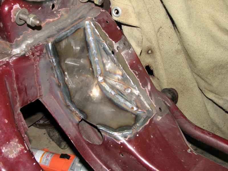
Update: The passenger side frame notch is now boxed back in. I was hoping to do better welding this round, but it didn't turn out the way I'd hoped. Fitment was pretty good, but I still burned through in a couple places and had to do more start-stops than I wanted to prevent that from happening. If I've ever given anyone crap about their welds, I apologize as I still have a lot to learn about and need practice. Here are some pics:


I spent most of the weekend with family, but got a little done on Friday. At first I was going to get the engine on the hoist so I could pull the rear cover, but just prior to getting it in the air I decided I may as well do a test fit to see if my frame notches were going to work out. So in she went.


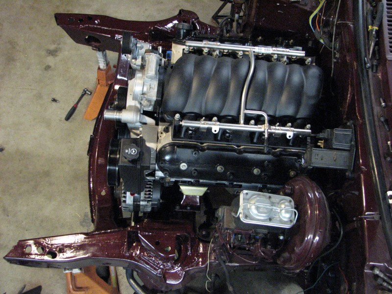
The frame notches and accessory clearance turned out pretty good. Here is the alternator. I still don't have an alternator bracket and I used my old locating spacers to make the flywheel holder, so had to employ it to get the front spacing right for this mockup. It has just the right amount of clearance radially. I could have gotten away with less clearance in the back though.


Here is the AC mounting bracket trimmed and mounted. I took a little bit off the bottom and there's about 3/8" clearance underneath.


The problem I did run into is the lower rear mounting bolt. It is in line with the lower control arm perch. In the current position, unless I cut into that perch, I can't use the lower rear mounting tab on the compressor. If I was using neutral instead of 1/2" setback adapters, this would probably clear.

So in the pictures above and below, the compressor isn't completely mounted; it's tilted nose up a bit because I haven't cut off the rear mounting tab yet.


I think the clearance to the left and rear of the compressor is perfect, but without the bottom mounting tab I could have gotten away with less notching toward the bottom and kept more material at the inside corner of my notch. Maybe if I had three or four frames and a whole bunch of time, I could get it perfect, but for a one-shot thing, I think I did okay.
Overall I am satisfied. I do wonder if I couldn't notch out the LCA perch to get enough room for that mounting tab though. I'm not sure if it's worth it to get full four point mounting of the compressor. The front two and rear upper is probably enough.
The frame notches and accessory clearance turned out pretty good. Here is the alternator. I still don't have an alternator bracket and I used my old locating spacers to make the flywheel holder, so had to employ it to get the front spacing right for this mockup. It has just the right amount of clearance radially. I could have gotten away with less clearance in the back though.
Here is the AC mounting bracket trimmed and mounted. I took a little bit off the bottom and there's about 3/8" clearance underneath.
The problem I did run into is the lower rear mounting bolt. It is in line with the lower control arm perch. In the current position, unless I cut into that perch, I can't use the lower rear mounting tab on the compressor. If I was using neutral instead of 1/2" setback adapters, this would probably clear.
So in the pictures above and below, the compressor isn't completely mounted; it's tilted nose up a bit because I haven't cut off the rear mounting tab yet.
I think the clearance to the left and rear of the compressor is perfect, but without the bottom mounting tab I could have gotten away with less notching toward the bottom and kept more material at the inside corner of my notch. Maybe if I had three or four frames and a whole bunch of time, I could get it perfect, but for a one-shot thing, I think I did okay.
Overall I am satisfied. I do wonder if I couldn't notch out the LCA perch to get enough room for that mounting tab though. I'm not sure if it's worth it to get full four point mounting of the compressor. The front two and rear upper is probably enough.
05-20-2013 | 12:27 PM
#14
And the result:
The first thing to do was a lingering need to remove the lower rear A/C compressor mounting boss.

Once that was done I was able to bolt it on and mock up the rest of the FEAD. I also remounted the evaporator case to get an overall picture of what the engine bay will eventually look like. Here are some shots from around the engine.
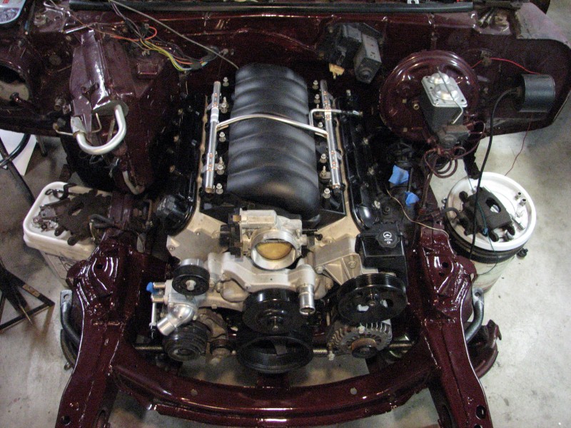


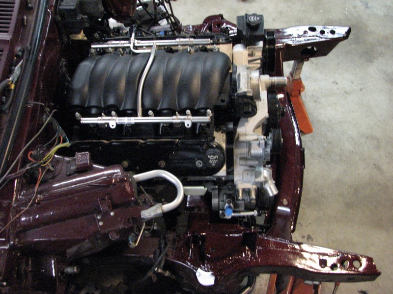
Once that was done I was able to bolt it on and mock up the rest of the FEAD. I also remounted the evaporator case to get an overall picture of what the engine bay will eventually look like. Here are some shots from around the engine.
05-20-2013 | 02:29 PM
#20

Banned
Joined: Sep 2007
Posts: 25
Likes: 1
From: Middle of nowhere
It's really not as bad as it sounds, after trying to find a way then make my own brackets and that new compressor I was going to buy anyway. It comes down to how valuable your time is and if you have the ability to make your own. I know they aren't for everyone but it's geared more towards a plug and play solution. 