
1970 Bug Mid Engine (engine build pg15)
 01-21-2015, 07:54 AM
#281

I was thinking a round bar hood tip to give the front the original shape back, with still having functional air moving through it. (mesh)
 01-21-2015, 04:07 PM
#283

Thanks guys!
You know I never even thought of replacing the cut out section with mesh... Its too bad I already threw the nose away. That would have made it a lot easier. I have a sheet of mesh left that might be big enough to fit.
My other thought was to round the nose of to make it look like a factory nose, just shorter. It would be a lot of work. The hood being pretty much round makes panel making horrible. Too many curves!
02-04-2015, 04:27 PM
#284
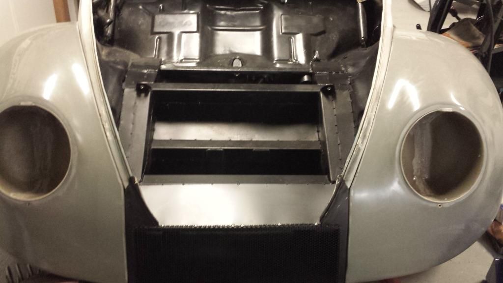
Finally got around to getting more metal. And now the boxing of the front is done! Moving back to the engine compartment next to finish boxing it off. Then finally to the rear end. I have ordered my gauges and they should be here next week! Cams, balance shaft delete, and the rest of my engine parts should be here next week as well. Engine wise I am waiting on my head to get ported and that is about it!
02-10-2015, 01:40 PM
#285
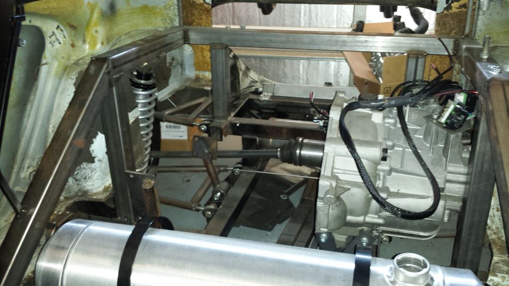
Slowly picking away at this thing. The front is all done now besides paint and smoothing. I started working on the engine compartment again. Got the floor section under the gas tank done. Also mounted the battery mount. I think tonight I will move on the the rear of the car and finish boxing all that in. If not, I am going to pull the engine and trans out so I can get started on them.
The engine build is next. My rotating assembly is currently getting balanced. The rest of my internal parts should be here by the end of the week. I might build the short block over the weekend. We will see.. All I need for the engine now is to get the head CNC ported.
Cam specs I ended up going with: 216 and 218 duration @ .050 and .440 and .436 lift. Now this is small when comparing it to a LS engine but at the same time, it is big for a 2.2 liter. Should turn a good 8000 rpms! Stock cam specs for a comparison: 198 and 193 duration @ .050 and .393 lift.
Battery tray
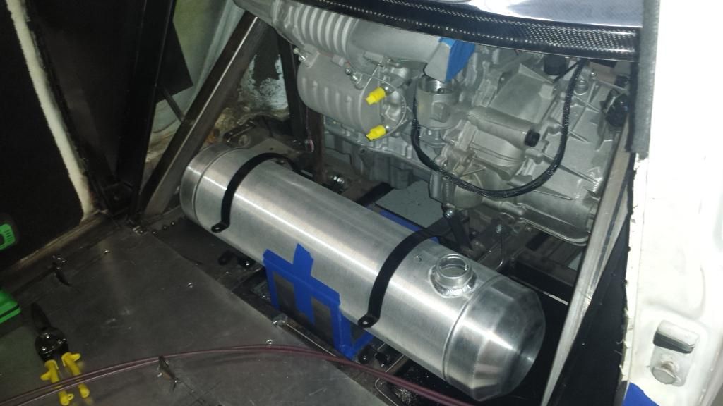
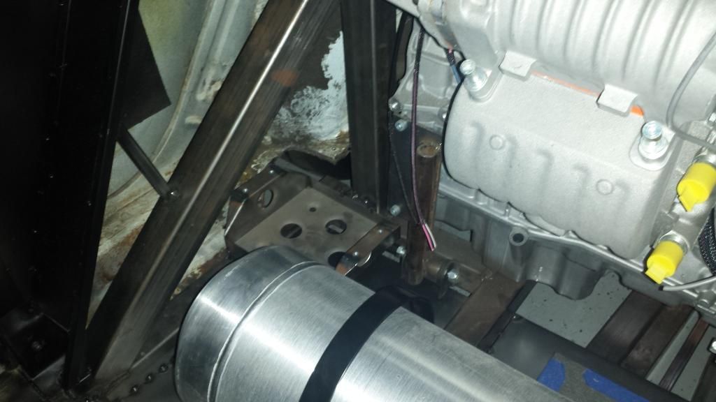
Gas tank has been moved closer to the seats and the floor has been added under it.
The engine build is next. My rotating assembly is currently getting balanced. The rest of my internal parts should be here by the end of the week. I might build the short block over the weekend. We will see.. All I need for the engine now is to get the head CNC ported.
Cam specs I ended up going with: 216 and 218 duration @ .050 and .440 and .436 lift. Now this is small when comparing it to a LS engine but at the same time, it is big for a 2.2 liter. Should turn a good 8000 rpms! Stock cam specs for a comparison: 198 and 193 duration @ .050 and .393 lift.
Battery tray
Gas tank has been moved closer to the seats and the floor has been added under it.
02-14-2015, 03:41 PM
#286
More parts have arrived! Gauges are here. Rotating assembly is back from being balanced. Engine will be getting built to the point of a short block next week. Head is out getting CNC ported and that is that last thing I am waiting for to finish the engine.
The gauges were a nightmare to get in. I got these precut holders for the gauges (green part in the pictures). They were not even close to the right size for the gauges. I knew the speedo wasn't going to fit but none of them fit. Not only was the hole to small, but they were all too close together. All the bezels were more then touching. So after a hour of ovaling the holes, I got it all to fit!
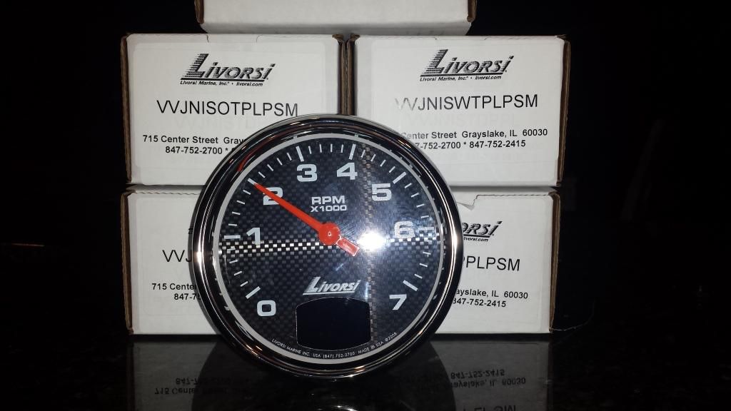
Gauges
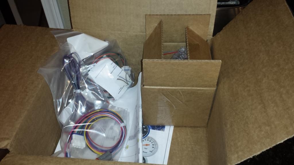
Gauge parts including a 100 page book on how to program them. They are CAN Bus gauges
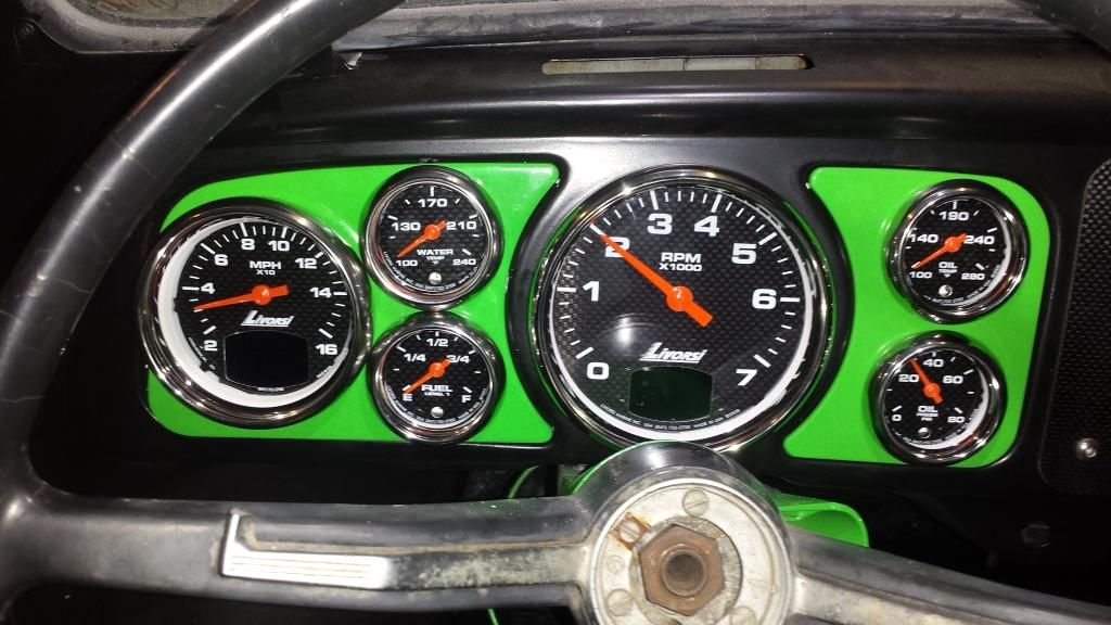
Everything in place and looking good (besides the steering wheel)
The gauges were a nightmare to get in. I got these precut holders for the gauges (green part in the pictures). They were not even close to the right size for the gauges. I knew the speedo wasn't going to fit but none of them fit. Not only was the hole to small, but they were all too close together. All the bezels were more then touching. So after a hour of ovaling the holes, I got it all to fit!
Gauges
Gauge parts including a 100 page book on how to program them. They are CAN Bus gauges
Everything in place and looking good (besides the steering wheel)


 02-16-2015, 04:24 PM
#289
Andrew -
I was wanting the 18 MPH speedo but they didn't make one. I mean keeping it under 20 MPH is going to be hard enough...
Big Ed -
This is going to be my daily driver! Well, by daily I mean only if the weather is good enough. I plan on being able to drive to the track, do some laps, and drive home with it. I figure why build a car if you can't enjoy it on the streets. A full on race car would be cool, but I just wouldn't get as much fun out of it.
02-27-2015, 12:48 AM
#291
Registered User

Join Date: Sep 2014
Posts: 3
Likes: 0
Received 0 Likes
on
0 Posts
If you put a 2" plastic lip under the rad, a lot of air will be forced through the rad. You can put a stock nose on, leave the area behind it open but sealed around the rad so any air grabbed by the lip is forced through the rad. Works like a charm, I've verified it a few different ways. Unless you don't mind a modified front end look, then your concept will also work. Just wanted you to know if you wanted to keep it more stock looking it's totally doable.
02-27-2015, 07:09 PM
#292
Its been a while since I posted an update so I figured its time. Not much has been done except for some welding. I have the engine back out so I can get to all the places I couldn't with the engine in. Lots of welding in my future.... I am to the point where mostly all my mock up stuff is done and time to disassemble the entire car. Then more welding... After welding is paint. After paint, it is all going back together for the final product.
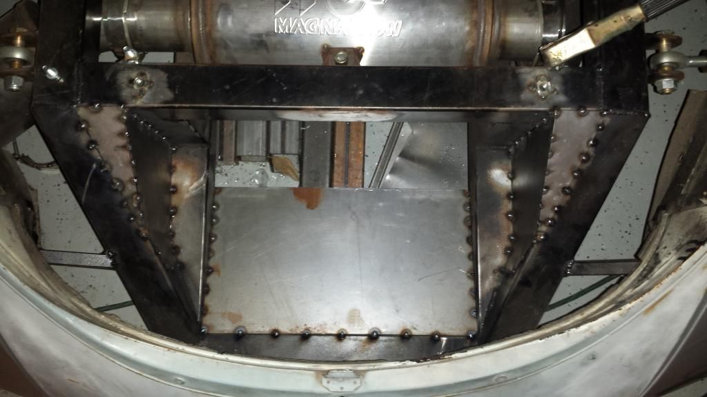
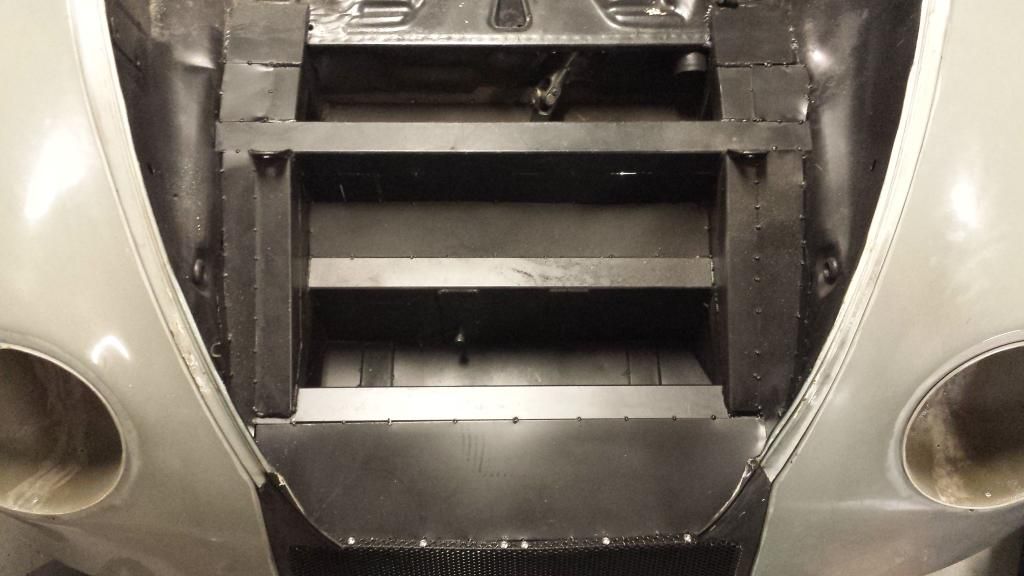
More ducting made. One more to go!
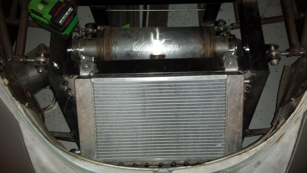
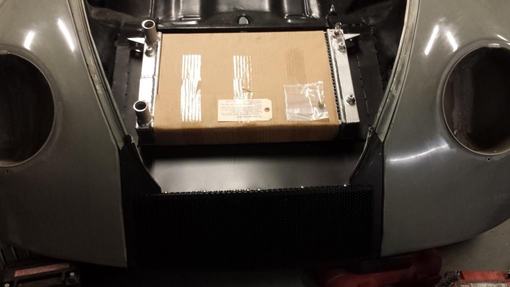
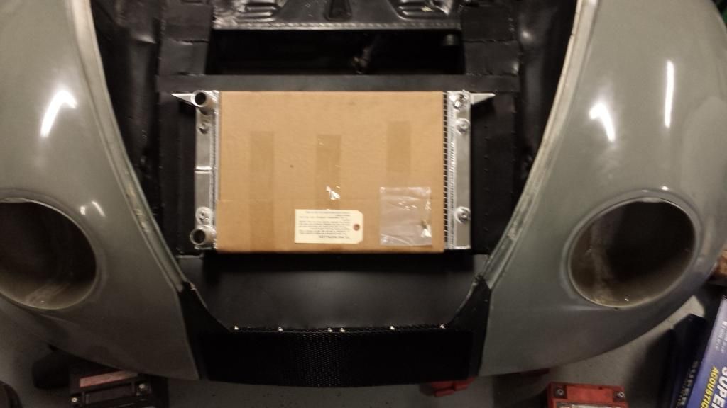
The cooler back in
More ducting made. One more to go!
The cooler back in
02-27-2015, 07:22 PM
#293
If you put a 2" plastic lip under the rad, a lot of air will be forced through the rad. You can put a stock nose on, leave the area behind it open but sealed around the rad so any air grabbed by the lip is forced through the rad. Works like a charm, I've verified it a few different ways. Unless you don't mind a modified front end look, then your concept will also work. Just wanted you to know if you wanted to keep it more stock looking it's totally doable.
02-27-2015, 10:55 PM
#294
If you put a 2" plastic lip under the rad, a lot of air will be forced through the rad. You can put a stock nose on, leave the area behind it open but sealed around the rad so any air grabbed by the lip is forced through the rad. Works like a charm, I've verified it a few different ways. Unless you don't mind a modified front end look, then your concept will also work. Just wanted you to know if you wanted to keep it more stock looking it's totally doable.
 03-01-2015, 01:53 PM
#295
I know it doesn't look good.... It is something that bothers me but not a whole lot. As long as it functions for now, I am good with it. I am getting a fiberglass hood after it is up running and driveable. So for now, this is my test hood. Keep the comments coming so I can get more opinions!

 03-11-2015, 02:30 PM
#298
It is finally time to start the engine build! Sorry it isn't a LS but it is still going to be a blast. For all of you who know how to build a LS, this build is a bit different. I have built over 200 Ecotecs so this one should be simple.
Lets begin!
Step 1 - Remove mock up engine from car
Step 2 - Locate good engine. Disassemble and clean.
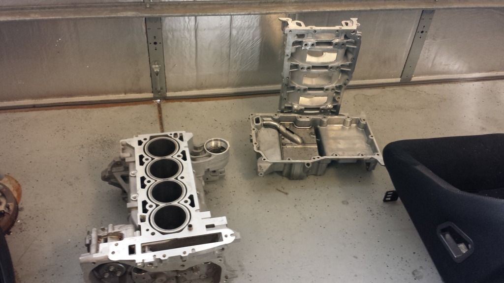
Step 3 - Get good parts to put in the engine. Don't want to do this twice.
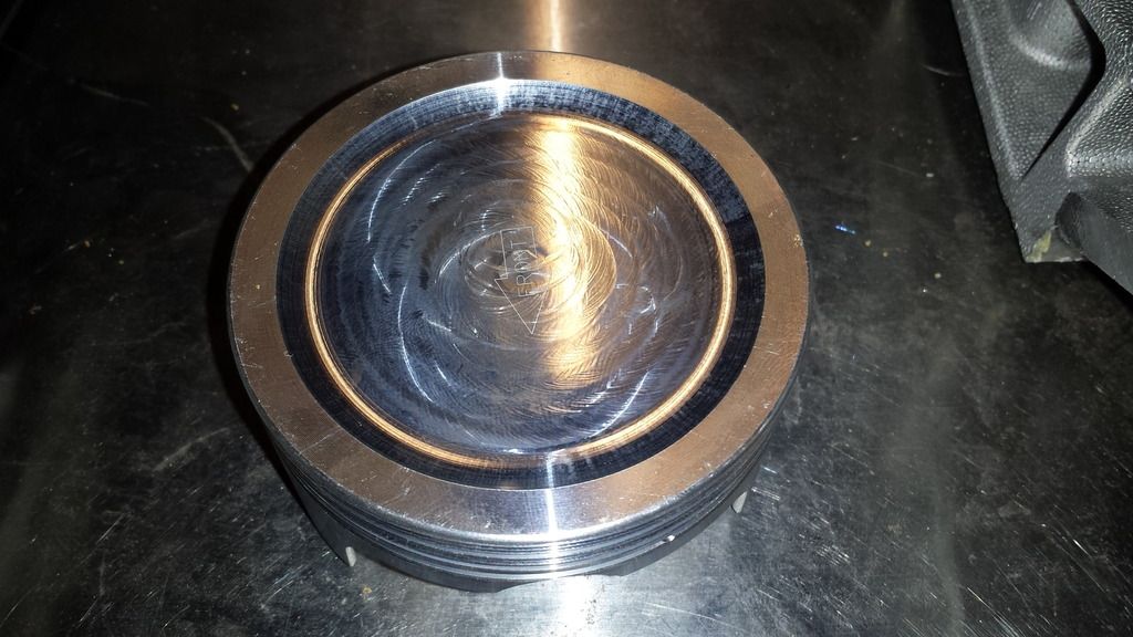
JE Pistons 9:1 compression
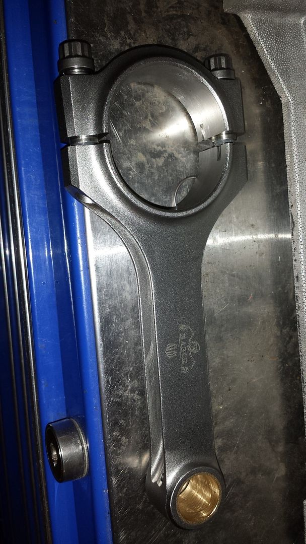
Eagle H-beam rods connecting to the stock crank
Step 4 - Measure, measure, and then measure some more. Check the bore, piston diameter, crank specs, and so on. Good accurate tools are a must as this is the most important part.
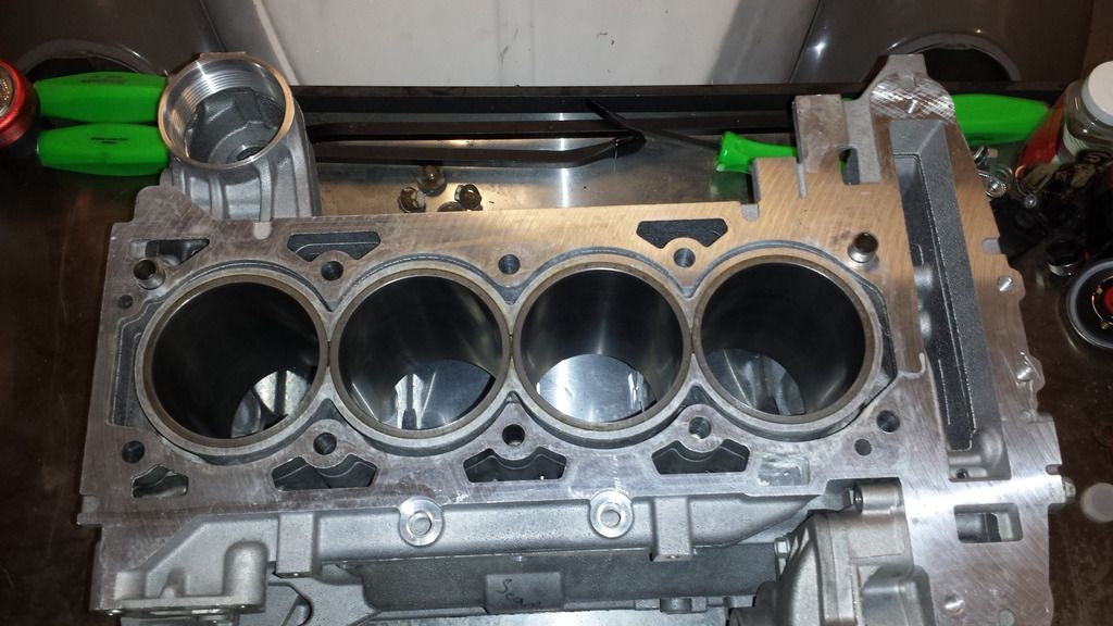
My block was .0015 out of round and .001 bigger then it should be on the bore. No good. So it went away to the machine shop to get fixed. My crank came out to stock specs but I did not like its finish as there were a lot of deep scratches. So the crank went in to get turned. After all that, the rotating assembly was balanced.
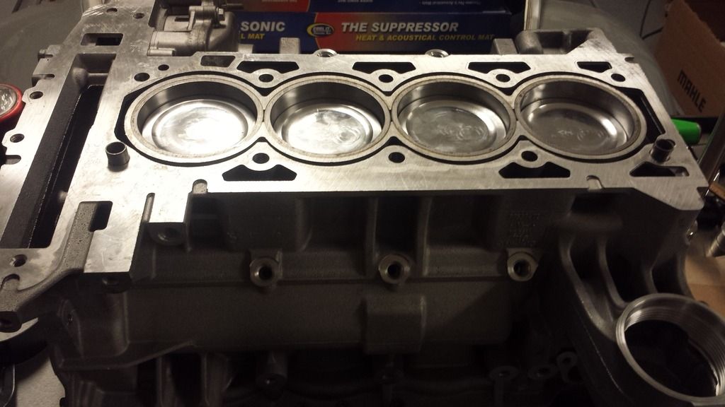
Step 5 - Assemble pistons and hang the rods. Checked ring gap and set to where it needs to be. Make sure to get the rings going the right direction and facing the right way!
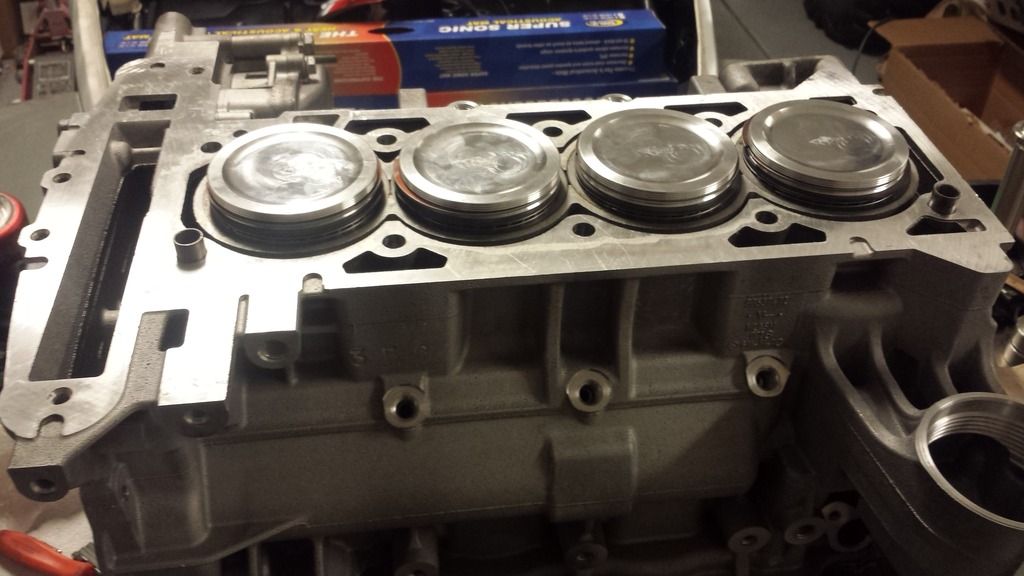
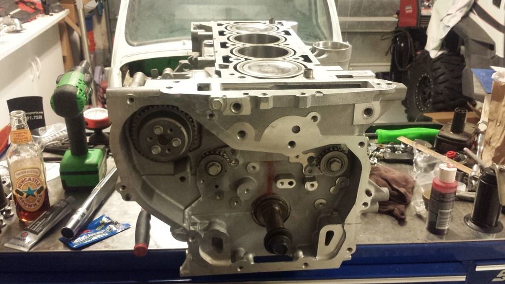
Step 6 - Here is where the Ecotec is different from the LS. Pistons go in first. Then the crank.
Step 7 - Flip engine over and install crank. Don't forget the assembly lube!
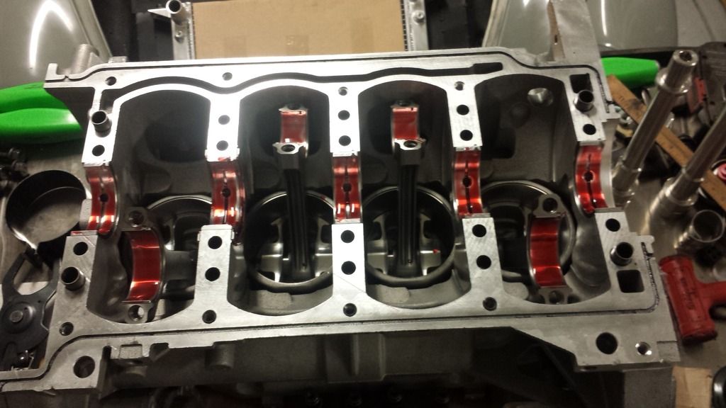
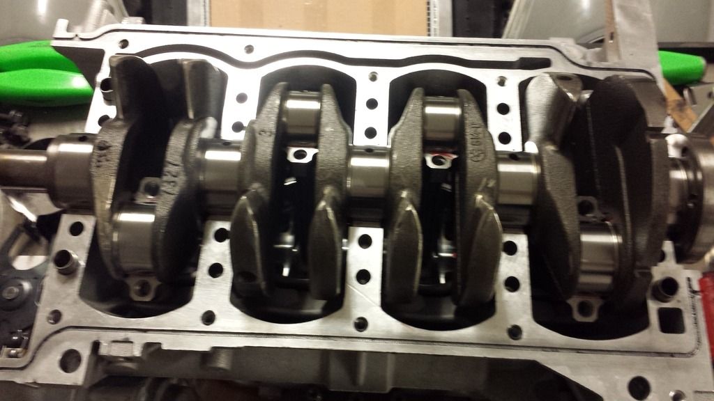
Torque rods after the crank is in.
Step 8 - Install the bottom engine half. More assembly lube and a layer of silicon around the case to seal it off. Grey seems to hold up better then black silicon.
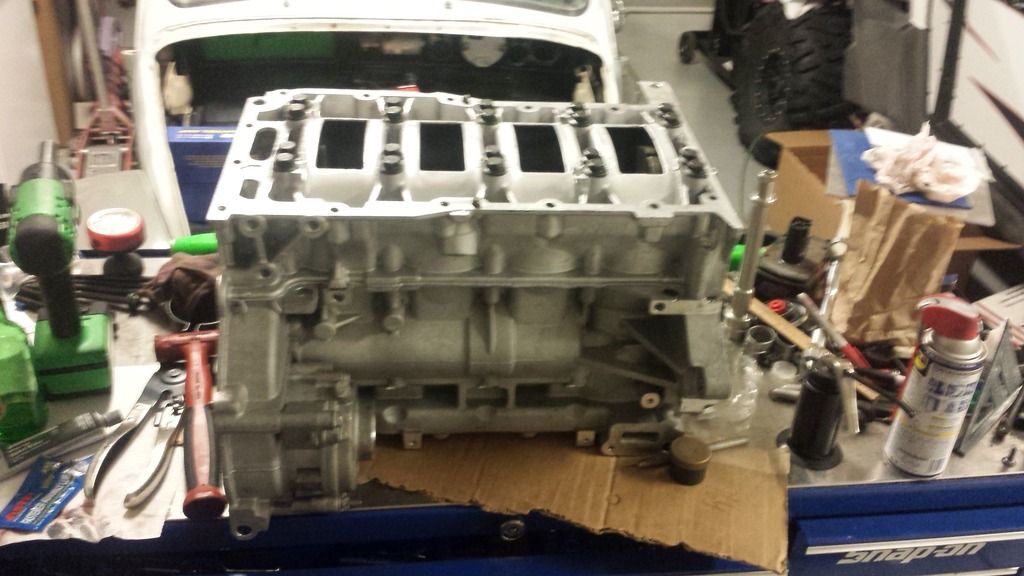
There are a total of 30 bolts holding the block together. Make sure to torque them in the right sequence. After it is all torqued, spin the crank to make sure it rotates smoothly.
Step 9 - Time to put in the neutral balance shafts. This is yet another thing the LS engines do not have. Note the stock balance shaft on the left compared to the neutral balance shaft on the right. The stock ones rob power but help make the engine feel smooth.
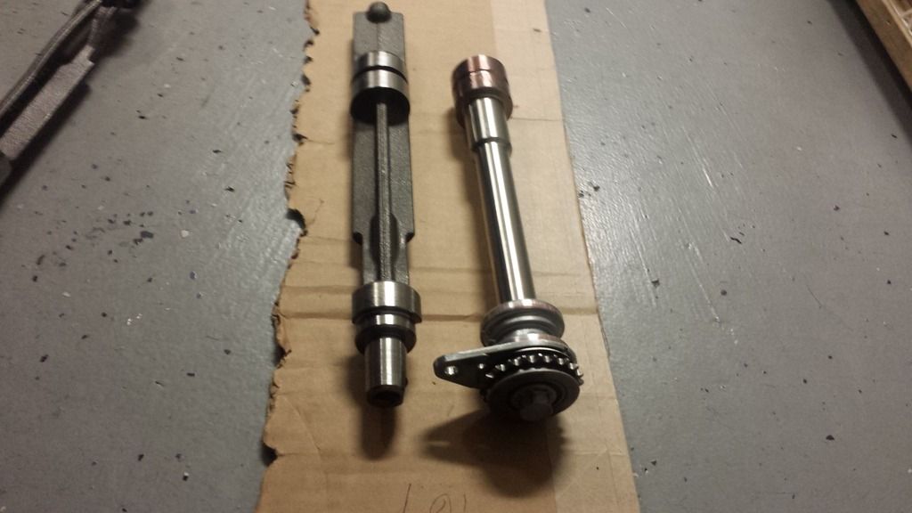
Neutral balance shafts installed. Called it a night at this point. More to come!
Lets begin!
Step 1 - Remove mock up engine from car
Step 2 - Locate good engine. Disassemble and clean.
Step 3 - Get good parts to put in the engine. Don't want to do this twice.
JE Pistons 9:1 compression
Eagle H-beam rods connecting to the stock crank
Step 4 - Measure, measure, and then measure some more. Check the bore, piston diameter, crank specs, and so on. Good accurate tools are a must as this is the most important part.
My block was .0015 out of round and .001 bigger then it should be on the bore. No good. So it went away to the machine shop to get fixed. My crank came out to stock specs but I did not like its finish as there were a lot of deep scratches. So the crank went in to get turned. After all that, the rotating assembly was balanced.
Step 5 - Assemble pistons and hang the rods. Checked ring gap and set to where it needs to be. Make sure to get the rings going the right direction and facing the right way!
Step 6 - Here is where the Ecotec is different from the LS. Pistons go in first. Then the crank.
Step 7 - Flip engine over and install crank. Don't forget the assembly lube!
Torque rods after the crank is in.
Step 8 - Install the bottom engine half. More assembly lube and a layer of silicon around the case to seal it off. Grey seems to hold up better then black silicon.
There are a total of 30 bolts holding the block together. Make sure to torque them in the right sequence. After it is all torqued, spin the crank to make sure it rotates smoothly.
Step 9 - Time to put in the neutral balance shafts. This is yet another thing the LS engines do not have. Note the stock balance shaft on the left compared to the neutral balance shaft on the right. The stock ones rob power but help make the engine feel smooth.
Neutral balance shafts installed. Called it a night at this point. More to come!
03-12-2015, 09:30 AM
#299

Looking good. You will inspire someone to copy this build. That says alot IMB
