
1967 Cougar build (over 500 pictures and videos)
 04-26-2015, 03:36 PM
#361
TECH Senior Member
Thread Starter
iTrader: (7)

Friday I got out to the garage and decided to tackle the engine mounts. I really couldn't do much else until that was all figured out. The Mod motor mounts were a total bust. They are designed for a much wider engine bay and the studs basically hit the area on the lower shock tower where the stock engine mounts bolt up.
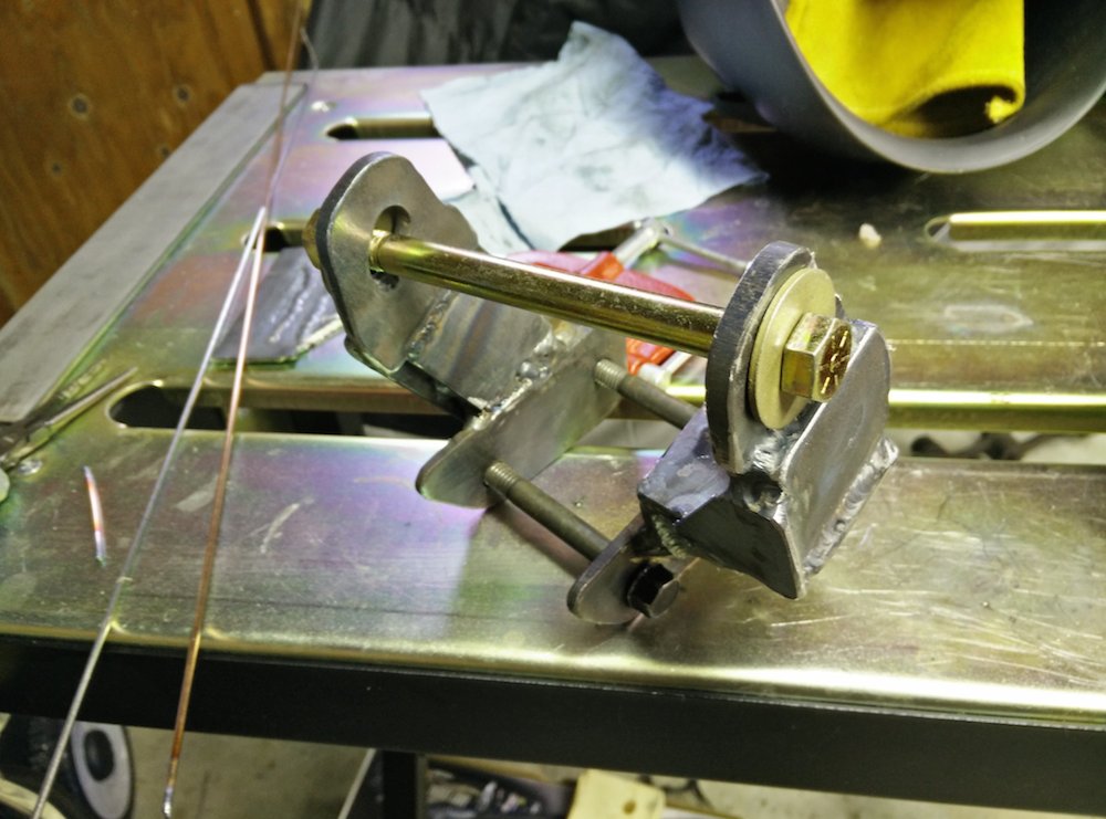
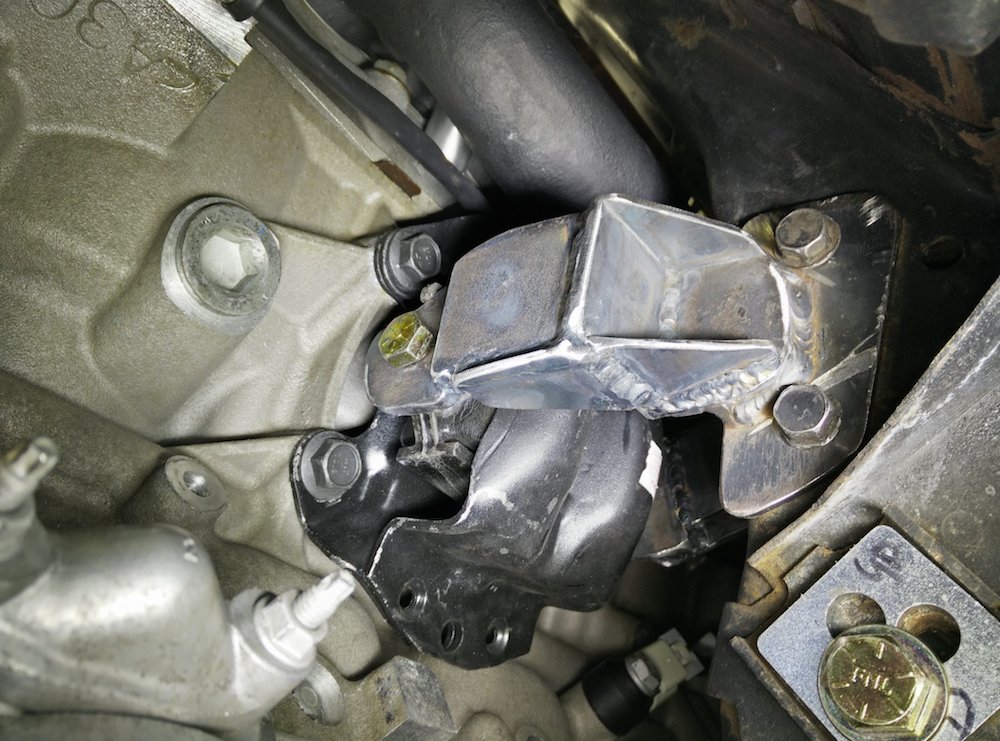
After much thought, I decided to get brave and cut up the mounts that were already made. I reused the plates that mounted to the chassis, cut the tops off that bolted to the engine mounts, then basically reconnected the dots with plate. They aren't super pretty but I think they will work nicely.
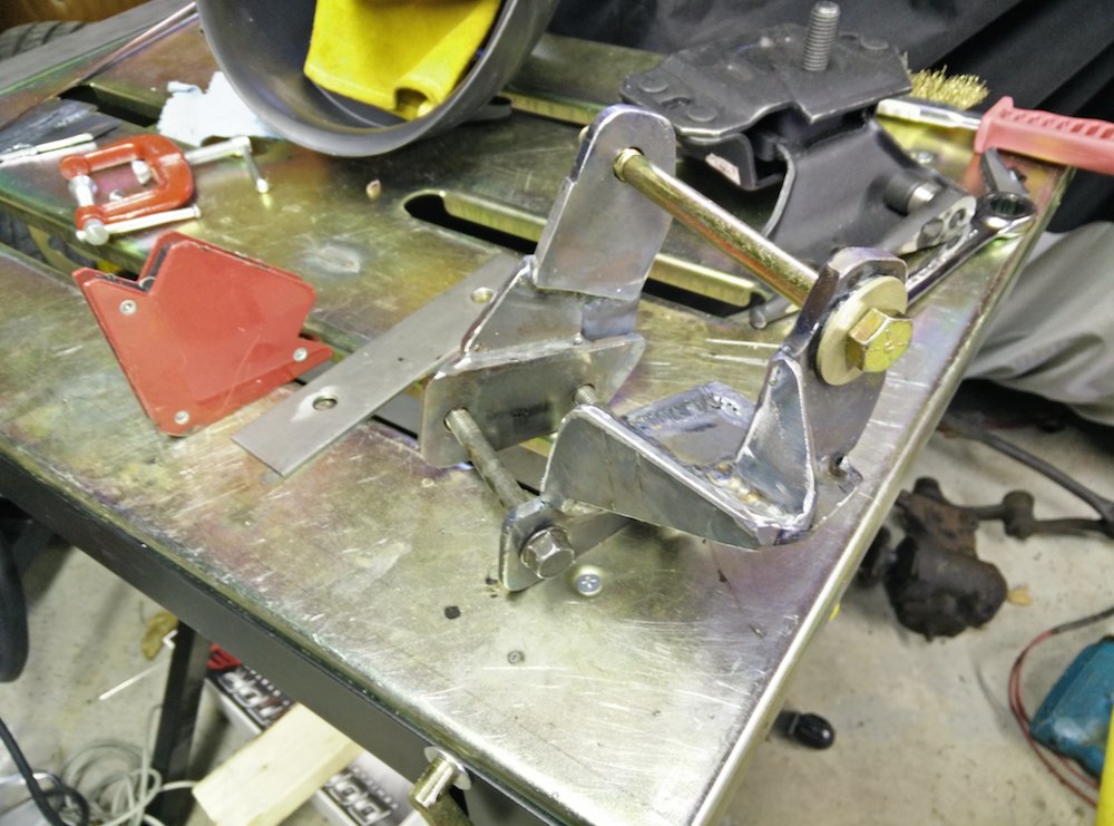
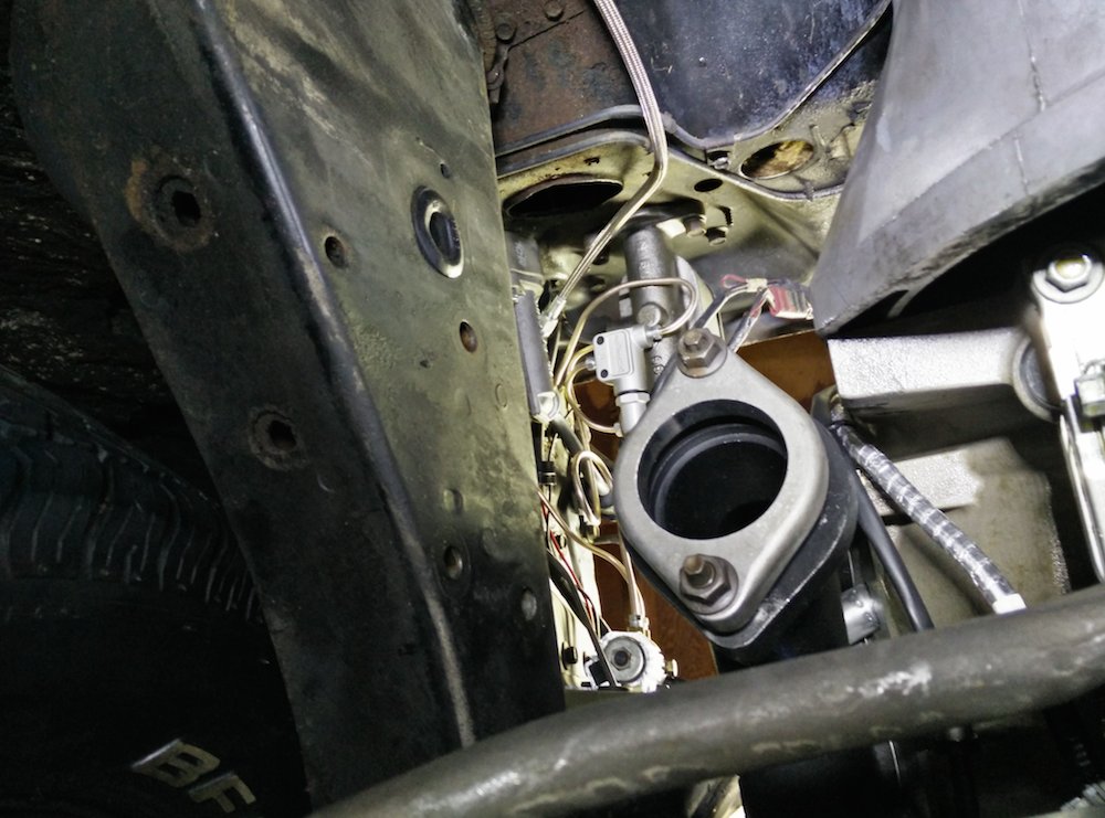
Here is the driver's side mount:
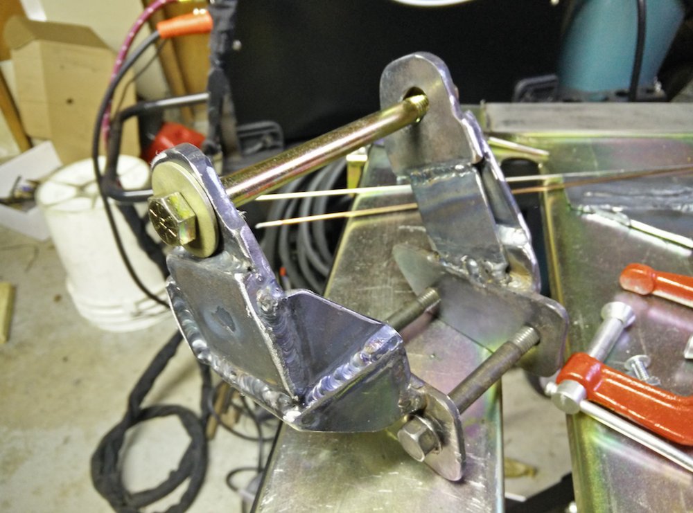
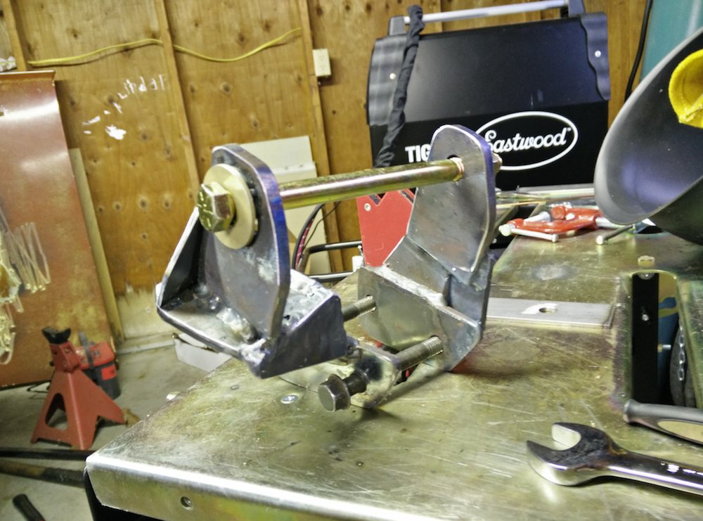
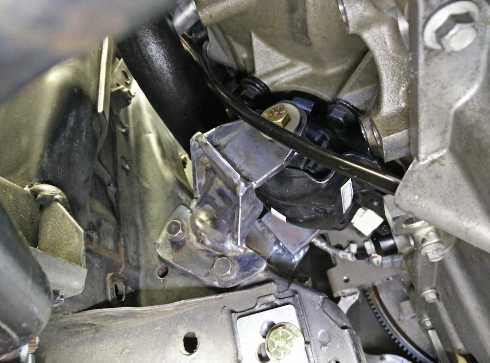
Here is the passenger side mount:
The driver's side inner tie rod clearance was right on.
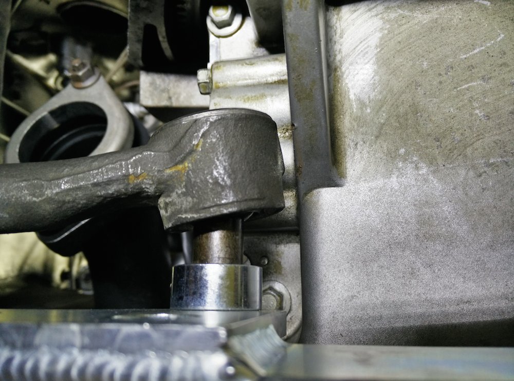
With the TCP rack installed, there is also a ton of room for exhaust!
The passenger side inner tie rod clearance was just a little bit off, but a little grinding on the rib gave me the air gap that I needed. You only need a little gap there since the rack will only be in that position when parking.
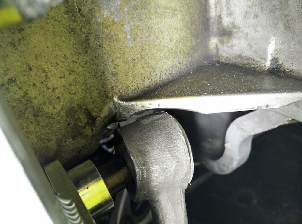
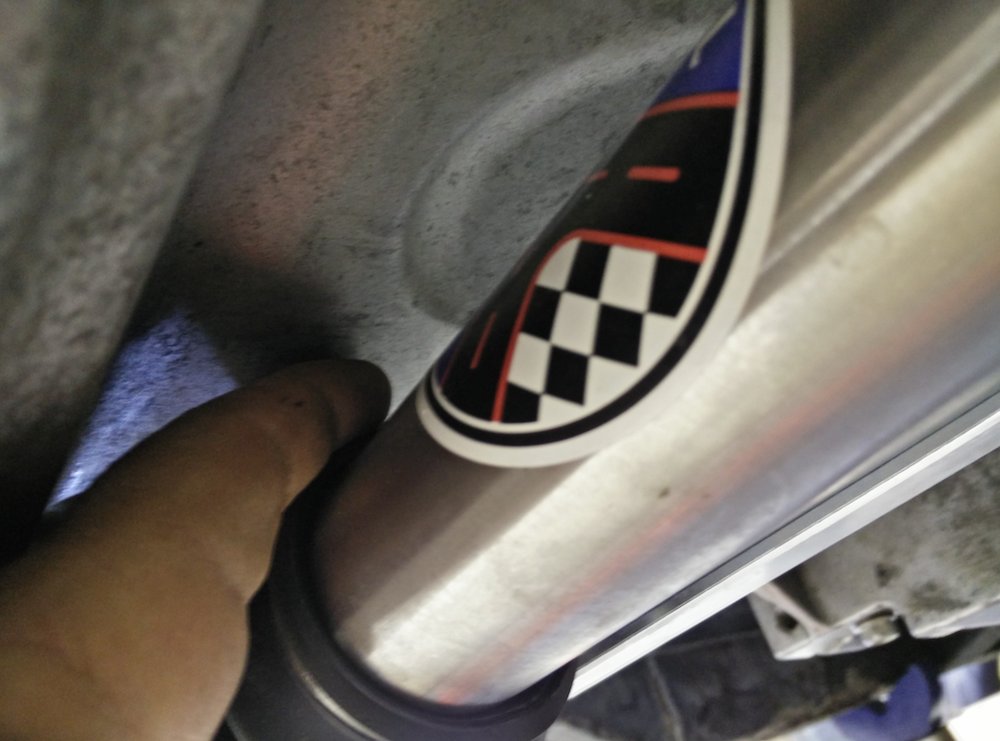
There is also about a finger width of room between the pan and the top of the rack and at no point do the rubber boots touch the pan.
To be continued...
Andrew
After much thought, I decided to get brave and cut up the mounts that were already made. I reused the plates that mounted to the chassis, cut the tops off that bolted to the engine mounts, then basically reconnected the dots with plate. They aren't super pretty but I think they will work nicely.
Here is the driver's side mount:
Here is the passenger side mount:
The driver's side inner tie rod clearance was right on.
With the TCP rack installed, there is also a ton of room for exhaust!
The passenger side inner tie rod clearance was just a little bit off, but a little grinding on the rib gave me the air gap that I needed. You only need a little gap there since the rack will only be in that position when parking.
There is also about a finger width of room between the pan and the top of the rack and at no point do the rubber boots touch the pan.
To be continued...
Andrew
 04-26-2015, 03:50 PM
#362
TECH Senior Member
Thread Starter
iTrader: (7)
Here is the driver's side mount installed:
Here is the passenger side mount installed:
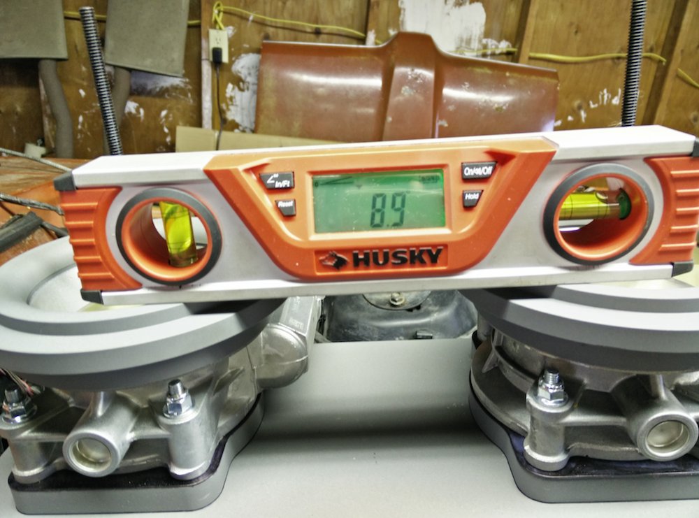
The engine is level with respect to the chassis (left to right), and front to back the engine is a 3.7* relative to the chassis at the rocker by the pinch weld (chassis is at 5.2* with the front on jack stands and engine is at 8.9*, hence 8.9 - 5.2 = 3.7)
It's great to see the engine installed knowing that it is solidly anchored where it is supped to be (ignore the backwards manifold...LOL)
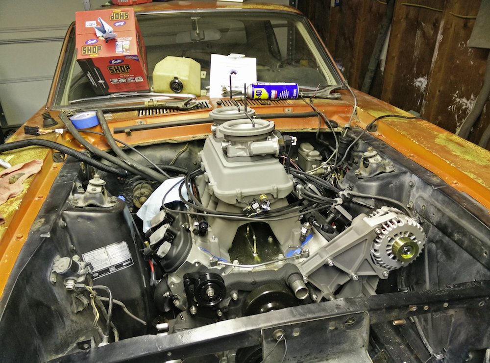
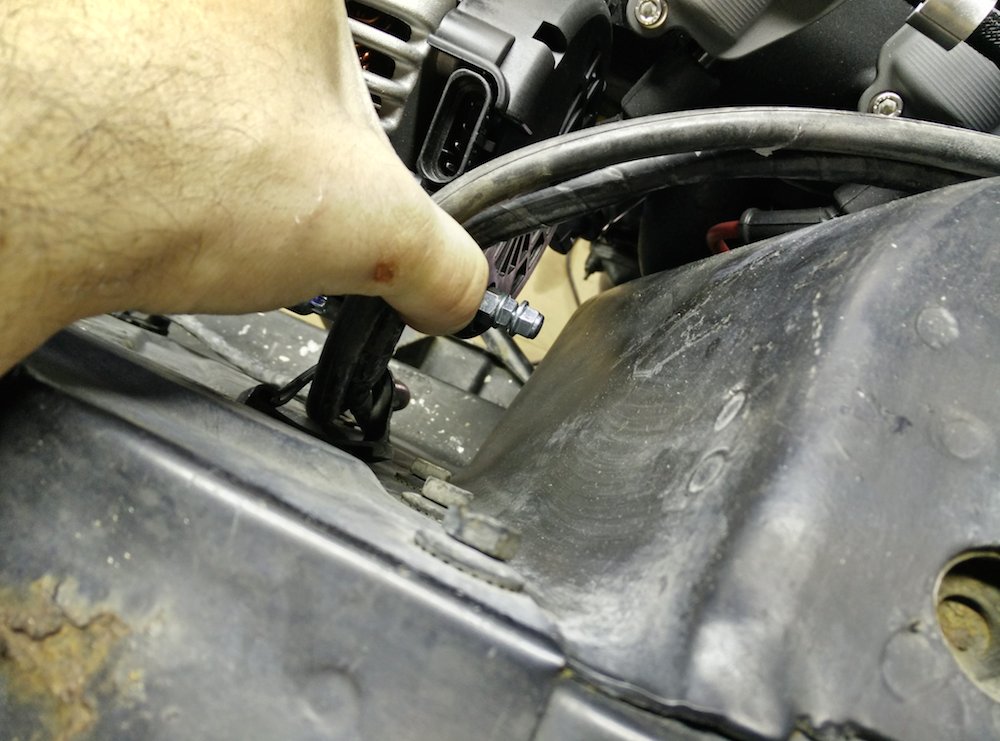
Here are a few critical areas of clearance. With the alternator hanging off high and to the driver's side (C5/C6 Corvette placement), there is about an inch of clearance between the front of the shock tower and the alternator main output stud. I could run a different alternator mount, but there is no sense in changing it now. Besides, with the alternator up high there is plenty of room to turn the manifolds around, if any of you catch my drift...LOL
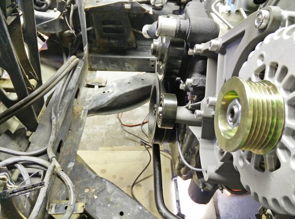
There alternator is also a couple of inches away from the side of the engine bay:
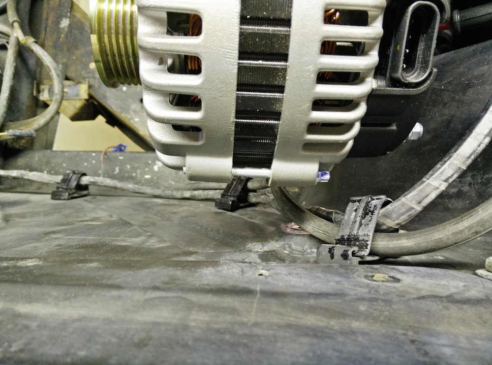
As far as front to back, the sway bar is right at the center and about an inch above the sway bar:
Sad that I have to yank it all out...LOL
Andrew
Here is the passenger side mount installed:
The engine is level with respect to the chassis (left to right), and front to back the engine is a 3.7* relative to the chassis at the rocker by the pinch weld (chassis is at 5.2* with the front on jack stands and engine is at 8.9*, hence 8.9 - 5.2 = 3.7)
It's great to see the engine installed knowing that it is solidly anchored where it is supped to be (ignore the backwards manifold...LOL)
Here are a few critical areas of clearance. With the alternator hanging off high and to the driver's side (C5/C6 Corvette placement), there is about an inch of clearance between the front of the shock tower and the alternator main output stud. I could run a different alternator mount, but there is no sense in changing it now. Besides, with the alternator up high there is plenty of room to turn the manifolds around, if any of you catch my drift...LOL
There alternator is also a couple of inches away from the side of the engine bay:
As far as front to back, the sway bar is right at the center and about an inch above the sway bar:
Sad that I have to yank it all out...LOL
Andrew
04-27-2015, 03:18 AM
#363


Looks great Andrew. You attention to details will set this build appart once conplete.
04-28-2015, 07:00 AM
#366

Freak'in Awsum !!!!!!!!
04-28-2015, 09:52 AM
#367
TECH Senior Member
Thread Starter
iTrader: (7)
Here is the first video that I took during the evening. The first step when working with the Dominator ECU is to perform a TPS autoset. This involves having the laptop hooked to the ECU, selecting the TPS autoset command from the menu, and cycling the pedal through its full range of motion twice. Once that is done, the ECU has full control of the dual DBW throttle bodies.
More to come.
Andrew
More to come.
Andrew

The following users liked this post:
Saber-1 (10-25-2023)

 04-28-2015, 08:06 PM
#372
See you on the maiden voyage in the Dells.....LOL.....2 1/2 weeks...........
04-28-2015, 08:13 PM
#373
TECH Senior Member
Thread Starter
iTrader: (7)
Ken, I really need to thank you again, without your help this pile wouldn't be running right now!
Andrew
04-29-2015, 06:37 AM
#374
Bring the GTO..................
 04-29-2015, 09:56 PM
#377
