When you click on links to various merchants on this site and make a purchase, this can result in this site earning a commission. Affiliate programs and affiliations include, but are not limited to, the eBay Partner Network.
so i have a 71 chevelle with a carb LS engine.question on wiring my alternator. i have a alt with 4 pin harness plug. from what i understand i need to run a switched 12v with a resistor to the B terminal. for the output wire can i just run it to the horn relay? thats where the original wire went.
with my old ext volt regulator unplugged can i connect that brown#4 wire to anything to keep idiot light working?
thanks for any help! cant wait to b able to fire up this motor
i have searched alot for answer but find just a ton of different answer. i hope someone here has same or close situation as me.
Hook the OEM gen light wire to the I terminal and a short wire from the S terminal to the battery stud of the alternator. This made the gen light function correctly on the LS3 swap into a 1968 Chevelle that I did a couple of months ago.'
I am going through this now. I have a DR44G with a 4 pin regulator. When tested at O'reillys the output is 14.6V. I have an indicator light (idiot light) in the dash wired to switched 12V and then to the L terminal. With engine running, output is 13.8V. Next I'm connecting the sense terminal to the 12V power from battery to the starter. I think that will vary the alternator output dependent on load.
It should now be obvious how to wire a CS-series / 4-terminal alternator, but just to summarize:
PLFS-type
Mandatory connections:
1) Connect the alternator output terminal (B or Bat) to the electrical system's main distribution point (bus bar, junction, etc.) Less optimal alternatives that will work include connecting it to the battery + terminal or a terminal on the starter motor that also connects to the battery + terminal.
2) Connect the L terminal to a source of switched ignition power through an indicator lamp wired in series. Also connect a 50 Ohm resistor in parallel with the indicator lamp so that if the bulb burns out, the alternator will still be excited.
3) Ensure there is a good ground connection between the bare alternator case, the mounting bracketry and the engine block/heads and/or install a dedicated ground wire from the engine block to the alternator's ground terminal (if it has one).
Crucial connections:
4) Strictly speaking, the alternator will work with only the three wiring connections listed above, but I consider it crucial for good performance that you also wire up the remote voltage sensing terminal. To do this, connect the S terminal to the vehicle electrical system's main power distribution point (bus bar, main switch, fuse panel, etc.). If the S remote voltage sensing terminal is not connected, the voltage regulator will revert to internal sensing of the alternator output terminal voltage - with all the limitations that brings. You will see some alternators wired with a short jumper wire from the S terminal directly to the battery connection at the back of the alternators, but this is neither the proper method for remote voltage sensing nor necessary for internal sensing - do it properly or leave it out.
Optional connections:
5) If you have an external device such as a tachometer, hourmeter, or other device, it may be connected to terminal P. Connect the device in the manner specified by the manufacturer of the device.
This is a diagram of such a CS-series, PLFS alternator wired using terminals L, S, and BAT.
The way I understand it, when the sense wire is connected to main 12v in the car and there is a voltage drop, the voltage regulator bumps up the output voltage to compensate.
Last edited by SSSTANG#1; May 25, 2015 at 01:32 PM.
The GMPP LS harnesses only have one wire going to the L terminal.
Like I said, it charges fine at 13.8v with only the L terminal connected. I just want it to work at full potential if that's possible without an input from the factory ECU.
Can you elaborate more on what the S connection actually does?
The GMPP LS harnesses only have one wire going to the L terminal.
I am in the process of doing the wiring on my Cougar and I can easily add the S wire, but I would like to better understand it's purpose.
Andrew
On the LS3 swap into a 1968 Chevelle, without the S wire hooked to the batt terminal, the gen light would stay on with the engine running & the alternator charging.
Thanks guys. This seems like a simple thing to incorporate when installing from scratch. I don't have a Gen light in the dash and all of my gauges will be displayed through the Holley digital dash. I actually have the L terminal wired into an output on the Holley Dominator harness. I have it programmed to energize when the RPM are above 250.
Where would be the best place to run the S terminal? I am thinking of running it to where the main feed comes into the stock fuses on my Cougar. The fuse panel gets power from a main feed from under the hood and it is likely the place where the most voltage drop would occur. Seems like a good spot?
Like I said, it charges fine at 13.8v with only the L terminal connected. I just want it to work at full potential if that's possible without an input from the factory ECU.
On my GTO, my volt meter (Autometer) in the dash reads 14.7v when the engine is running. I have a Corvette alternator.
Thanks guys. This seems like a simple thing to incorporate when installing from scratch. I don't have a Gen light in the dash and all of my gauges will be displayed through the Holley digital dash. I actually have the L terminal wired into an output on the Holley Dominator harness. I have it programmed to energize when the RPM are above 250.
Where would be the best place to run the S terminal? I am thinking of running it to where the main feed comes into the stock fuses on my Cougar. The fuse panel gets power from a main feed from under the hood and it is likely the place where the most voltage drop would occur. Seems like a good spot?
Andrew
The L terminal is wired through a bulb to +12v so when the switch is "on" there is a difference of potential and the bulb lights until the alternator has an output and no difference of potential.
Sounds like a good place for S terminal wire.
Last edited by SSSTANG#1; May 27, 2015 at 06:07 AM.
The L terminal is wired through a bulb to +12v so when the switch is "on" there is a difference of potential and the bulb lights until the alternator has an output and no difference of potential. I read somewhere that constant 12v was not desired.
....
The wire that goes to my L terminal is controlled by the Dominator ECU. It is dead until the engine is running, minimum RPM of 250. I can even program it to shut off when TPS is above a certain %, so there is less drag at WOT....but I probably won't do that. Do you see any issues with that?
The wire that goes to my L terminal is controlled by the Dominator ECU. It is dead until the engine is running, minimum RPM of 250. I can even program it to shut off when TPS is above a certain %, so there is less drag at WOT....but I probably won't do that. Do you see any issues with that?
Andrew
I am, by far, not an expert on operation of this voltage regulator but have been told and read that you only want a momentary 12v on the L terminal to excite the alternator. A constant 12v can or will damage the regulator. On your Dominator output you can enable a secondary deactivation to turn off the 12v so no problem there.
On the LS3 swap into a 1968 Chevelle, without the S wire hooked to the batt terminal, the gen light would stay on with the engine running & the alternator charging.
Russ Kemp
This good to know . Mine light is always on when running . Charges fine . I could not get a answer on why it was doing this . I thought I had a bad regulator . I will add the S wire and see what happens . This has always annoyed me .
So is using a bulb in line for L optional or can I just use 470 ohm resistor? Can I put the wire that goes to my original dummy light into P? It did go into my old external voltage regulator. Can F and S come from fuse panel accessory plug?
On the LS3 swap into a 1968 Chevelle, without the S wire hooked to the batt terminal, the gen light would stay on with the engine running & the alternator charging.
Russ Kemp
Is the L terminal connected to anything?
My L terminal connected to switched 12v through a light in the dash, excites the alternator and the light goes off when alternator starts charging.
When I had the Ford engine and 3G alternator, it was wired identicall to this one and worked fine. If alternator output drops, indicator light comes on due to difference of potential.
At least on this alternator/voltage regulator, I'm hoping the "sense" terminal works off varying 12v.
I may be wrong about the L terminal. Just found this on Yellow Bullet...
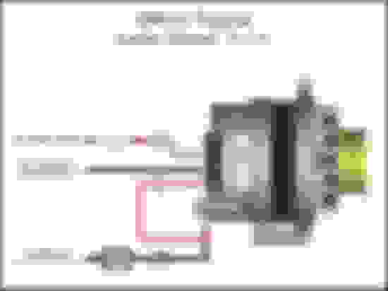
if you have the dr44g truck alt you dont need to wire a resister or bulb in..it will default to 13.8 an then just run the cable from the post back to the batt or kill switch like this pic..i like to run the power up to a batt junction box up front..then power for fuse block,switch panel and starter i pull from that..heres a basic pic to give you a idea..read the holley directions for connecting the ecu to a kill switch..its at the bottom of the pink sheet that came with the ecu..if you dont have it then to save some time heres what it says.
6 Common C5 Corvette Failures and What's Involved In Repairing Them
Slideshow: From wobbling harmonic balancers to failed EBCMs, these are the issues that define long-term C5 ownership and what repairs typically involve.
Retro Modern Bandit Pontiac Trans AM Comes With Burt Reynolds' Autograph
Slideshow: A modern Camaro transformed into a retro icon, this limited-run "Bandit" build blends nostalgia with brute force in a way few revivals manage.
Top 10 Greatest Cadillac V Series Performance Models Ever, Ranked
Slideshow: Cadillac didn't just crash the high-performance luxury vehicle party, it showed up loud, supercharged, and occasionally a little unhinged...
Coachbuilt N2A Anteros Is an LS2-Powered C6 Corvette In Italian Clothes
Slideshow: A one-off sports car that looks like a vintage Italian exotic-but hides a C6 Corvette underneath-just sold for the price of a new mid-engine Corvette.