When you click on links to various merchants on this site and make a purchase, this can result in this site earning a commission. Affiliate programs and affiliations include, but are not limited to, the eBay Partner Network.
Ok - I've started this new thread to figure out a puzzle - I have at least three different 6L80E wiring diagrams and I do not think any of them are correct for the 2014 version. My setups converter is not unlocking.
The 2014 6L80E I'm working with has three wires from the ecm - Brake apply power supply, brake apply signal, and brake apply low reference.
On previous version 6L80E's there is only one wire (that I have found in pinouts), the brake apply signal which takes a constant keyed 12v and no voltage when brake is applied.
Also - previous pinouts of the 6L80E say that there is B+ and keyed 12v - the 2014 I have only found a B+.
Does anyone have or have access to the 16 pin connector pinout on the 6L80E trans? And have any experience in wiring the brake signal to the ecm?
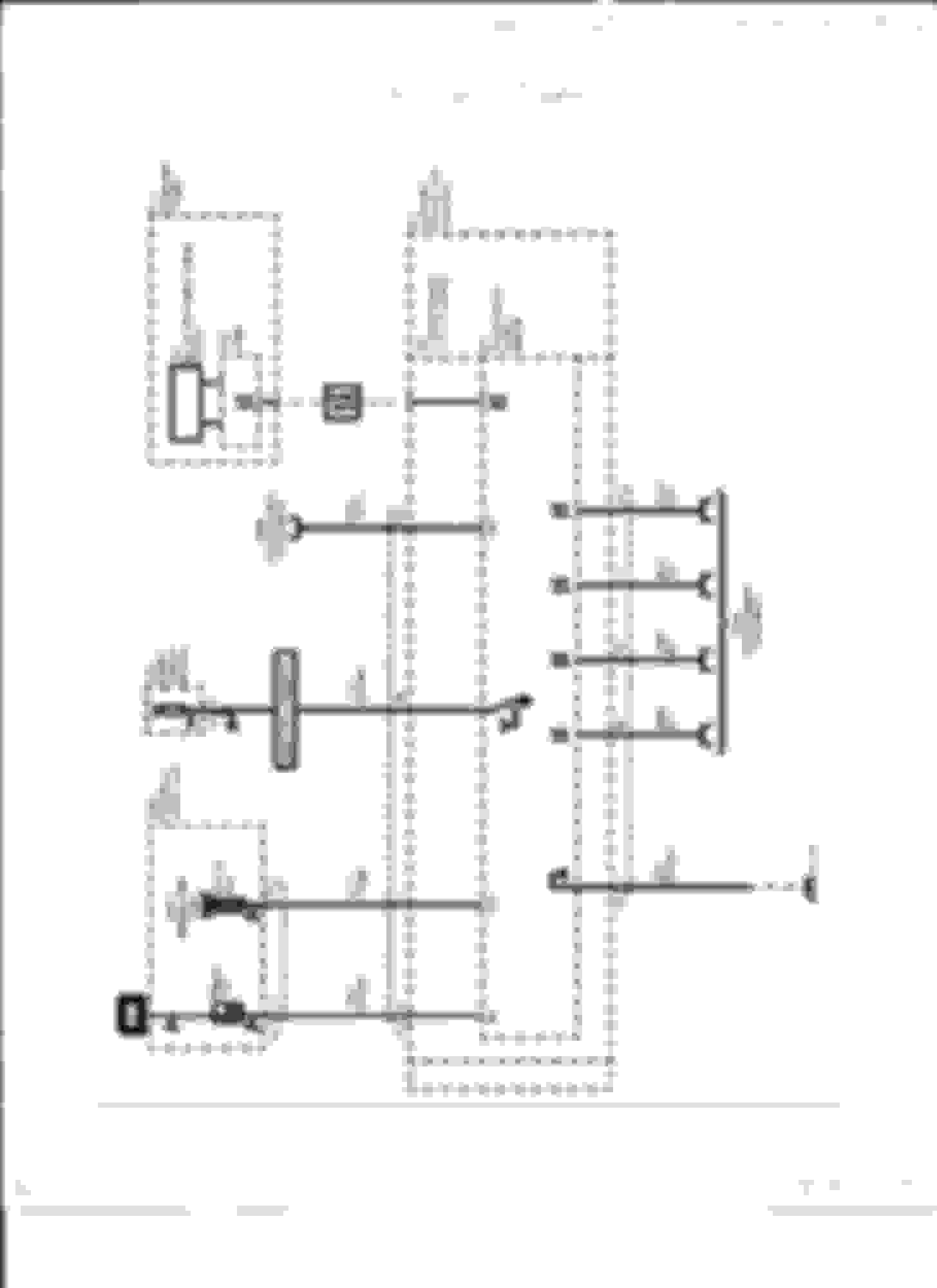
This is what I've found:
Thanks in advance for the help!
Last edited by GENIIIDude; Jan 17, 2016 at 01:53 PM.
Reason: Update
Thanks!! Great info, they match what I'm seeing in my harness. I found the 12v keyed, it was already powered through another circuit that ties to it. The main issue I'm still having is the Brake Signal circuit.
In the first schematic I posted it shows the brake switch signal at pin 6 of the trans plug. This must be a different year/model of application.
On the first schematic you posted it shows pin 6 empty and in my trans plug pin out it is actually empty. Soooo, I have to assume on my application the Brake apply data is sent over the CAN network from the ECM to the TCM?
I dont think you need to worry about those 3 pins and that brake sensor. looks like its there to tell how hard youre pressing the pedal, likely its more for abs and/or traction control.
I dont think you need to worry about those 3 pins and that brake sensor. looks like its there to tell how hard youre pressing the pedal, likely its more for abs and/or traction control.
Good catch - been over those pin outs a million times and missed that! It should have keyed 12v until the brake pedal is pressed then no voltage? Thanks a ton!
Good catch - been over those pin outs a million times and missed that! It should have keyed 12v until the brake pedal is pressed then no voltage? Thanks a ton!
Yep. Get a brake pedal switch from something gym late 80s with cruise control, like Camaro.
Been there myself, eyes start playing tricks after a while staring at wires
That schematic is from LT1Swap.com - These are their words:
"Brake Switch Signal - For automatics with lock up converter, the PCM needs signal when brake pedal is pressed. However, the signal needed is opposite how you're brake lights work. The PCM wants 12v+ constant on this wire when brake IS NOT pressed, and OPEN Circuit when the brake IS pressed. If you vehicle was equipped with a lockup trans to begin with, you probably already have the proper normally closed switch mounted by your brake light switch. If you do not, you can use a relay to perform the same thing. On most relays, there are 5 terminals, 2 of them turn the relay ON when provided ground/power. There are then a normally open leg and a normally closed leg on the relay and a supply. By feeding 12v+ on the supply leg, and hooking the Brake Switch Signal wire to the normally closed leg, you will now have the correct signal for the PCM. When the brake is pressed, 12v+ flows to brake lights, tap into this wire, and run it to the relay to turn the relay on. This will cause the normally closed leg to become open, thus turning OFF the 12v+ signal to the PCM. When you release the brake pedal, the relay will turn OFF, and then feed 12v+ to the PCM."
What I think 12SEC SS is suggesting on some of the 80's G.M. brake light switches on cruise control equipped cars have 4 terminals, it can be wired where 2 of the terminals are NO and the other 2 terminals are NC, so you can use it to de-activate for a the lockup converter, eliminating the need for a relay.
The relay would work, and i was suggesting a GM cruise control switch to replace the one you currently have. I am a firm believer that a part thats not there doesnt break, so my swaps use the gm brake switch with extra terminal.
I had the same problem with my 6L80 install. First I had to get the brake switch wiring correct. I did that but it still did not work with my after market Yank converter. Come to find out the signal to lock up the converter was there but there was not enough pressure applied. So the tuner upped the pressure and all was good.
The relay would work, and i was suggesting a GM cruise control switch to replace the one you currently have. I am a firm believer that a part thats not there doesnt break, so my swaps use the gm brake switch with extra terminal.
I agree, just looking at other options! Thanks for the schematics!
Ok - Tap up / tap down is hooked up, but not working. Here is a screen shot of my HPTuners. Anybody got any idea if I have everything in the tune correct?
Ok - Tap up / tap down is hooked up, but not working. Here is a screen shot of my HPTuners. Anybody got any idea if I have everything in the tune correct?
Start with basics, what are you using for shifter? What os in the pcm? I've plaid some with it before, and for the 1 wire tu/td to work I had to use like a 09 vette os. Log the extra pid's in hptuners scanner, and see if you're registering shifter in S mode. I can look up more info tomorrow if you need.
Start with basics, what are you using for shifter? What os in the pcm? I've plaid some with it before, and for the 1 wire tu/td to work I had to use like a 09 vette os. Log the extra pid's in hptuners scanner, and see if you're registering shifter in S mode. I can look up more info tomorrow if you need.
Shifter is the one from speartech, I believe it is from a G8. The OS is the stock os from a 2014 GMC Sierra 1500.
Gas Monkey Built a 6-Wheel Ferrari Testarossa With a Corvette LT4 Engine
Slideshow: The controversial Ferrari F6 swaps its original flat-12 for a Corvette Z06-derived LT4 V8 and sends power to four rear wheels through a custom-built drivetrain.
7 Most Reliable High-Performance Engines GM Has Ever Built
Slideshow:These GM engines didn't just make huge power, they survived abuse, boost, track days, and six-digit mileage with a reputation for refusing to quit.
6 Common C5 Corvette Failures and What's Involved In Repairing Them
Slideshow: From wobbling harmonic balancers to failed EBCMs, these are the issues that define long-term C5 ownership and what repairs typically involve.
Retro Modern Bandit Pontiac Trans AM Comes With Burt Reynolds' Autograph
Slideshow: A modern Camaro transformed into a retro icon, this limited-run "Bandit" build blends nostalgia with brute force in a way few revivals manage.
Top 10 Greatest Cadillac V Series Performance Models Ever, Ranked
Slideshow: Cadillac didn't just crash the high-performance luxury vehicle party, it showed up loud, supercharged, and occasionally a little unhinged...