When you click on links to various merchants on this site and make a purchase, this can result in this site earning a commission. Affiliate programs and affiliations include, but are not limited to, the eBay Partner Network.
Wiring a 2014 L96 with E38 Harness into a 1972 K20
Hi there! I'm a 16 year old kid looking for a hand on rewiring the engine for my truck. For the past two and a half years I have been learning every part of a restoration from metal fab to paint. I have done EVERYTHING on the truck, besides the powder coated frame. I recently bought a 2014 L96 6.0L from a wrecked Penske Cutaway Van. The engine has 9,000 miles on it and came with the body and engine harness. I am now currently trying to find which wires I need to put power to along with which wires I can either cut off or leave out. I have the E38 computer along with both the engine and body harness. The only things from the body harness that I need are the gas pedal and the data collection tool. If anyone could send me some diagrams or numbers of wiring technicians that I could call for a hand I would seriously appreciate it! The wiring is a big roadblock in the build and the only thing that is preventing it from being driven!
I am now currently trying to find which wires I need to put power to along with which wires I can either cut off or leave out.
I can try to get you started in the right direction. I am am unfamiliar with the exact pinouts of the the truck harness and E38 PCM. However, I have done a lot of work on swapping LS engines using the fbody harness and the 411 pcm, so I assume some of the steps will be the same.
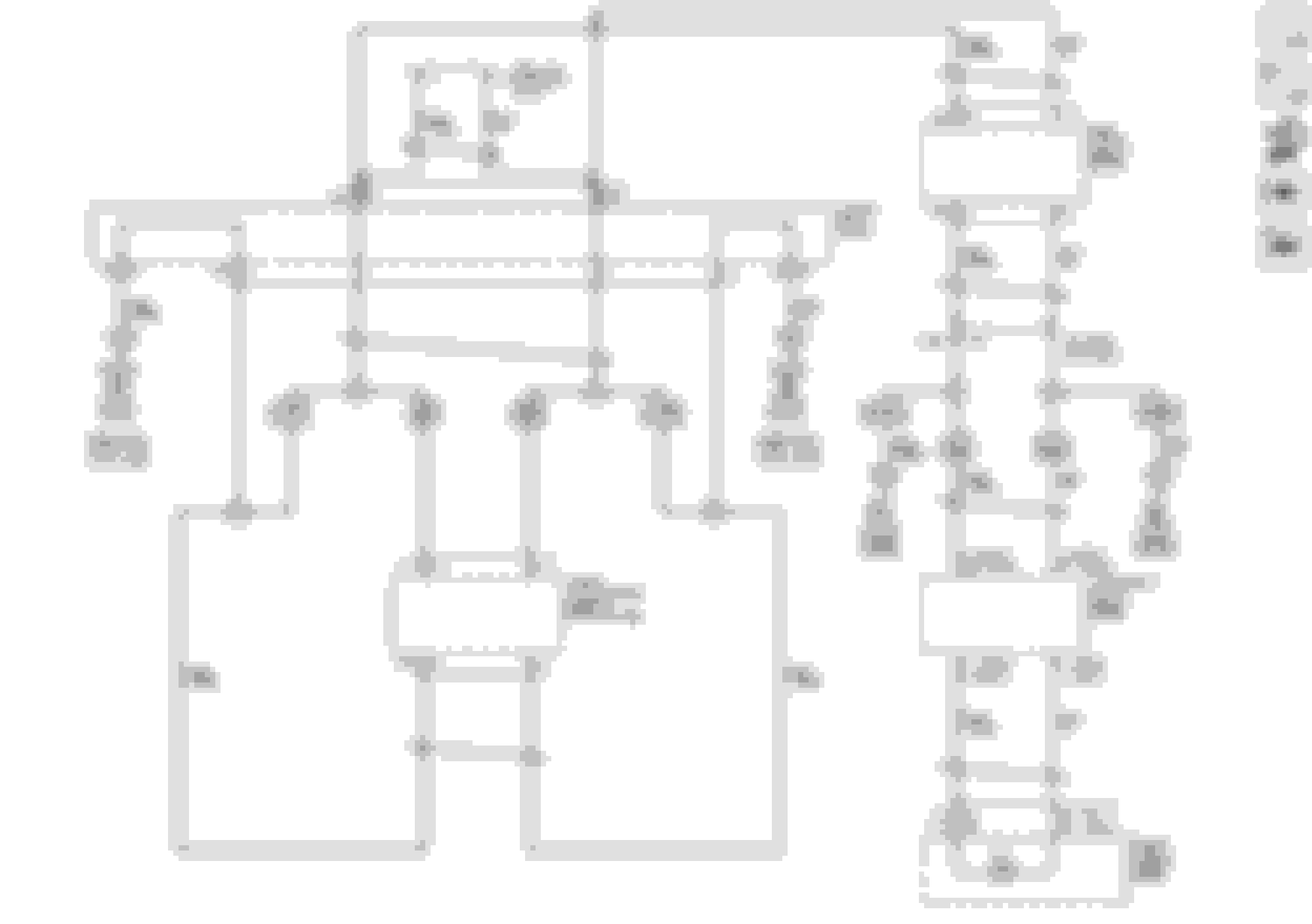
First I would search though the stickies and look for PCM pinout diagrams for your specific PCM. Second, since this is a custom swap, I would unloom the entire engine harness so you can visibly trace each and every wire. I hope you are familiar with using a multimeter to test for continuity as that will help you identify everything.
Start by looking at the primary ignition feeds that you will have to address. On each coil pack harness connector there will be a single pink wire for the ignition feed to power the coils. Trace that wire to it's end and label it. On the fbody harness I believe the ignition wire for each bank of coils is also shared by the injectors on each bank for a single fuse feed per bank. Second, find the mass air flow sensor and the front two oxygen sensor connectors. Each should have a pink wire that feeds ignition power, trace them to their origin and label them. Note, on the Fbody harness these three ignition feeds are connected to each other for a single fuse feed. Third, after looking at the PCM pinout diagram, locate the ignition and direct power feeds for the PCM. On the 411 pcm I believe it is two pink wires for ignition power and one orange wire for direct power. Fourth, there should be an ignition feed for your auto trans. Look for a pinout diagram for your specific transmission. Each of these power feeds will need to be incorporated into the truck fuse block assembly or you'll need to create a separate fuse block assembly for them. Once you have addressed ignition (and direct power, PCM) for the PCM, injectors, coils, MAF, O2's, and transmission, then you should be able to run the engine. I have no experience using the DBW throttle body and pedal, so you'll have to do some research.
I hope that these steps do apply to your specific swap and if they don't, I hope to not add to your confusion.
After that you'll have to address the signal feeds from the engine, transmission, and PCM to get your gauges to function. That's a different can of worms and is specific to your application.
I do not have a PCM because I am putting a NV4500 Transmission with NP Transfer case. The transmission is a 5 speed stick so all I have to worry about is the ECM.
I already got the engine harness down to bare wire so I'll just follow what you gave me from there!
Thank you!
Last edited by pritchardkyler; 02-28-2018 at 03:22 PM.
I do not have a PCM because I am putting a NV4500 Transmission with NP Transfer case. The transmission is a 5 speed stick so all I have to worry about is the ECM.
I already got the engine harness down to bare wire so I'll just follow what you gave me from there!
Thank you!
I use PCM and ECM interchangeably. So when I mentioned PCM, read it as the ECM. Also one thing I forgot to mention was the harness grounds. Power feeds are not worth much without proper grounding. They are usually black wires. Some are easy to spot as they have eyelets crimped on already, others you'll have to tie into a ground manually. Again, having a pinout diagram for your harness will save you a lot of headache.
I use PCM and ECM interchangeably. So when I mentioned PCM, read it as the ECM. Also one thing I forgot to mention was the harness grounds. Power feeds are not worth much without proper grounding. They are usually black wires. Some are easy to spot as they have eyelets crimped on already, others you'll have to tie into a ground manually. Again, having a pinout diagram for your harness will save you a lot of headache.
Ok thank you! I found the pinout so I should be able to route all the wires.
one important thing that is different on the gen iv stuff is the wiring for the can bus. it is basically a loop that runs from the underdash data connector, through all the modules, ecm, bcm, tcm, etc and back. since you're not running some of these modules you will have to make the proper connections that would have been made in the module at the connector for the module...essentially you are just making a jumper wire or just connecting two open ended wires together and just have to make sure that they are connected to the right ones since the coloring of the wires can be similar but different and easy to mix up. i think there is also a terminating resistor that you may have to add but I'd have to take a closer look at things to make sure...its been a while since i did this...hope this helps
btw...that truck is badass and you're doing awesome work especially at your age. wish i had those skills at 16
i'm no expert but have a few swaps under my belt and i think i have some other e38 diagrams that might be helpful so feel free to pm if you need. its always good to post here though so you get different opinions and others can learn from your experience as you go through it so either way
Thank you! That website you shared with me seriously helped out! I printed all of the tables and diagrams out and labeled each wire last night so I could easily finish the harness!


 02-28-2018, 10:41 AM