When you click on links to various merchants on this site and make a purchase, this can result in this site earning a commission. Affiliate programs and affiliations include, but are not limited to, the eBay Partner Network.
Hello. I purchased the one from brand x. But it never worked. Then I purchased one from Amazon. Well it works for a little bit. Then I did my big 3 upgrade and it stopped working. Removed my big 3 and still doesn�t work. I know it says to use a 5v source but I can�t find one in my car. So I used my remote wire from my head it to turn it on and off. What could I use to get a 5v turn on? Thanks
Many sensors use a 5V supply, like most map sensors. Don't use GM cam and crank sensor supplies because they are sometimes 12V and other times 5V.
I just swapped the regulator in my alternator from 4 pin to 2 pin, so now it's like a 2006 or newer alternator. Why??? Because GM thinks it's better than the older 4 pin one and they must know something.
Oh but everyone says you need a late model 2006+ ECM/BCM to run it or it only gives you 13.7 volts. Not necessarily.
Here's the secret why GM puts it in later model cars. The computer can command the alternator to put out any voltage from 11V to 15.5V.
Before the late model engine is started, and also after its shut off, GM can check the condition of your battery. Then they can decide how to charge it and they command the alternator to put out the voltage needed to maintain the battery. Also, the alternator tells the computer if it's having trouble putting out the voltage that the computer commanded. To help the alternator, the computer might raise the idle speed for example.
The L pin is the command voltage pin. A 5V PWM signal is sent from the ECM/BCM at a frequency of 128hz. If the duty cycle is less than 10% or more than 90% or just plain not connected, the alternator will go into default mode and put out about 13.7 volts. Enough to keep your car running, but not enough to charge the battery well. Here are the voltages and duty cycles:
10% = 11.0 V
20% = 11.56 V
30% = 12.12 V
40% = 12.68 V
50% = 13.25 V
60% = 13.81 V
70% = 14.37 V
80% = 14.94 V
90% = 15.5 V
The F terminal is also a PWM signal. But it's put out by the alternator and read by the computer. The lower the duty cycle the easier the alternator is working. If you want to use the alternator and aren't connected to the correct ECM/BCM then you don't need to connect the F terminal.
It remembers the last setting even after it's turned off so once you set it, that's where it will stay. Set the frequency to 128 and then set the duty cycle to whatever voltage you want the alternator to put out. Let's say you're at the track and you want a little more voltage for you fuel pump and coils. Easy. Just raise the duty cycle. Or you left the lights on and your battery is low.... Easy.
Here's how you wire it:
Ignore the Power input -. Apply 5V to the Power input + terminal. You can probably use the 5V signal from the ECM. The PWM controller takes very little power. Connect the ground to signal ground and connect the PWM out to the L terminal of the alternator.
Now go pull that 2 pin alternator out of the trash bin.
7/2021 update. I upgraded my alternator to one of the newer, higher efficiency, higher current, 6 phase hairpin winding designs in anticipation of the higher demands of my new more powerful radiator fan setup and getting my A/C in order. It's controlled by the same 2 pin connector so the PWM generator will work great with these as well. Lots of folks with huge stereo loads are using these alternators for their extra capacity and smoother DC (6 phase) and now they can control them with the PWM generator as well.
What do you mean when you say signal ground? Can I just ground it somewhere?
What do you mean when you say signal ground? Can I just ground it somewhere?
To keep sensors from being affected by devices drawing large currents like fans and fuel pumps, most ECMs use a seperate ground system just for sensors. So for example, a MAP sensor has a 5V supply, an output signal wire and a connection to the signal ground circuit. If you connected the MAP sensor ground to the chassis, the signal to the ECM would have lots of noise on it. So if you're tapping the ECMs 5V supply to provide 5V to the PWM generator, then you may as well tap the signal ground wire to supply a ground to the PWM generator. Using any chassis ground will most likely work in this case as well, since there is no signal back to the ECM, but the 5V supply would then have noise on it going to PWM generator. Much cleaner to use the signal ground circuit.
If you were to provide 5V from some kind of separate supply, like a small buck converter from 12V, then whatever the ground to the separate supply should also be used by the PWM generator.
OK what if I still have the f wire connected? What I did was I cut the L wire and added the PWM in line and used a body ground. I left the f terminal wire connected. I have an LQ4 with the stock pcm and a stand alone harness. It doesn't seem to be working for me.
OK what if I still have the f wire connected? What I did was I cut the L wire and added the PWM in line and used a body ground. I left the f terminal wire connected. I have an LQ4 with the stock pcm and a stand alone harness. It doesn't seem to be working for me.
yeah, that's not right. I don't understand how your stuff is connected. If you already had the L and F wires connected, doesn't that mean that you already had a PCM that supports the 2 pin alternator?? I need to see a diagram of what you had before and after you attached the PWM generator to understand whats going on in your setup. Most people who need this PWM generator don't have anything else attached to their alternator.
yeah, that's not right. I don't understand how your stuff is connected. If you already had the L and F wires connected, doesn't that mean that you already had a PCM that supports the 2 pin alternator?? I need to see a diagram of what you had before and after you attached the PWM generator to understand whats going on in your setup. Most people who need this PWM generator don't have anything else attached to their alternator.
yes I have a pcm that supports a 2 wire alt. Maybe I misunderstood the mod. I want to be able to up my output because i run 3 electric fans and a winch. My truck is always hovering around 13.6v. I thought this would allow me to bump up to 14.5v.
My l wire goes into the v+ from the pcm then out the pmw from the pmw module to the alternator.
yeah, that's not right. I don't understand how your stuff is connected. If you already had the L and F wires connected, doesn't that mean that you already had a PCM that supports the 2 pin alternator?? I need to see a diagram of what you had before and after you attached the PWM generator to understand whats going on in your setup. Most people who need this PWM generator don't have anything else attached to their alternator.
That diagram is definitely not the way to wire it.
If you already have a PWM PCM and you're only at 13.6V then you have other problems. If it's 13.6 at idle and goes up when you at higher RPM then your pulley is too large. If you're always at 13.6, then something is wrong with the PCMs PWM signal or the regulator in the alternator is not right.
If you want a little more juice for the winch, then you can try installing a switch that will switch the L terminal from either your ECM or the PWM module. Then you can run it with the ECM controlling it most of the time and then flip the switch to get a higher voltage when you want to run the winch. But you can't have both of them providing the signal at the same time. You can leave the PWM module on all the time (connected to a real 5V source). Only the wire to the L terminal is switched.
So I'm finally moving away from my carbed n/a setup to the Dominator turbo EFI setup. As such, the alternator control is moving to the dominator.
Is there any advantage to using a 1k ohm resistor and pwm- over the 5.1v zener diode and pwm+, or visa versa? What about a 1W vs 5W 5.1V zener diode if pwm+?
PWM+ with the zener means you don't need to find the 5v supply, otherwise, no benefit. Wattage of the resistor and zener is inconsequential. Currents are around 5ma. Use whichever port you have more spares of.
So I'm finally moving away from my carbed n/a setup to the Dominator turbo EFI setup. As such, the alternator control is moving to the dominator.
Is there any advantage to using a 1k ohm resistor and pwm- over the 5.1v zener diode and pwm+, or visa versa? What about a 1W vs 5W 5.1V zener diode if pwm+?
LOL, I'm quoting myself, but for a good reason. So far this thread is about a fixed voltage from the alternator. But according to the article in the quote, that's not how GM planned to use this alternator.
Obviously, if your setup can support a GM BCM, then that will do what GM intended. Many setups can't run the BCM for many reasons.
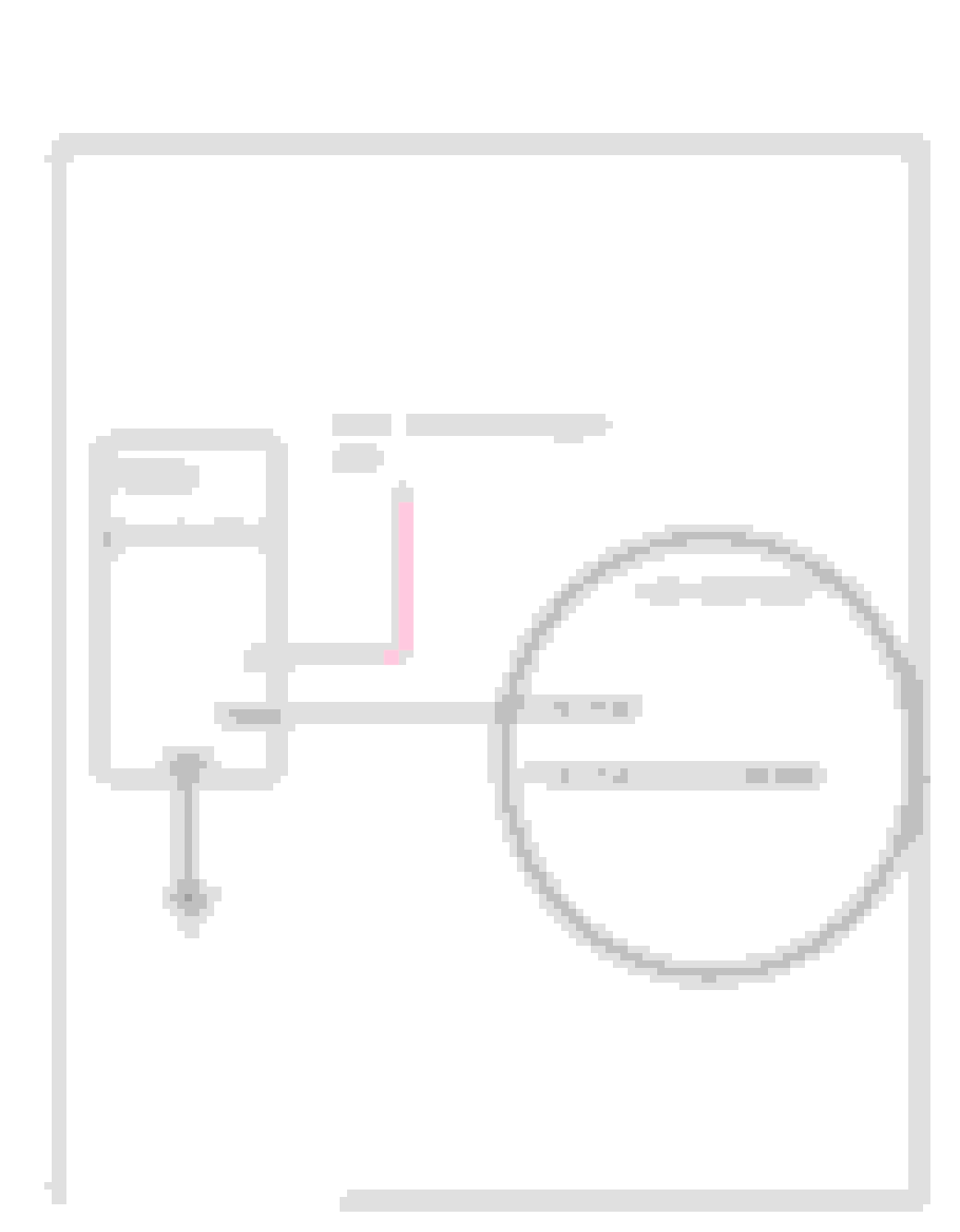
It's not that hard to reproduce a subset of what GM does to manage the battery voltage better with a DIY solution.
Many GM cars that have these alternators also have a battery charge/discharge current sensor. The are readily available and cheap. One of these senors, an arduino nano and two resistors and some code, is probably all you need improve the battery management.
Here's a diagram.
The sensors and most likely the alternators are available on these cars: Part Number: 13505369, 13502261
This item will fit the following vehicles / applications:
2005-2010 Buick Allure
2016 Buick Cascada
2008-2017 Buick Enclave
2013-2016 Buick Encore
2005-2016 Buick Lacrosse
2006-2011 Buick Lucerne
2011-2016 Buick Regal
2005-2007 Buick Terraza
2012-2016 Buick Verano
2013-2016 Cadillac ATS
2008-2016 Cadillac CTS
2006-2011 Cadillac DTS
2007-2015 Cadillac Escalade
2005-2013 Cadillac SRX
2005-2011 Cadillac STS
2013-2016 Cadillac XTS
2007-2013 Chevrolet Avalanche
2010-2015 Chevrolet Camaro
2011-2013 Chevrolet Caprice
2012-2015 Chevrolet Captiva Sport
2005-2010 Chevrolet Cobalt
2014-2016 Chevrolet Corvette
2011-2017 Chevrolet Cruze
2016 Chevrolet Cruze Limited
2007-2009 Chevrolet Equinox
2009-2014 Chevrolet Express 1500
2006-2011 Chevrolet HHR
2006-2016 Chevrolet Impala
2014-2016 Chevrolet Impala Limited
2008-2016 Chevrolet Malibu
2006-2007 Chevrolet Monte Carlo
2012-2014 Chevrolet Orlando
2007-2015 Chevrolet Silverado 1500
2012-2016 Chevrolet Sonic
2016 Chevrolet Spark
2014-2016 Chevrolet Spark EV
2015 Chevrolet Suburban
2007-2014 Chevrolet Suburban 1500
2011 Chevrolet Suburban 2500
2007-2015 Chevrolet Tahoe
2009-2016 Chevrolet Traverse
2013-2016 Chevrolet Trax
2005-2009 Chevrolet Uplander
2007-2016 GMC Acadia
2009-2014 GMC Savana 1500
2007-2015 GMC Sierra 1500
2007-2015 GMC Yukon
2015 GMC Yukon XL
2007-2014 GMC Yukon XL 1500
2008-2009 Hummer H2
2007-2010 Pontiac G5
2008-2010 Pontiac G6
2005-2008 Pontiac Grand Prix
2005-2009 Pontiac Montana
2005-2006 Pontiac Pursuit
2007-2009 Pontiac Torrent
2007-2009 Saturn Aura
2007-2010 Saturn Outlook
2005-2007 Saturn Relay
2008-2010 Saturn Vue
A truly OUTSTAND posting of information and knowledge.
Thank you Everyone!
But this does bring up a question. I will be using a two wire DR44 alternator with one of the PWM controllers (not sure which one I should use without an ECM) and understand the workings by adjusting the % to change the output voltages. It sounds like it is a set consistent output voltage (as stated in the above posting). Set to 14.5 VDC always charging 14.5 VDC. Is this correct?
The purpose of the stock voltage regulator (going back to the 50's) is to monitor the electrical requirements and battery state of charge to adjust its output so that it does not over or under charge the battery. Running a set voltage cannot be a good thing in the long run for the battery.
I understand the above post. I can buy the Nano and the required parts, but the "some code" is where my abilities come to a stop.
In the RV/camper and solar charging worlds, they use a DC to DC controller/converter to control the charging rate and battery state.
It sounds like it is a set consistent output voltage (as stated in the above posting). Set to 14.5 VDC always charging 14.5 VDC. Is this correct?
Batteries have been charged with constant voltage far longer than they have with advanced logic. Not as good for the batteries, but acceptable for sure. Not sure the optimum voltage for constant charge, but mine are set to 14.1 for now.
Originally Posted by Larry-Cleveland
I understand the above post. I can buy the Nano and the required parts, but the "some code" is where my abilities come to a stop.
At some time in the future, I'll probably write some code to emulate a subset of the modern GM charging algorithms with the diagram above. Just a minimum set would not be difficult.
For example:
if charge current trickles off, then lower the voltage.
Don't turn on charging and measure the voltage. Then use a table to estimate how long you need to blast the battery with high charging rate before returning to normal.
I'm Busy now so not working on this right away.
Originally Posted by Larry-Cleveland
In the RV/camper and solar charging worlds, they use a DC to DC controller/converter to control the charging rate and battery state.
Would something like this work for us?
Sure, that would work. I don't have much experience there, but that's a big market with lots of vendors, and I bet many charge controllers have advanced logic to optimize the battery type.
@LSswap , thanks for your great contribution for this thread. I am currently in need of an alternator for my LS swap. I can fit the CS130 105 amp unit but I need more amps. I tried to fit the 140 amp LS larger case but it doesn't fit, the case diameter is too large:
The Powermaster 48206 seems like it could fulfill my needs but I am very intrigued by the newer design alternators, especially the 6 phase, 'hairpin' design. Are those the LT alternators shown here?:
Or maybe the 2019+ version shown here (assuming bolt spacing is still 5.46). (Looks like it might even be smaller than the LT versions shown above). https://www.ebay.com/p/22037449882
I can see that these have the same bolt spacing and would likely work with my ICT billet mounting bracket but what I can't seem to find out is the dimensions of the cases.
QUESTIONS:
1) What are the alternators with the 6 phase hairpin design?
2) what alternator(s) have a 140+ amp output with the same or smaller case diameter to the 105 amp LS alternator? (Even if they are not the hairpin design)
3) are these alternators able to be clocked if need be for clearance?
4) I will be running a Holley Terminator X but if I wanted to avoid tying up an output for my alternator would there be any reason to not run a PWM generator?
5) any particular PWM generator that is recommended (or should be avoided)?
6) Any reason that it would be bad to just set the alternator to ~14.6 V permanently instead of controlling it like the factory ECU does?
Thank you in advance
Last edited by fusion_ta66; 11-10-2023 at 12:40 AM.
1) What are the alternators with the 6 phase hairpin design? Hairpin design allows more dense winding in a smaller space, so they can be more efficient. 6 phase provides a DC output with less ripple (noise). 6 Phase have double the number of diodes, so more current potential. I think they are a better choice.
2) what alternator(s) have a 140+ amp output with the same or smaller case diameter to the 105 amp LS alternator? (Even if they are not the hairpin design) I don't know, maybe someone else can chime in.
3) are these alternators able to be clocked if need be for clearance? I can't see why they can't be clocked.
4) I will be running a Holley Terminator X but if I wanted to avoid tying up an output for my alternator would there be any reason to not run a PWM generator? Only benefit with Holley is less parts, unless you want to set up some elaborate tables that change the voltage. PWM generator is proven.
5) any particular PWM generator that is recommended (or should be avoided)? I don't like the ones that run of 12V because they could trash the regulator if they are not set up right to only put out a 5V pulse. Much safer to run a PWM generator without that feature and power it from 5V.
6) Any reason that it would be bad to just set the alternator to ~14.6 V permanently instead of controlling it like the factory ECU does? I know some older alternators run at a higher voltage for decades, so it can't be too bad to run a constant voltage. I don't know what the ideal voltage is. I run 14.1 but it's prob a bit low.
Thanks @LSswap . Do you know specifically which alternators have the 6 phase hairpin design? For example, do all the Gen V alternators have it, or only after a certain year?
Do you have a specific model of PWM generator that you run or recommend?
6) Any reason that it would be bad to just set the alternator to ~14.6 V permanently instead of controlling it like the factory ECU does?
A flat voltage is still widely used with large diesel engines in construction and mining equipment. It is not ideal but you'll still get around 5 years of life out of the battery. Anywhere between 13.5 - 14.5V would be acceptable but somewhere closer to the middle 13.75 - 14.0V would be preferred.
Try to stay away from the high side (14.5V) if mostly driving in hot weather because battery will be constantly overcharged and reduce battery operating life. And that would be even more detrimental to AGM type batteries. If you have no other choice, then choose a flooded lead acid battery with fill caps so you can replenish water now and then.
The "ideal" charging voltage is based on what is good for battery health, and that changes depending on battery temperature and state of charge. Modern cars have temperature, voltage, and current sensors to gather data about the battery and then apply algorithms (charging model) to decide what voltage to apply to battery. The OEM's were able to increase battery life dramatically by paying attention to these details.

 05-18-2023, 02:32 PM


 sQAAOSwMudblh4p:rk:13:pf:0