When you click on links to various merchants on this site and make a purchase, this can result in this site earning a commission. Affiliate programs and affiliations include, but are not limited to, the eBay Partner Network.
For those looking for a 5v power source I tapped into the 5v reference from the EGR plug which is conveniently located by my relocated alternator on my 2000 camaro. Set @ 70% DC, voltage is higher and more consistent than it ever has been with a ~160k mile alternator that's been sitting in a crate for years.
-Beau
Thanks for the info, I built the design as a standalone controller for my bracket racer S10 with a carb, excellent tech and it works perfectly.
Now I just need a similar design to trigger LS coils on in order to bench test them, I'm not sure what is needed to trigger the coils, is it just voltage or another command scenario?
thanks mike
Glad the alternator worked out for you.
Well coils are a little off topic, but.... all you need for LS coils is a low power 5V on the signal wire for a short time to charge the coils and bring that signal to ground to fire the coils. Make sure you don't turn them on for more than 4 milliseconds (I'm guessing here) or you may fry the coils. Maybe try on time of 3 milliseconds for testing. An arduino nano can be used to test them better than one of the PWM generators, less chance of keeping the pulse on too long. So 3 milliseconds on and 500 milliseconds off should give you about 2 sparks per second. Be careful. Make sure the sparks have a path to a good ground.
I�ve read through this thread and maybe someone can help with my setup. I�ve dropped an 09� 4.8 engine into my 72� C20. The alternator is stock and connected to the ECM in the stock location. I�ve got the battery sensor on the negative cable, but no body control module. Is it possible to use the sensor to communicate with the alternator through the ECM? I also picked up a PWM generator after reading this thread, but if I don�t need it, could skip it. The engine is running and shows 13.8V in HP Tuners, which leads me to believe it�s running in default mode. Thanks!
I�ve read through this thread and maybe someone can help with my setup. I�ve dropped an 09� 4.8 engine into my 72� C20. The alternator is stock and connected to the ECM in the stock location. I�ve got the battery sensor on the negative cable, but no body control module. Is it possible to use the sensor to communicate with the alternator through the ECM? I also picked up a PWM generator after reading this thread, but if I don�t need it, could skip it. The engine is running and shows 13.8V in HP Tuners, which leads me to believe it�s running in default mode. Thanks!
Tried hooking up the PWM generator to the alternator and no luck getting it to work at anything other than 13.8V. The generator was set to output 5V (input on my unit was from pink, key hot 12V),128Hz, and the output varied between 40 - 100%. We got varied voltage output readings with a multimeter so it seems to be working properly. But the alternator was reading 13.8V in the HP Tuners scanner regardless of settings. Battery multimeter readings were slightly lower around 13.5V. Even more odd was when the alternator signal connector was taken off, there was no change either - still showing 13.8 on the scanner� Not sure what to try next. The PWM signal was supplied to the Generator Field Duty Cycle Signal wire which was pulled from the X2 connector.
The PWM signal was supplied to the Generator Field Duty Cycle Signal wire which was pulled from the X2 connector.
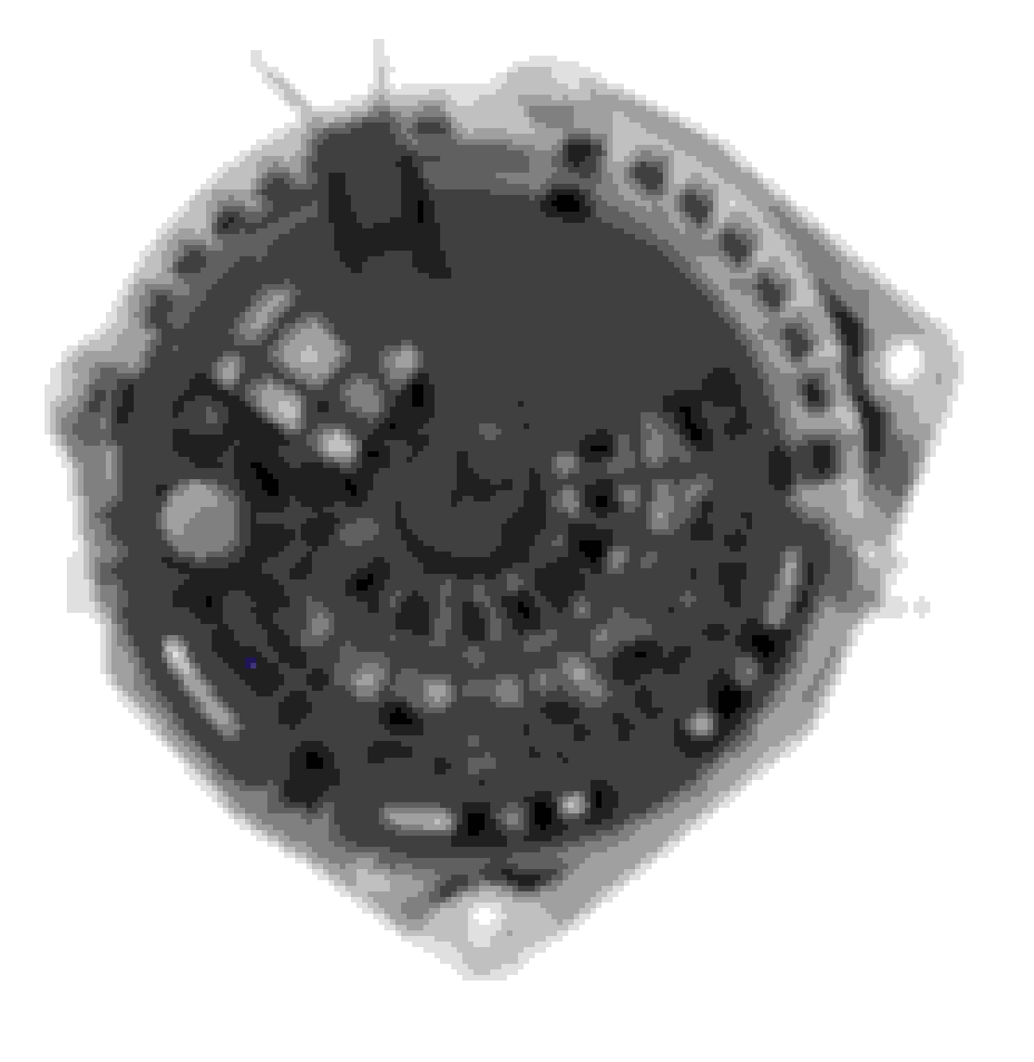
That's the wrong pin. The Generator Field Duty Cycle Signal wire is the "F' pin not the "L" pin. Look at the picture of the alternator where I marked the "F" and the "L" pin. The F pin is status PWM generated by the alternator to tell the ECM how the alternator is doing. if there is no ECM, leave the "F" pin not connected. The 5V PWM signal that controls the alternator only goes to the "L" pin.
If you are using the PWM generator, make sure you don't have the "L" pin also connected to the BCM or ECM.
I am using the ECM - what I can't figure out is whether the ECM can drive the variable output or whether it requires the battery current sensor to provide that feedback?
I found some extra display parameters in HP Tuners scanner which show the F & L pin and one varied in % while the other stayed at 99%. It's not in front of me, but maybe it already works as it should?
I just swapped the regulator in my alternator from 4 pin to 2 pin, so now it's like a 2006 or newer alternator. Why??? Because GM thinks it's better than the older 4 pin one and they must know something.
Oh but everyone says you need a late model 2006+ ECM/BCM to run it or it only gives you 13.7 volts. Not necessarily.
Here's the secret why GM puts it in later model cars. The computer can command the alternator to put out any voltage from 11V to 15.5V.
Before the late model engine is started, and also after its shut off, GM can check the condition of your battery. Then they can decide how to charge it and they command the alternator to put out the voltage needed to maintain the battery. Also, the alternator tells the computer if it's having trouble putting out the voltage that the computer commanded. To help the alternator, the computer might raise the idle speed for example.
The L pin is the command voltage pin. A 5V PWM signal is sent from the ECM/BCM at a frequency of 128hz. If the duty cycle is less than 10% or more than 90% or just plain not connected, the alternator will go into default mode and put out about 13.7 volts. Enough to keep your car running, but not enough to charge the battery well. Here are the voltages and duty cycles:
10% = 11.0 V
20% = 11.56 V
30% = 12.12 V
40% = 12.68 V
50% = 13.25 V
60% = 13.81 V
70% = 14.37 V
80% = 14.94 V
90% = 15.5 V
The F terminal is also a PWM signal. But it's put out by the alternator and read by the computer. The lower the duty cycle the easier the alternator is working. If you want to use the alternator and aren't connected to the correct ECM/BCM then you don't need to connect the F terminal.
It remembers the last setting even after it's turned off so once you set it, that's where it will stay. Set the frequency to 128 and then set the duty cycle to whatever voltage you want the alternator to put out. Let's say you're at the track and you want a little more voltage for you fuel pump and coils. Easy. Just raise the duty cycle. Or you left the lights on and your battery is low.... Easy.
Here's how you wire it:
Ignore the Power input -. Apply 5V to the Power input + terminal. You can probably use the 5V signal from the ECM. The PWM controller takes very little power. Connect the ground to signal ground and connect the PWM out to the L terminal of the alternator.
Now go pull that 2 pin alternator out of the trash bin.
7/2021 update. I upgraded my alternator to one of the newer, higher efficiency, higher current, 6 phase hairpin winding designs in anticipation of the higher demands of my new more powerful radiator fan setup and getting my A/C in order. It's controlled by the same 2 pin connector so the PWM generator will work great with these as well. Lots of folks with huge stereo loads are using these alternators for their extra capacity and smoother DC (6 phase) and now they can control them with the PWM generator as well.
so I tried this. I have the PWM generator sending 128hz to my L pin on my alternator. Out of the alternator I am reading nothing (just battery voltage, around 12.2v as the battery is a little low). I made sure I�m getting 5vdc to the PWM generator +, connected the ground wire on the generator to battery ground, and I�m getting 128hz to the L pin on the alternator (measured with an o-scope). I unplug the connector cause I assume I will get 13vdc + with no input and nothing (still battery voltage) coming out of the output post on the alternator. I replaced the alternator with another one (same brand, Remy 91615 alternator). Belt is tight, spins alternator fine. Anyone have any suggestions? Thanks!
I just swapped the regulator in my alternator from 4 pin to 2 pin, so now it's like a 2006 or newer alternator. Why??? Because GM thinks it's better than the older 4 pin one and they must know something.
Oh but everyone says you need a late model 2006+ ECM/BCM to run it or it only gives you 13.7 volts. Not necessarily.
Here's the secret why GM puts it in later model cars. The computer can command the alternator to put out any voltage from 11V to 15.5V.
Before the late model engine is started, and also after its shut off, GM can check the condition of your battery. Then they can decide how to charge it and they command the alternator to put out the voltage needed to maintain the battery. Also, the alternator tells the computer if it's having trouble putting out the voltage that the computer commanded. To help the alternator, the computer might raise the idle speed for example.
The L pin is the command voltage pin. A 5V PWM signal is sent from the ECM/BCM at a frequency of 128hz. If the duty cycle is less than 10% or more than 90% or just plain not connected, the alternator will go into default mode and put out about 13.7 volts. Enough to keep your car running, but not enough to charge the battery well. Here are the voltages and duty cycles:
10% = 11.0 V
20% = 11.56 V
30% = 12.12 V
40% = 12.68 V
50% = 13.25 V
60% = 13.81 V
70% = 14.37 V
80% = 14.94 V
90% = 15.5 V
The F terminal is also a PWM signal. But it's put out by the alternator and read by the computer. The lower the duty cycle the easier the alternator is working. If you want to use the alternator and aren't connected to the correct ECM/BCM then you don't need to connect the F terminal.
It remembers the last setting even after it's turned off so once you set it, that's where it will stay. Set the frequency to 128 and then set the duty cycle to whatever voltage you want the alternator to put out. Let's say you're at the track and you want a little more voltage for you fuel pump and coils. Easy. Just raise the duty cycle. Or you left the lights on and your battery is low.... Easy.
Here's how you wire it:
Ignore the Power input -. Apply 5V to the Power input + terminal. You can probably use the 5V signal from the ECM. The PWM controller takes very little power. Connect the ground to signal ground and connect the PWM out to the L terminal of the alternator.
Now go pull that 2 pin alternator out of the trash bin.
7/2021 update. I upgraded my alternator to one of the newer, higher efficiency, higher current, 6 phase hairpin winding designs in anticipation of the higher demands of my new more powerful radiator fan setup and getting my A/C in order. It's controlled by the same 2 pin connector so the PWM generator will work great with these as well. Lots of folks with huge stereo loads are using these alternators for their extra capacity and smoother DC (6 phase) and now they can control them with the PWM generator as well.
Will this setup work for 2 Pin alternator on a 2007 Cadillac escalade esv? I'm running a dual battery setup with two identical agm batteries with a isolator but my issue is cause of the current sensor not putting out enough voltage for the two agm batteries so I came across tbis post cause I was trying to find away t OK bypass the current sensor and put out 14.5 to 14.8 Constantly. I run a 1,500 high power amp in the back that's rated for 14.5 volts too with subs and I have a lot of external lighting I run too alternator charges the second battery but not good enough and alway low when I check em but enough to start vehicle still, I also upgraded all my battery cables to a copper 2 guage. So I'm curious as if this will work good for my setup and be I. Control of voltage?
Here is how I would try it connecting to PWM-. Please keep in mind that I can't test this.
The L pin is the command voltage pin. A 5V PWM signal would be sent from the Holley at a frequency of 128hz. Here are the PWM duty cycles I would try for PWM-. They are the opposite of PWM +.
90% = 11.0 V
80% = 11.56 V
70% = 12.12 V
60% = 12.68 V
50% = 13.25 V
40% = 13.81 V
30% = 14.37 V
20% = 14.94 V
10% = 15.5 V
I now have this working using 5V from the TPS sensor wire (unused, FBW), 1K Ohm pullup, and PWM- coming of J1 connector from Holley. Works exactly as theorized above. 30% duty cycle commanded 14.3V. Now I plan to wire it in more cleanly and see if I can somehow read the alt PWM output into the Terminator for variable alt control.
Is there any info regarding alternator case size with the two wire connection? I want to be able to use the controller from this thread.
I have a DR37 and DR44 case alternator with the DR37 being smaller diameter.
The problem I have is with a custom alternator mount, the driver side turbo header is touching as it goes over top.
Do cars have physically smaller cases with same mounts as the trucks?
This is a bracket race S10.
Supplying 12volt to regulator instead of 5volt will kill the regulator!
Also if you try to increase duty cycle say with boost like go from 71% to 73% in mid boost the PID control on regulator will go funky and can lead to massive oscillations like jump past 16volts
Set your duty static, in my case i have battleborn 100amp battery that will make your alternator cry, so i set 13.9 volt for first 5 min (Estimating average change time) of engine running then bump it to 14.8 volt after.
I got my standalone to work with the regulator using the 5v zener diod and resistor!
I now have this working using 5V from the TPS sensor wire (unused, FBW), 1K Ohm pullup, and PWM- coming of J1 connector from Holley. Works exactly as theorized above. 30% duty cycle commanded 14.3V. Now I plan to wire it in more cleanly and see if I can somehow read the alt PWM output into the Terminator for variable alt control.
Thanks!
Are you happy to go into a bit more detail about what you've put together here? Sounds like your objective is to have a neat result and I'd like to achieve the same, but I'm straying into an area I'm not familiar.
I'm using the Terminator X and looking to use Pin H (see Connector J1 A/B input/Output Auxillary Harness) as the source for the PWM-.
Thanks
Rick
Hey Rick, I can't recall off the top of my head which J1 output I used, but there are 4 outputs you can choose from:
I'm using 1 of the PWM (P-) outputs for my SPAL brushless fan control, and the other for the ALT. Since you just set this up in software, it doesn't really matter which of the 4 J1 output pins you choose, just be sure you know how to map it back the right pin in your tune.
From there, you simply have to wire in a 5V pull-up. The way I did that was to to tie into one of my unused sensor wires, in my case I just grabbed TPS sensor that is not used in my Drive by Wire setup, and then connect a 1kOhm resistor to the PWM wire coming from J1 going to the ALT.
*****EDITED**** Corrections made and incorrect link removed to avoid future confusion.
Hey Rick, I can't recall off the top of my head which J1 output I used, but there are 8 outputs you can choose from:
https://documents.holley.com/199r12232.pdf (page 2)
Output Types Each output channel on the module can be configured as one of the following types: Switched-low (“G”) Switched-low PWM (“P-“)
This document also describes how to set up the output in the Holley SW.
I'm using 1 of the PWM (P-) outputs for my SPAL brushless fan control, and the other for the ALT. Since you just set this up in software, it doesn't really matter which of the 8 J1 output pins you choose, just be sure you know how to map it back the right pin in your tune.
From there, you simply have to wire in a 5V pull-up. The way I did that was to to tie into one of my unused sensor wires, in my case I just grabbed TPS sensor that is not used in my Drive by Wire setup, and then connect a 1kOhm resistor to the PWM wire coming from J1 going to the ALT.
A big thank you for responding to my question.
Thanks for the link to the Holley doc. I hadn't seen this one, but super useful.
I'm comfortable with getting the right output from the ECU. Based on the info in Connector J1 A/B input/Output Auxillary Harness, the Terminator X only supports output on pins E, F, G & H (on the "INPUT/OUTPUT" connector). I was planning on just using the factory setting for the twin radiator fans, which are pins E & F. This is because these pins support 12V switched outputs, so can be used to control the relays for the fans. These two pins also support PWM+, but they're already busy controlling the fans. Pins G and H support PWM- (or can be used as switched ground outputs), hence why I picked Pin H.
It's what happens between leaving the ECU and the signal arriving at the alternator that has me puzzled. I think I understand what we are trying to do. It is the how that I still need to work out (with a view to then wiring everything correctly).
If I understand right, the Holley ECU will put out a PWM+ signal at 12V (up to 2AMPS, based on the doc you shared). 12V would quickly fry the alternator. Out of the factory the alternator will receive 5V. So we want a 5V signal at the alternator. Hence the solution at post #7.
However, I'm using PWM-, same as you. You're using the 5V from the TPS as a 5V source. Combine that 5V power source with the pull-up resistor and splice the ground PWM signal, and the output is5V PWM+. (Is that correct?) The duty cycles are no longer reversed. How that works is beyond my current understanding of electronics, but a bit off googling is filling in some blanks. Google has also shown that I'm not the only one trying to understand the science here.
Thanks again for your help (and all the other contributors to this thread, in particular the OP).
Disregard the link I posted above - I got in a hurry while on a conference call and now realize that is for a CAN Input/Output Module add on for Holley ECUs.
However, For Terminator X, all 4 outputs are G or P-, P+ is NOT supported by Terminator X. I searched and can't find the documentation for that, because I think they reused and didn't update the Dominator and other ECU documents that show they support P+ on two of the pins. You'll find, like I did, PMW+ is not an option anywhere in the SW.
"However, I'm using PWM-, same as you. You're using the 5V from the TPS as a 5V source. Combine that 5V power source with the pull-up resistor and splice the ground PWM signal, and the output is5V PWM+. (Is that correct?) The duty cycles are no longer reversed. How that works is beyond my current understanding of electronics, but a bit off googling is filling in some blanks. Google has also shown that I'm not the only one trying to understand the science here."
You are exactly right here. With PWM- the ECU modulates ground to the the wire, so the ALT needs to be normally high (+5V) and pulled down for the on duty cycle. That's why you have to use reverse logic for the PWM control -> lower PWM % commands higher fan speed.
However, For Terminator X, all 4 outputs are G or P-, P+ is NOT supported by Terminator X. I searched and can't find the documentation for that, because I think they reused and didn't update the Dominator and other ECU documents that show they support P+ on two of the pins. You'll find, like I did, PMW+ is not an option anywhere in the SW.
"However, I'm using PWM-, same as you. You're using the 5V from the TPS as a 5V source. Combine that 5V power source with the pull-up resistor and splice the ground PWM signal, and the output is5V PWM+. (Is that correct?) The duty cycles are no longer reversed. How that works is beyond my current understanding of electronics, but a bit off googling is filling in some blanks. Google has also shown that I'm not the only one trying to understand the science here.".
Post number 51 details both PWM- and PWM+ configurations.


 10-03-2021, 12:06 PM


 sQAAOSwMudblh4p:rk:13:pf:0