When you click on links to various merchants on this site and make a purchase, this can result in this site earning a commission. Affiliate programs and affiliations include, but are not limited to, the eBay Partner Network.
Curious, what plug wires are those, Taylor? Liking your build, very detailed.
Thanks, the plug wires came with my speed engineering headers. I'm not sure of the brand other than that, but they seem to fit fairly well. They had 2 options for plug wires - a short length and a long length. These were the shorter ones and I'm glad I went with them instead of the long ones. They could actually be about an inch or 2 shorter and still be plenty long enough!
After we got the engine and trans installed, there wasn't much time to get a whole lot else done since we had to clean up the massive mess that had become my garage. Over the last few days though I did have some time to get out to the garage and do some more installing / test fitting of other components. First, I wanted to tackle my cold air intake as I wasn't sure I was going to be able to make my 90 degree elbow and 45 degree tube work with the S&B filter I purchased. A quick test fit showed that I will have about 3/4" (or about 20mm) of clearance between the clean side tube and the tensioner pulley.
This amount of clearance actually worked out perfectly for the amount of drop I wanted in the tube, and placed the filter quite nicely in the old battery tray location. I cut up some cardboard and transferred the profile/contours of the inner fender well to it so I had a tight fitting profile between that and what would be my air box template. It extends from the core support rearward to an approximately 45degree bend outboard, then it extends out to the fender. I traced this bent shape onto another piece of cardboard to form a lid template. Then I used my utility knife to cut out an inspection window. I still need to trim the 45degree tube on one end to allow the filter to be installed higher on the tube and more in line with the inspection window. Parts used for the cold air intake: S&B Filter CR-40035D; Summit Racing 4" aluminum tube SUM-294544; Spectre 90 degree elbow with convolutes SPE-9785.
Next, I needed a belt for my AC compressor. After doing some research, I found a YouTube video of a guy doing an install on his TBSS where he converted from the tensioner style to the stretch belt style that GM went to. Long story short, he ended up going with a belt about 1.125" shorter than the tensioner style belt. He looked up the compressor pulley size and crank pulley size for a 5th gen Camaro SS and found they were identical to his TBSS and the center to center distance was the same as well, so he looked up the difference in length between the stretch belt and the tensioner belt to come up with the ~1.125" delta. Holley says I need a 37.75" long belt, so doing the math I came up with a 36.625" belt length. Gates K4040360 measures out to 36.625" so I purchased that and installed it (using no special tools).
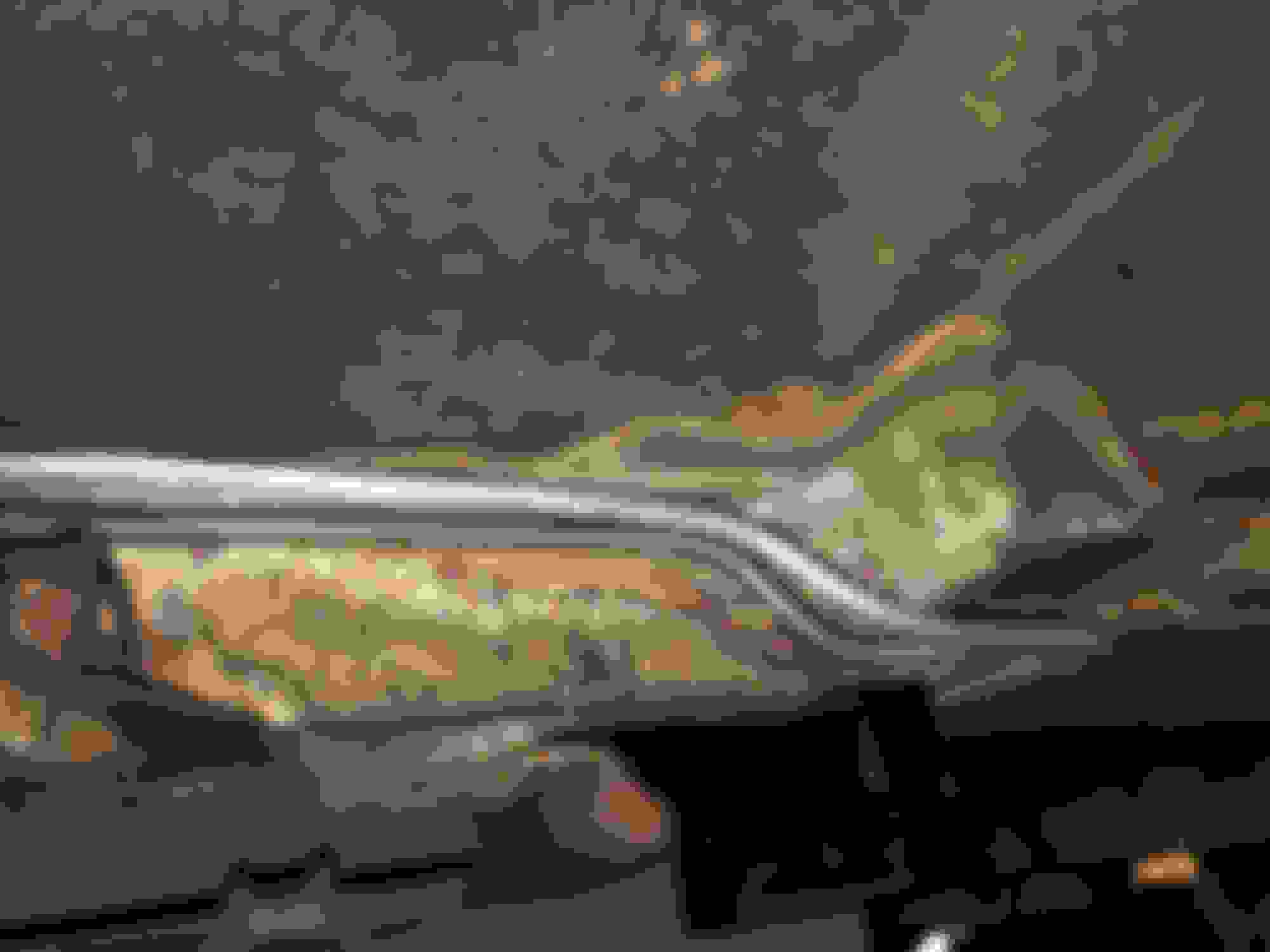
Moving on to the power steering system, I needed new hoses, so I just purchased stock replacement pieces. The replacement pump I bought for the LS used the new style bubble flare or o-ring fitting whatever you want to call it, it was different than my 78 Nova hose end. Thanks to GM, I was able to transfer the old fitting from the back of my original SBC pump to the new LS pump and the replacement pressure hose bolted right up.
It's hard to get a good picture of how far down the pressure hose hangs, but it's actually just above the pitman arm and far enough away that it wouldn't ever touch even at full lock.
Lots of clearance between the PS pulley and the steering gear box / hoses. Also, belt changes will be a non-issue as I have had this serpentine belt on/off several times so far since it has been in the car.
Next I started working on the AC hose and heater hose routing. I knew I wanted to run the hoses through the fender to hide them as much as possible. I will end up using a 45 degree fitting on both the #8 and #10 hoses coming out of the compressor and then have the service ports right behind the airbox. I tweaked the angles of the heater hose fittings to get a tighter grouping on my hose bundle and tidy it up a bit. There should be plenty of slack in this hose bundle for engine roll as I am not hard mounting them to anything on the chassis. I will probably zip tie them together or try and find some kind of clamp that can hold them in a bundle.
Small update - Got my new electronic speedometer installed in my gauge cluster to replace my old mechanical one. I have also started re-doing the wiring under the dash for several things to try and tidy it up a bit. It's impressive how much stuff gets tacked on over the years. I'll also be adding a check engine light to the dash so I can wire that up and know if/when it throws the CEL/MIL.
I finished routing my AC / heater hoses and got everything cut to length. All connections at the firewall will be with a 90 degree fitting to route them all through the fender and clean up the engine bay. Even in Metro Detroit, I am not having any luck finding someone to crimp my AC lines locally and the place back home that did it 10+ years ago is no longer crimping hoses/fittings they did not sell. I put a call in to Vintage Air because I have heard that they will either rent the crimping tool to you or crimp your lines if you pay shipping. I chose the latter after talking with the rep and the hoses were sent out today UPS. You will also see my starter cable that I have routed behind the starter and up the firewall in anticipation of placing my main battery power distribution block. I need to figure out where I'm going to be drilling the hole in my trunk floor for the positive cable to route through, as I will be running it along the same routing that the factory carbureted fuel line ran. I will be moving the fuel supply line to the driver side of the car to better meet up with where the port is on the fuel rail and to prevent having fuel and battery positive cable run right next to one another.
I put a call in to Vintage Air because I have heard that they will either rent the crimping tool to you or crimp your lines if you pay shipping. I chose the latter after talking with the rep and the hoses were sent out today UPS.
Did you confirm that they rent the tool? If so, why did you choose to send your hoses to them instead of renting the tool? Was it less expensive to go that route?
thanks, I�m getting anxious too for getting it started up. Still waiting on my fuel tank from Tanks, but they say it should be going out this week or next.
Originally Posted by rmchevelle
Did you confirm that they rent the tool? If so, why did you choose to send your hoses to them instead of renting the tool? Was it less expensive to go that route?
It will probably depend on where you are shipping from and how many hoses you need crimped, but they are really easy to talk to for discussing the options. For me, shipping the hoses to them was the better option. Probably best to contact Vintage air directly though to discuss availability and pricing rather than on the forum.
It will probably depend on where you are shipping from and how many hoses you need crimped, but they are really easy to talk to for discussing the options. For me, shipping the hoses to them was the better option. Probably best to contact Vintage air directly though to discuss availability and pricing rather than on the forum.
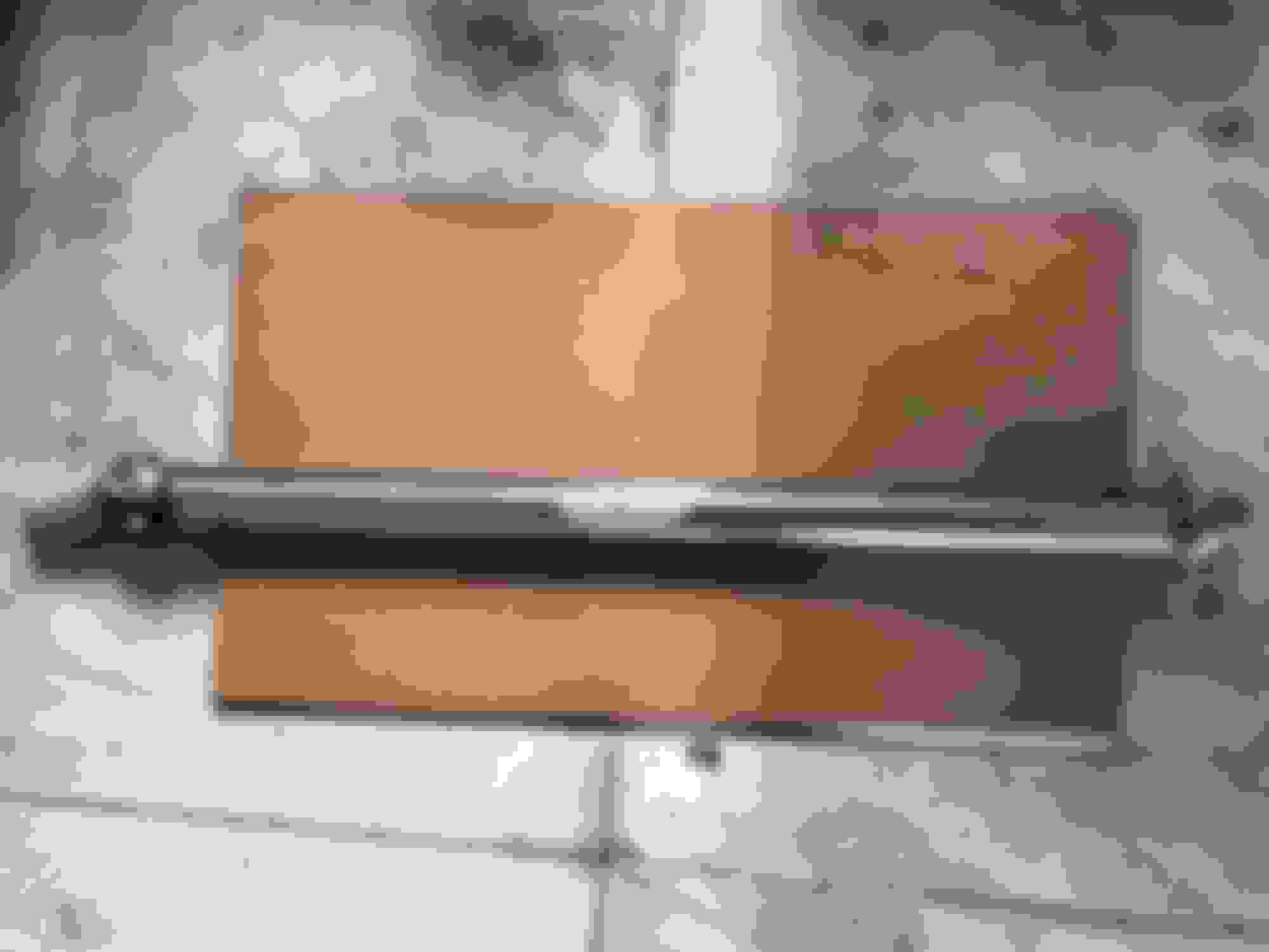
Small update today - I got my new driveshaft back from the local driveshaft shop. I called some of the big name brand shops first and they told me 6-8weeks minimum right now so I looked around for a local driveshaft shop and found one about 15mins from my house. Had a good conversation with the owner on my goals and use case for the car and he suggested a 3" steel shaft with 1350 U-Joints. They use DANA Spicer parts and had everything needed in stock. I got my measurements to them Thursday at lunch and he said it would be ready sometime the next week which I was ok with since I'm not driving this thing for a while yet. Friday (the next day) at 12:55 he called saying it was ready to pick up!
They balanced and clear coated it for me along with supplying the correct 2WD fully splined slip yoke since someone decided to put a 4x4 output yoke in my 2WD Van 4L80e. Admittedly, he said it would "work" but would be sticking out of the trans several inches more than they like to see. Typically they could just cut it down to the correct length, but the machined OD where the seal would ride was pitted beyond use so a new yoke would be needed anyways. To my surprise they used the stronger non-greaseable u-joints and when I asked about it the owner said they use these in hot-rod / high performance street applications because they have fewer failures and unless you are planning to put a bunch of miles on it, the service life isn't an issue.
Center to center of the U-Joint caps is 48.5" on the new unit and somewhere around 54" on the stock shaft. My measurements came out to be correct because it fit right in with no issues.
Got my crimped AC hoses back from Vintage Air last week. Al in, it was about 1 week total that they were gone including shipping there, time there, and then shipping back. Well worth the shipping cost in my mind.
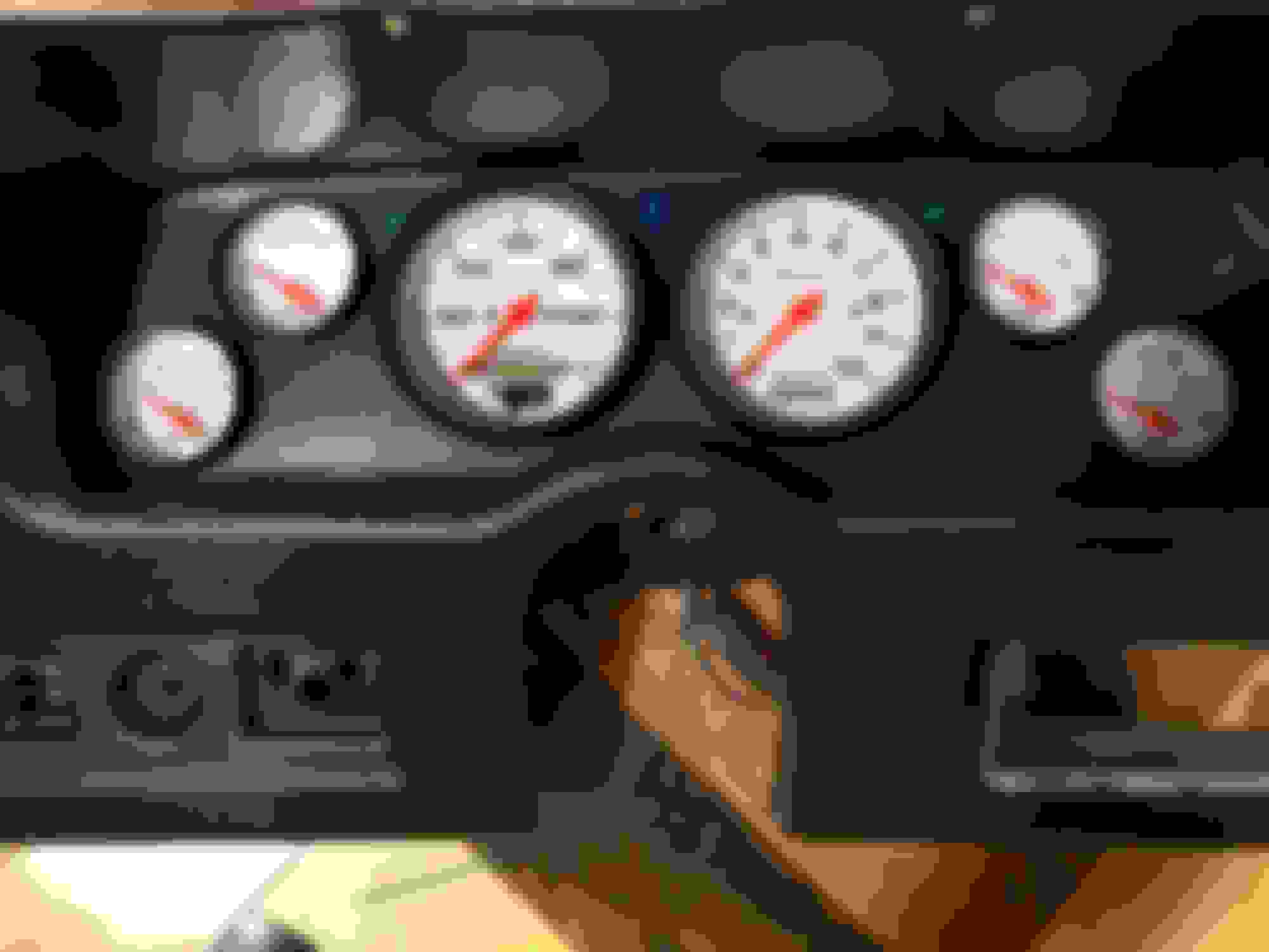
I have decided I want to go away from the Covans Classic dash and go back to using the factory bezel and integrating all 8 gauges into one place so I don't have the racer gauge pod look on my A-pillar. Here is what I ended up with in terms of gauge layout and spacing. I tried to put the most critical guages together in a grouping on the right, but I may have to re-organize them slightly as this forces me to shift the centerline of the Speedo and Tach off-center with the steering column as can be seen below in the offset of my center line to the column opening.
Another key piece of the puzzle was delivered the same day as my AC hoses in the form of my Tanks INC kit. This comes with the fuel injection tank, a walbro 255 lph pump, straps, gauge sending unit, roll-over vent, and fill neck.
The other thing I have been working on is changing my weather-pack connectors to Metri-Pack GT 280 style connectors. There's nothing inherently wrong with the weatherpacks, but the push-on and pull-off forces were unacceptable to me if I ever have to service anything. The Metri-Pack GT 280's use the same crimper, but the push-on and pull-off forces are much more in-line with what I am wanting out of an electrical connector. Plus, I was able to get a connector with more than 4 terminals - I am utilizing pretty much everything from a 12 pin to a 2 pin connector. The position assurance features and seals appear to be much higher quality as well. I also am running my fuel pump wire through my factory fuse block to join up with the harness that goes to the rear of the car. This allows me to run the wire inside the cabin and be out of the elements for as much of the run as possible. If anyone is trying to find what connector type is used in the old GM firewall bulkhead connectors / fuse block connectors, they are GM/Packard 56 or 59 style connectors. I'm not sure how long GM used this in the firewall bulkheads but it it the same type of connector used in things like HEI distributor connectors.
Back on to the fuel system, I completed the mockup and installation of the fuel tank and the new 3/8 hard line, including mounting and plumbing to and from the corvette filter/regulator. I used a combination of my tubing bender and bending by hand to get all the required bends into the hardline. If I had to do it again, I would probably make it in 2 pieces to make installation easier.
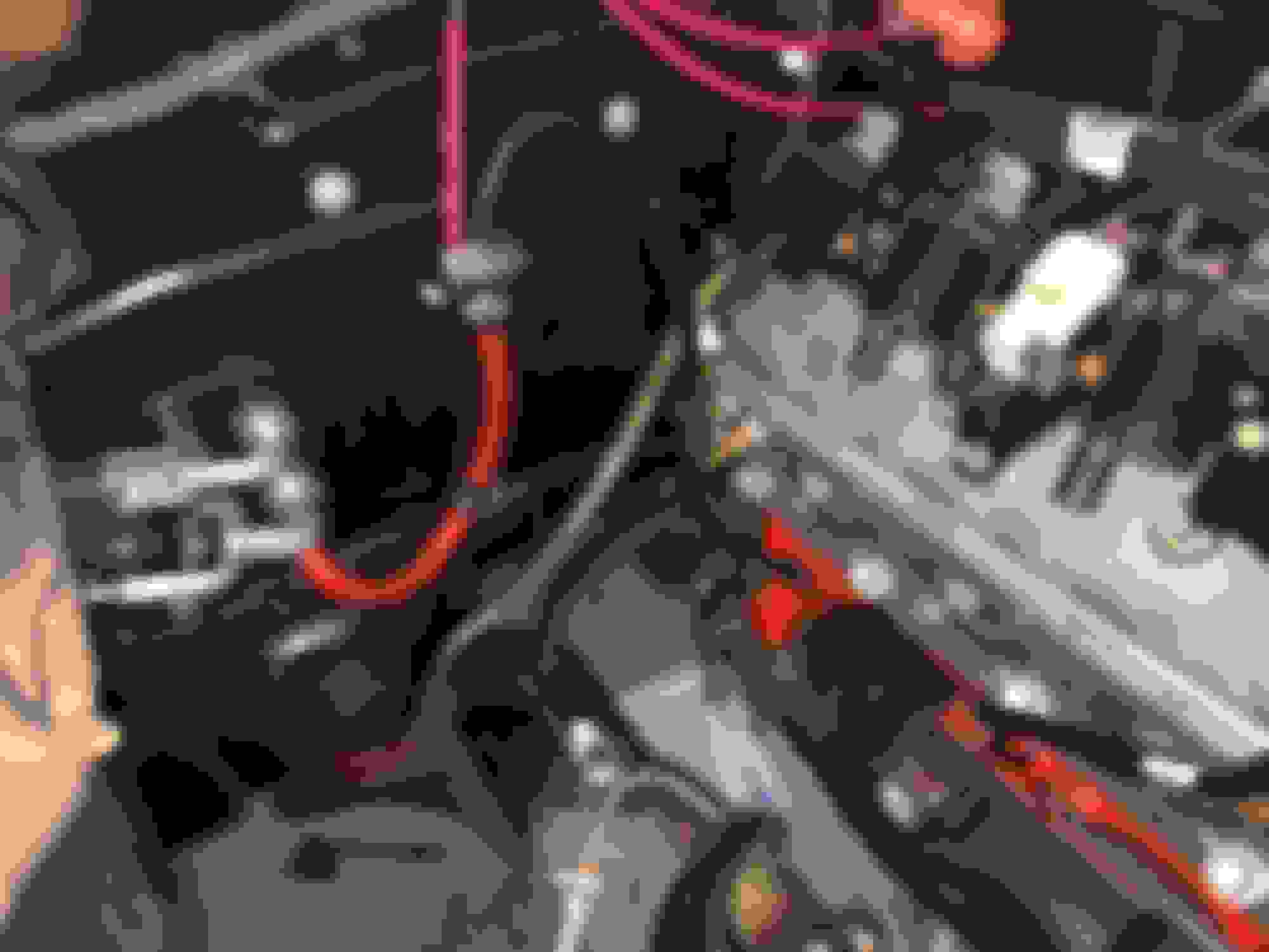
Up next, I got back on the battery re-location to the trunk. I needed to run my positive cable to the front and I had 2 options - drill a hole in the trunk and run the cable outside the car up to the front or route the cable through the passenger cabin under the carpet to the firewall and punch a hole through. I chose the latter as this provides more protection to the cable from the elements and allows better hiding of the cable - at least up to the firewall. I chose to punch through the DSE heater block-off plate I have so that if I ever needed to, I could just get another plate and then the hole would be gone. I also mounted the distribution block there as well since it gave me a nice location to run the starter wire up and over the headers and tuck in nice and tight to the block along with the solenoid wire and crank position sensor wires. Still not 100% sold on how this looks on the firewall, but I'm somewhat committed now. (duct tape on battery cable was temporary while I was mocking up the cable for different routings - the one shown below was my final routing path but I didn't take pics after the cushion clamps were put in place)
My positive cable is routed up over the fenderwell (to maximize trunk space and minimize the chance of it getting pinched on something) and follows the rear firewall down to a factory opening and then it goes under the rear seat to the center of the car.
For the ground cables, I decided to attach the body ground to the same place the rear harness grounds to and I will zip tie the 8 gauge ground cable to the factory harness so it's also out of the way.
For my chassis 1/0 gauge ground wire, I went to the bumper shock mount bolt, sanded down the paint and used a 1/2" flat washer to increase the contact area for a good ground path.
I did run into a little snafu that had me scratching my head all weekend and re-prepping all of my ground locations including sanding the faces of the ground straps. I couldn't get any better than 470 ohms of resistance between my positive and negative battery cables no matter what I did. I even ran new grounds from engine block to chassis, chassis to body and engine to body with no improvement. Still had the 470 ohm bogey that wouldn't improve. The thing that really stumped me was it was directional - meaning it would only register with my multimeter leads one way. If I switched them, it went to open circuit. Finally, I started disconnecting things and doing continuity tests on all of my wires and traced it back to the Alternator. The alternator has 470 ohms of resistance between the charge stud and the case, and only in one direction. I ran the alternator charging wire directly to the cylinder head to take it out of the equation and I had 0 ohms of resistance - perfect continuity. Doing some research, it seems that the LS alternator has a diode and resistor in it's circuitry, so I was chasing my tail for seemingly nothing lol. I compared my Summit alternator to the stock unit and it had 580 ohms of resistance, so the new one is less resistive than that.
**EDIT**
I plugged the chassis harness into the firewall and connected the power wire to the rest of the system (in this case I am powering up my chassis harness from the 1/4" stud on the engine harness fuse/relay block since that's where my 6 AWG wire connects to) and did another measurement on the continuity between the positive and negative battery cables. With the chassis harness hooked up and the alternator connected, I now have continuity both directions. Previously I only had the engine harness connected and did not have my chassis harness plugged in.
Got my gauges installed in the new sheet metal cluster I bent up and have it all mounted in the car now. I decided to go back to the original bezel because it was more solid of a piece and I think it looks better than the all black Covans piece. Plus now I don't need the A-pillar gauge pod so I get more of the sleeper look I am after. I have all 8 gauges right front and center within easy view and they all plug in to the same harness. I did have to order 2 hole saws (3-3/8" and a 2-1/16") as the ones I had 2-1/8" and 3-1/2" & 3-1/4" did not work in my test fit. I used 0.060" aluminum sheet for this and it came out great with my harbor freight brake I acquired. That has since been used on several other brackets I had to fab up and is a nice little unit for the hobbyist.
Also, from one of my prior posts, it looks like I placed my Wideband O2 5V signal in the wrong pin for my PCM - it needs to go to pin 55 on the C1 blue connector which is called "EGR Pintle Position Sensor Signal". From picture #5 in post 98 (the previous post lol) I was able to see that I mistakenly put it in pin 48, so I will have to pull the C1 connector and re-pin it to the correct pin 55.


 03-31-2021, 07:44 AM