

1970 GTO Version 3.0
 06-28-2021, 01:40 PM
#301
TECH Senior Member
Thread Starter
iTrader: (7)

Spent some quality time in the garage yesterday and was able to complete a couple of tasks. This update seems to be growing, and frankly, it has already become a little overwhelming, but I am trying to stay motivated and take it one step at a time.
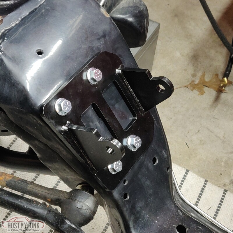
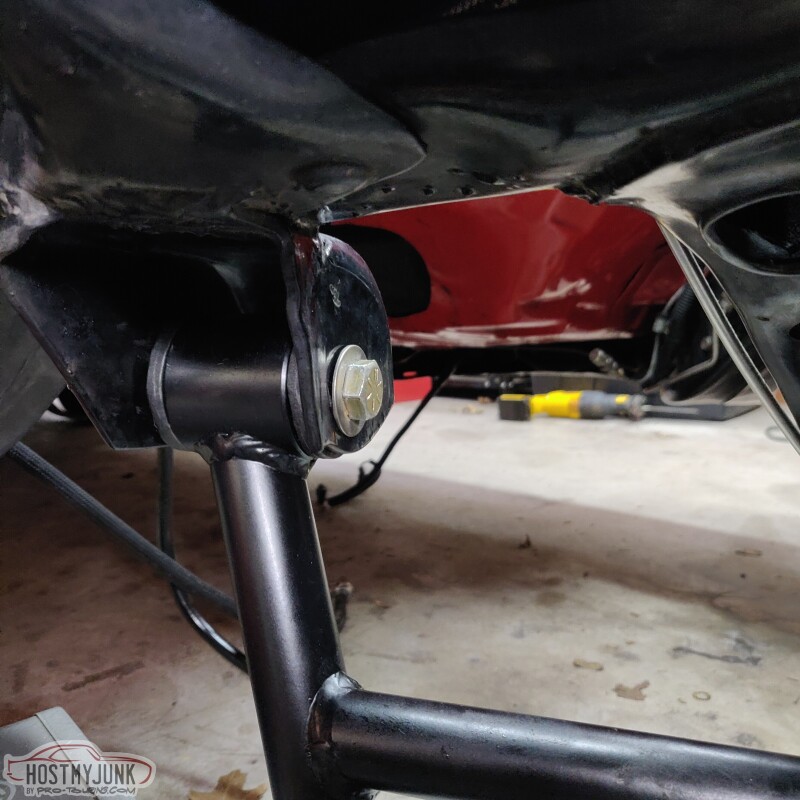
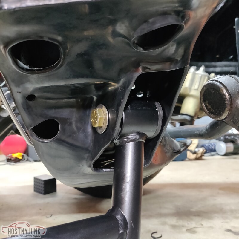
With the old front lower control arm out of the way, it was the perfect opportunity to install the new Holley LS swap engine mounts.
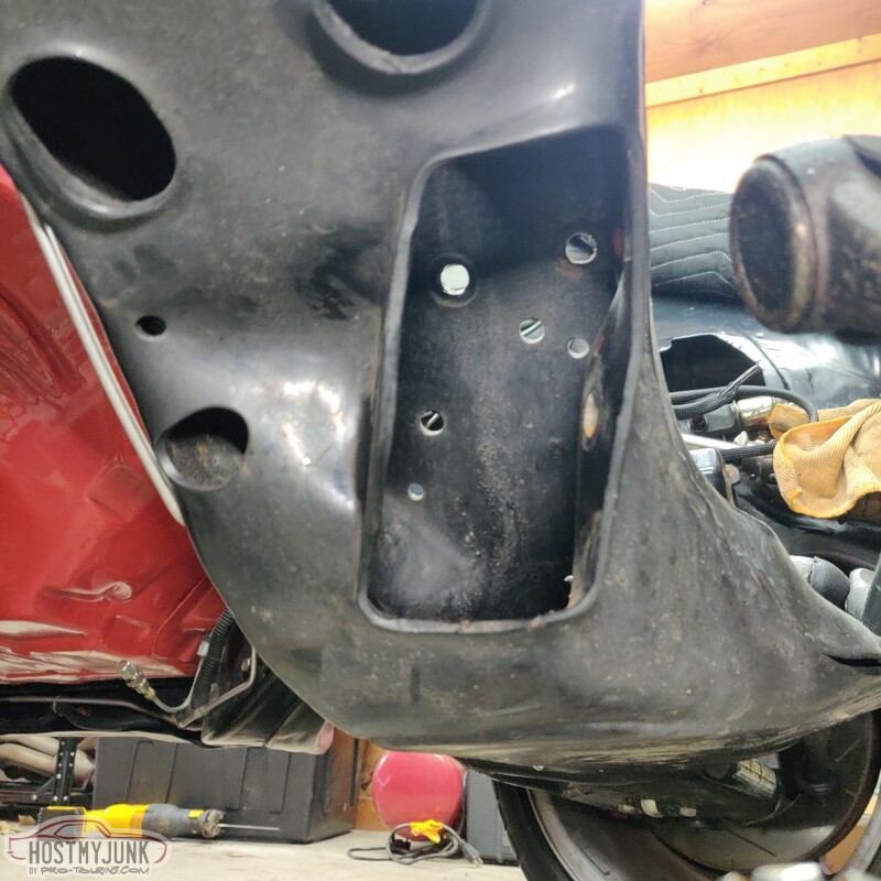
With the nuts easily accessible from the bottom, the old frame stands came right off.
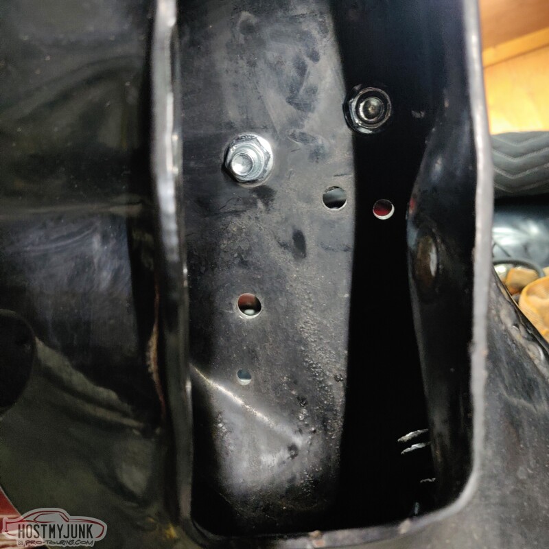
New stands go in place and once again, the easy access makes putting the nuts on very easy.
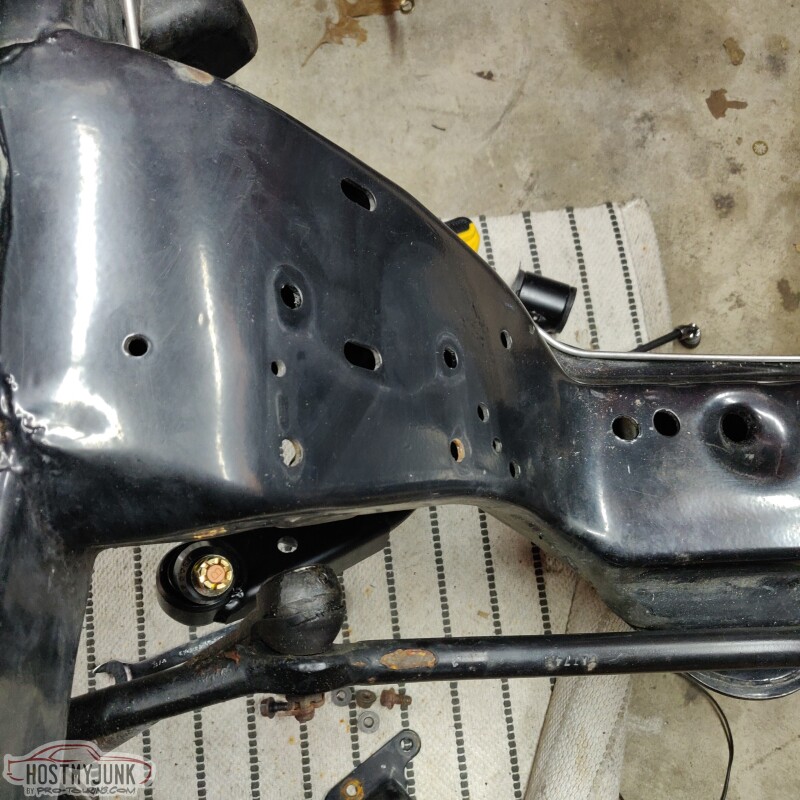
This is a nice shot that compares the old frame stand on the driver's side with the new stand on the passenger side.
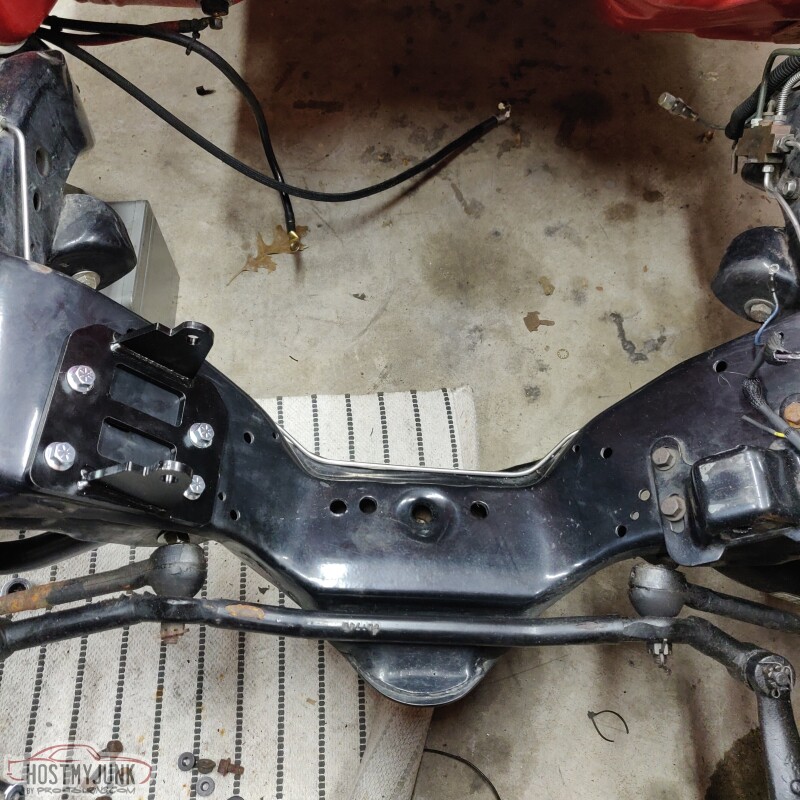
Part of this whole project was to use these Holley mounts. They place the engine as low as possible in the front cradle, which offers better driveline angles. The other benefit is that they use the 4th gen Camaro style engine mounts, which are excellent.
Andrew
With the old front lower control arm out of the way, it was the perfect opportunity to install the new Holley LS swap engine mounts.
With the nuts easily accessible from the bottom, the old frame stands came right off.
New stands go in place and once again, the easy access makes putting the nuts on very easy.
This is a nice shot that compares the old frame stand on the driver's side with the new stand on the passenger side.
Part of this whole project was to use these Holley mounts. They place the engine as low as possible in the front cradle, which offers better driveline angles. The other benefit is that they use the 4th gen Camaro style engine mounts, which are excellent.
Andrew

The following 2 users liked this post by Project GatTagO:
G Atsma (06-28-2021), will69camaro (06-29-2021)
06-28-2021, 02:10 PM
#302


Man. A 5-6k mile chassis lol. That�s CLEAN

The following 3 users liked this post by Jimbo1367:
The following 5 users liked this post by Project GatTagO:
2ToeRacing (07-15-2023), G Atsma (06-28-2021), kwhizz (06-30-2021), Motown 454 (07-01-2021), will69camaro (06-29-2021)
06-29-2021, 04:54 AM
#304
Wow. That held up pretty darn good. Mission accomplished. That�s how howrods should look. Nice and clean.
The following users liked this post:
kwhizz (06-30-2021)
06-30-2021, 09:16 PM
#305

Andrew,
Starting to lay out the engine harness and reading the manual and there is sensor connection labeled Manifold air temp. My L92 is dressed with a LS3 intake and doesn't have a MAT sensor. Did a little searching and looks like I need to order the sensor and it goes in the intake tube? Some are saying it needs to be in the intake. Can you confirm which is best?
Knock sensors. It doesn't appear the Holley engine harness includes connectors for L92 style knock sensors or any type of knock sensors. Are they needed?
I could be missing it but I don't see a wire in the harness that goes to the speedo. I'm using Auto Meter speedo and tach. I did see a tach wire in the harness.
Thanks in advance.
06-30-2021, 10:56 PM
#306
TECH Senior Member

Could MAT = IAT?
07-01-2021, 10:49 AM
#307
TECH Senior Member
Thread Starter
iTrader: (7)
Andrew,
Starting to lay out the engine harness and reading the manual and there is sensor connection labeled Manifold air temp. My L92 is dressed with a LS3 intake and doesn't have a MAT sensor. Did a little searching and looks like I need to order the sensor and it goes in the intake tube? Some are saying it needs to be in the intake. Can you confirm which is best?
Knock sensors. It doesn't appear the Holley engine harness includes connectors for L92 style knock sensors or any type of knock sensors. Are they needed?
I could be missing it but I don't see a wire in the harness that goes to the speedo. I'm using Auto Meter speedo and tach. I did see a tach wire in the harness.
Thanks in advance.
Starting to lay out the engine harness and reading the manual and there is sensor connection labeled Manifold air temp. My L92 is dressed with a LS3 intake and doesn't have a MAT sensor. Did a little searching and looks like I need to order the sensor and it goes in the intake tube? Some are saying it needs to be in the intake. Can you confirm which is best?
Knock sensors. It doesn't appear the Holley engine harness includes connectors for L92 style knock sensors or any type of knock sensors. Are they needed?
I could be missing it but I don't see a wire in the harness that goes to the speedo. I'm using Auto Meter speedo and tach. I did see a tach wire in the harness.
Thanks in advance.
https://rifesensors.com/product/air-...ature-sensors/
If you bought a Gen 4 system with a Gen 4 harness, there are two knock sensor connectors, one for each side of the block.
Do you have a Terminator X Max? The speedo wire needs to be configured in the Trans ICF and then assigned to one of the outputs in the I/O connector. There is no easy option for a Speedo output with a Terminator X.
Andrew
07-01-2021, 10:50 AM
#308
TECH Senior Member
Thread Starter
iTrader: (7)
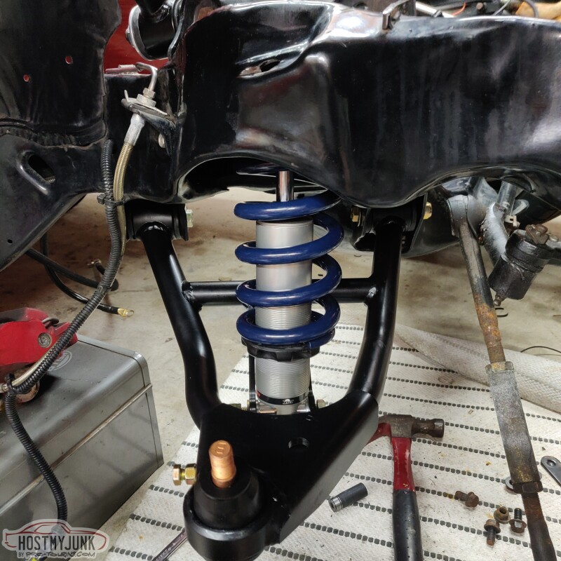
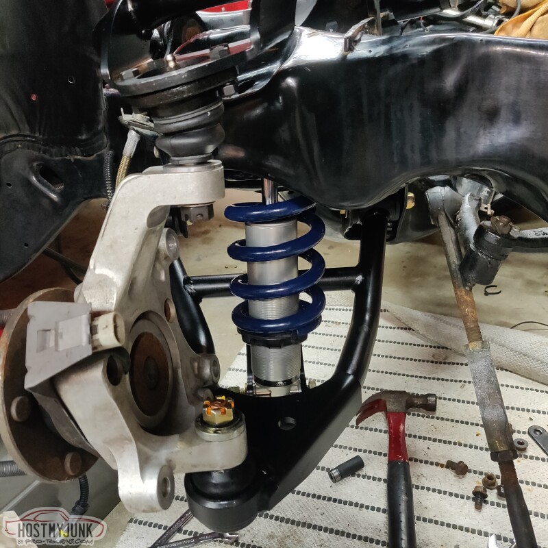
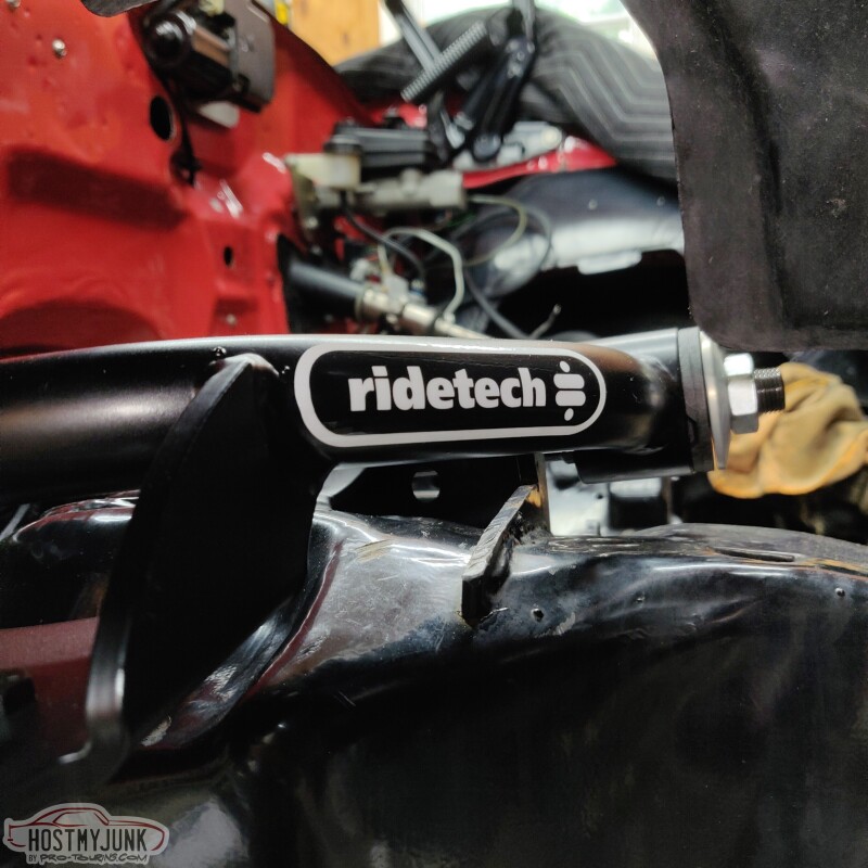
Once the Holley engine mounts were installed, I could install the Ridetech lower control arm. They slipped in very nicely into their pockets.
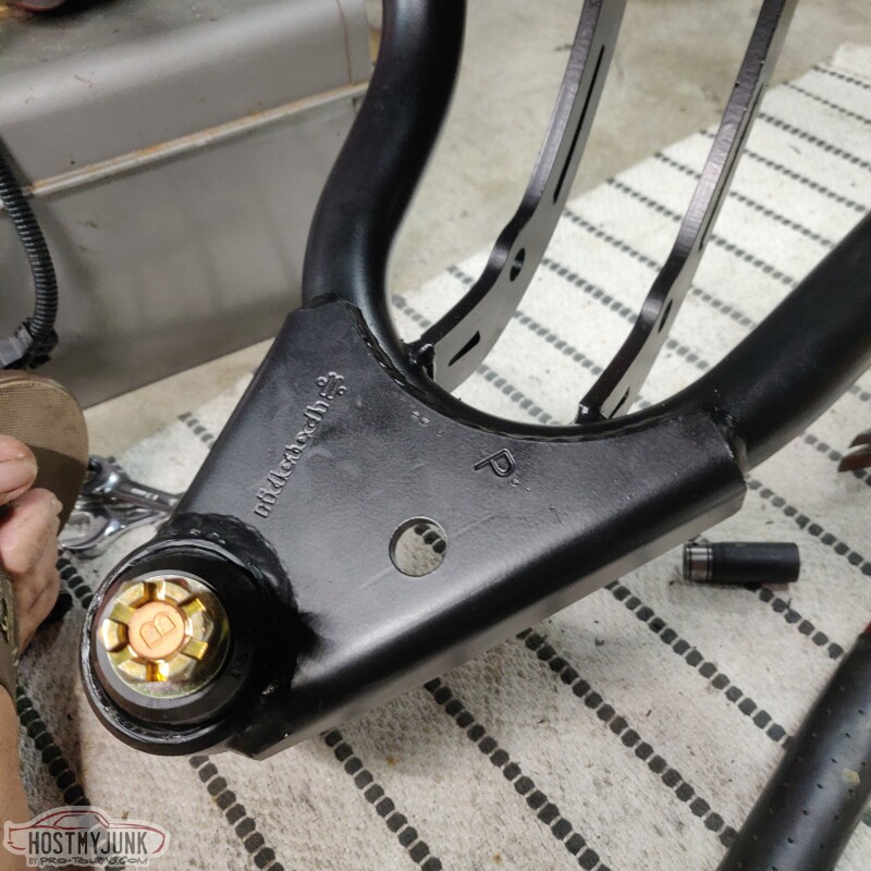
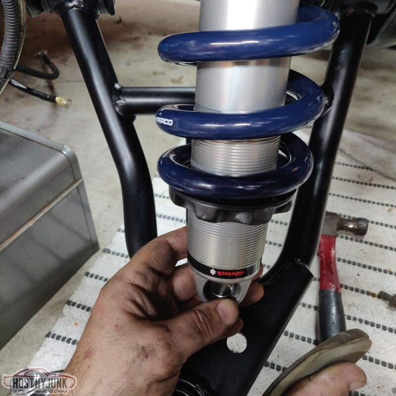
The next step was to install the Ridetech coil over. The upper shock mount needs to be opened up to 3/4" and I did that with a step drill. The upper coil over mount uses a deleon swivel ball assembly which takes care of any misalignment that occurs during suspension travel. It is a slick set-up.
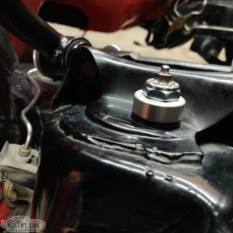
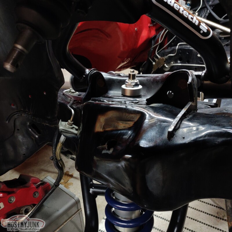
The upper mount gets tightened down enough to take out any slop in the pivot, but not so tight that it binds.
Finally the spindle can be installed and the upper and lower ball joints torqued to spec.
The calipers were pretty grungy with brake dust.
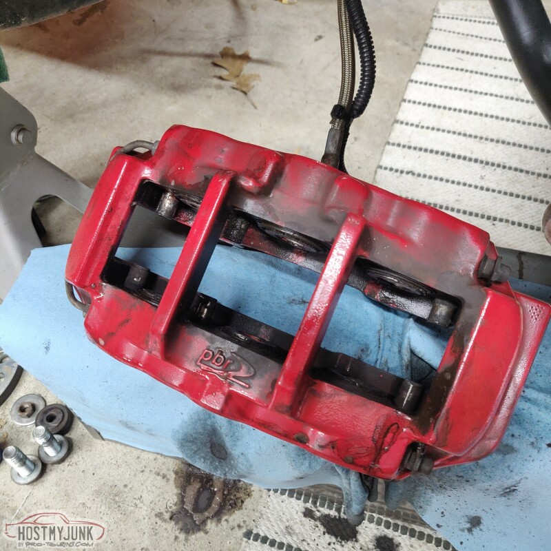
I used some orange degreaser to get them looking more respectable.
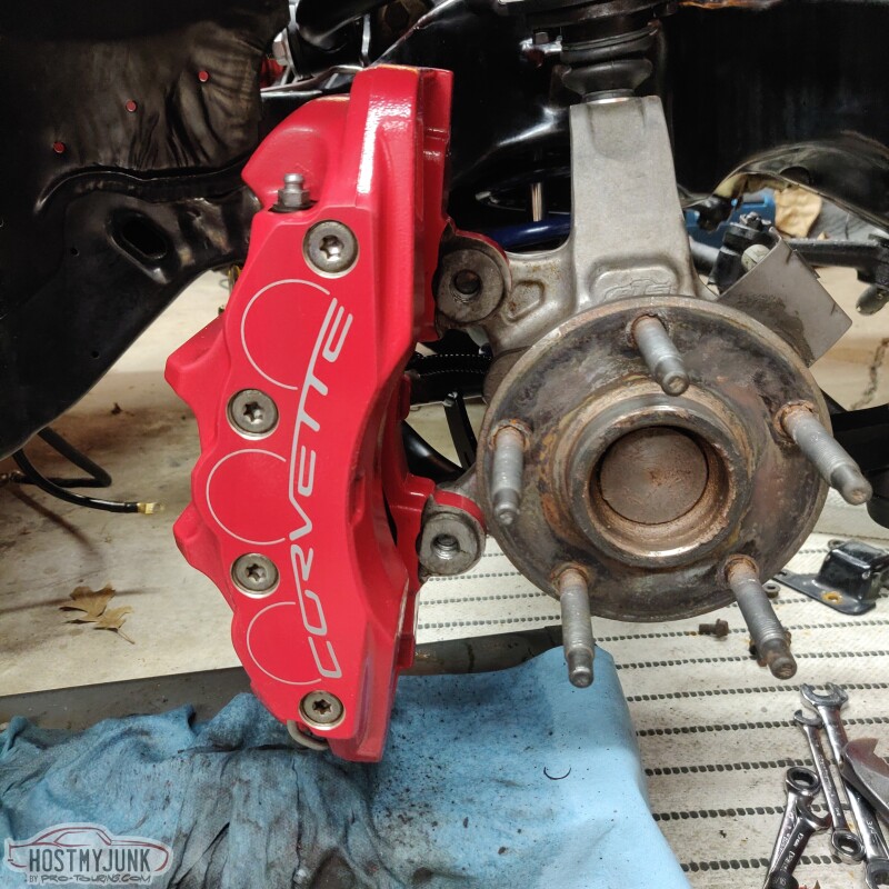
I have new PowerStop rotors and pads that will go on next...
Andrew
The next step was to install the Ridetech coil over. The upper shock mount needs to be opened up to 3/4" and I did that with a step drill. The upper coil over mount uses a deleon swivel ball assembly which takes care of any misalignment that occurs during suspension travel. It is a slick set-up.
The upper mount gets tightened down enough to take out any slop in the pivot, but not so tight that it binds.
Finally the spindle can be installed and the upper and lower ball joints torqued to spec.
The calipers were pretty grungy with brake dust.
I used some orange degreaser to get them looking more respectable.
I have new PowerStop rotors and pads that will go on next...
Andrew
The following users liked this post:
G Atsma (07-01-2021)
07-01-2021, 02:11 PM
#309
Andrew
How quickly could you stop with those big *** calipers? C6 Z51 caliper? What did you use exactly on the rears and how did u like it?
I�ve eyes CCP _Vette knuckle but I want to drive what I have before changing so feel the difference.
Thanks,
Jim
How quickly could you stop with those big *** calipers? C6 Z51 caliper? What did you use exactly on the rears and how did u like it?
I�ve eyes CCP _Vette knuckle but I want to drive what I have before changing so feel the difference.
Thanks,
Jim
07-01-2021, 03:05 PM
#310
TECH Senior Member
Andrew- Did you get a complete package, or order a la carte?
That thing is gonna handle and stop, now! Ridetech has the right pieces...
That thing is gonna handle and stop, now! Ridetech has the right pieces...
07-01-2021, 03:26 PM
#311
Andrew thanks for the reply.
My bad on the knock sensors. I haven't uncoiled the harness I checked again and they are there big as life.
Thanks for the detail on the MAT sensor and speedo signal.
I do have the Terminator X Max. 550-928
My bad on the knock sensors. I haven't uncoiled the harness I checked again and they are there big as life.
Thanks for the detail on the MAT sensor and speedo signal.
I do have the Terminator X Max. 550-928
07-01-2021, 04:17 PM
#312
TECH Senior Member
Thread Starter
iTrader: (7)
Andrew
The following users liked this post:
G Atsma (07-01-2021)
07-01-2021, 04:20 PM
#313
TECH Senior Member
Thread Starter
iTrader: (7)
Andrew
The following users liked this post:
G Atsma (07-01-2021)
The following users liked this post:
Project GatTagO (07-01-2021)
The following users liked this post:
Motown 454 (07-02-2021)
07-01-2021, 09:59 PM
#316
A bit off topic but on my 68 C10 project I had spindle mods so I could add 13" C5 brakes. With the 20" rims I added the C5 13" brakes looked a bit small. After a bit of research I found out the 14" ZO6 rotors were a bolt on. I just remade the caliper brackets 1/2" wider for the 14" rotors. The swept area on the C5 standard and Z06 is the same.
The following 2 users liked this post by LS1 TJ:
Motown 454 (07-02-2021), Project GatTagO (07-02-2021)

The following users liked this post:
Project GatTagO (07-02-2021)
07-02-2021, 02:57 PM
#318
TECH Senior Member
Thread Starter
iTrader: (7)
Got the hubs cleaned up and applied some anti-seize before slipping on a new PowerStop rotor.
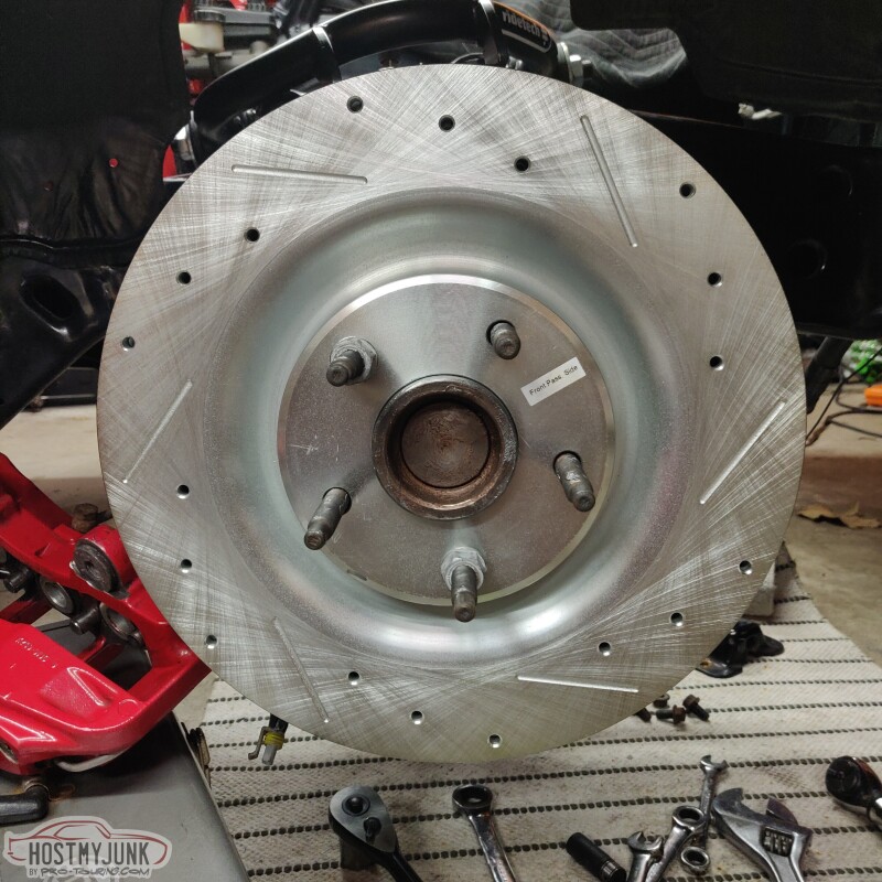
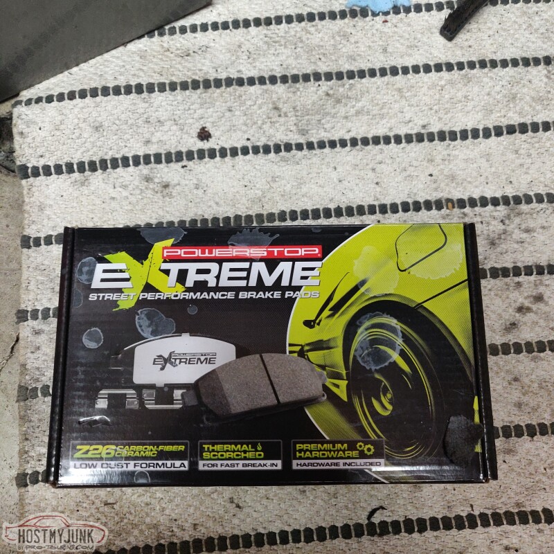
After talking with Tobin at Kore3, decided to go with the Z26 carbon ceramic brake pads.
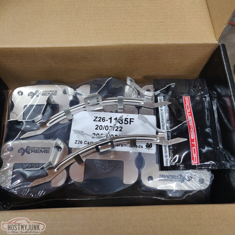
The kit included pads and new retaining clips.
Now the passenger side is completely buttoned up...
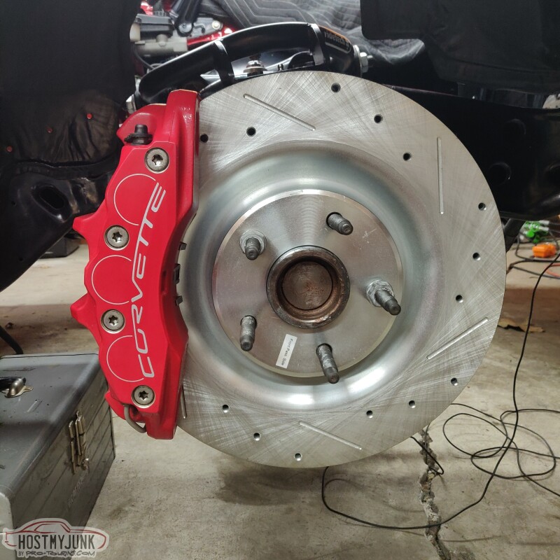
Except I am pretty sure that I installed the pads upside down...<facepalm>
Andrew
After talking with Tobin at Kore3, decided to go with the Z26 carbon ceramic brake pads.
The kit included pads and new retaining clips.
Now the passenger side is completely buttoned up...
Except I am pretty sure that I installed the pads upside down...<facepalm>
Andrew
07-02-2021, 04:05 PM
#319
TECH Senior Member
Upside down??? You mean maybe inside (lining) facing out? I can't visualize upside down....