

1970 GTO Version 3.0
 05-13-2021, 09:09 PM
#261


Andrew I have the Holley Terminator X Max waiting to be be installed. I have a 160 SLP degree stat from a previous project that I have never used. I'm running all 2002 Camaro FEA. Is the 160 degree stat too low for good tuning with the Holley system?
I do not to start a temp stat what is best war. Just looking for guidance.
I do not to start a temp stat what is best war. Just looking for guidance.
 05-13-2021, 09:48 PM
#262
TECH Senior Member
Thread Starter
iTrader: (7)

Andrew I have the Holley Terminator X Max waiting to be be installed. I have a 160 SLP degree stat from a previous project that I have never used. I'm running all 2002 Camaro FEA. Is the 160 degree stat too low for good tuning with the Holley system?
I do not to start a temp stat what is best war. Just looking for guidance.
I do not to start a temp stat what is best war. Just looking for guidance.
Andrew
The following users liked this post:
G Atsma (05-13-2021)
05-13-2021, 10:20 PM
#263
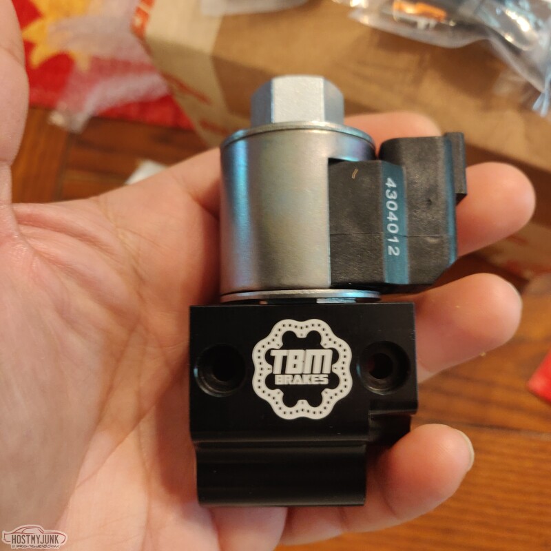
Looks nice. I checked their web page to see if these line locks can be pumped multiple times. I didn't see anything about that on their page.
I've always used the TCI Rollstops. They let you pump up the line lock before or after you engage it. And pump it again if you want more pressure. It has a one way valve that accumulates pressure.
I've always used the TCI Rollstops. They let you pump up the line lock before or after you engage it. And pump it again if you want more pressure. It has a one way valve that accumulates pressure.
05-14-2021, 04:55 AM
#264

As with anything, You take it with a grain of salt. Eventually you might end up with a full salt shaker LOL.
The following users liked this post:
G Atsma (05-14-2021)
05-14-2021, 04:57 AM
#265
How are the Rife Sensors price wise compared to GM sensors?
 05-14-2021, 02:10 PM
#267
they are easily found on Holleys� homepage. Look for the brands and click on Earls. Fuel injection fittings they Have several types so don�t get discouraged if it doesn�t pop up right away. Plan on $35. Or so.
05-14-2021, 09:39 PM
#268
Another question or two.. On my 80 Camaro the stock harness has a 12 volt lead to the distributor that is hot in start and run. Will that work for the Holley ECM? As I did a bit of research the Holley ECM likes a direct connection to the battery. Can the constant 12 volt connection be connected to the starter stud or does it have to be connected directly to the battery stud?
Don't know if this helps anyone but I like to run -3 ss braided from the cylinder head vent tube to the radiator. I cut the vent tube pipe off the stock vent tube crossover and drill and tap it for 1/8" pipe. You an make your own line but the stock car folks have many -3 brake lines configurations already made that they use for brake lines.
Don't know if this helps anyone but I like to run -3 ss braided from the cylinder head vent tube to the radiator. I cut the vent tube pipe off the stock vent tube crossover and drill and tap it for 1/8" pipe. You an make your own line but the stock car folks have many -3 brake lines configurations already made that they use for brake lines.
05-15-2021, 11:02 AM
#270
05-15-2021, 10:13 PM
#271
Thanks for all the replies. This is the first time I've used the Holley system on a LS. I have a number of OEM LS swaps using aftermarket harnesses under my belt so I will have many questions in regards to make sure I get the Holley system correct. Nothing against Holley it's just very new to me.
My internet service here at home is not the best so youtube videos are not so good.
I really rely on the good advice on this web site.
Thanks again for all your help.
My internet service here at home is not the best so youtube videos are not so good.
I really rely on the good advice on this web site.
Thanks again for all your help.
The following users liked this post:
will69camaro (05-15-2021)
05-17-2021, 08:30 PM
#272
TECH Senior Member
Thread Starter
iTrader: (7)
A lot more expensive...
https://www.holley.com/products/plum...ts/AT991966ERL
The main power wires should go to the battery. There is another red wire that comes off the main harness. It supplies power to the relay that is in the harness. This red wire be connected to the starter stud.
Andrew
Another question or two.. On my 80 Camaro the stock harness has a 12 volt lead to the distributor that is hot in start and run. Will that work for the Holley ECM? As I did a bit of research the Holley ECM likes a direct connection to the battery. Can the constant 12 volt connection be connected to the starter stud or does it have to be connected directly to the battery stud?
Don't know if this helps anyone but I like to run -3 ss braided from the cylinder head vent tube to the radiator. I cut the vent tube pipe off the stock vent tube crossover and drill and tap it for 1/8" pipe. You an make your own line but the stock car folks have many -3 brake lines configurations already made that they use for brake lines.
Don't know if this helps anyone but I like to run -3 ss braided from the cylinder head vent tube to the radiator. I cut the vent tube pipe off the stock vent tube crossover and drill and tap it for 1/8" pipe. You an make your own line but the stock car folks have many -3 brake lines configurations already made that they use for brake lines.
Andrew
05-17-2021, 08:31 PM
#273
TECH Senior Member
Thread Starter
iTrader: (7)
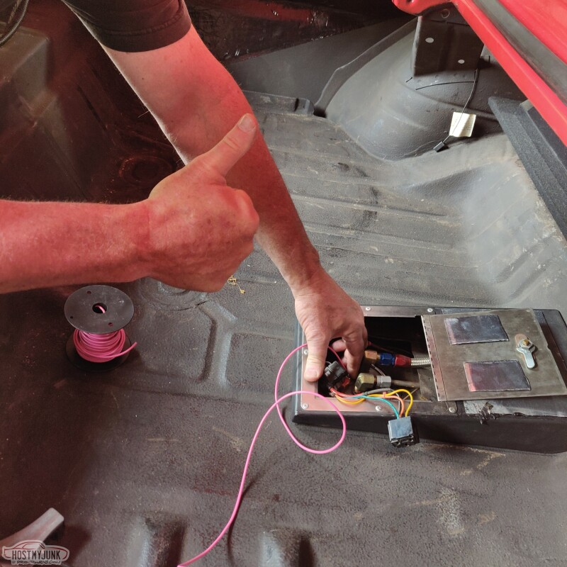
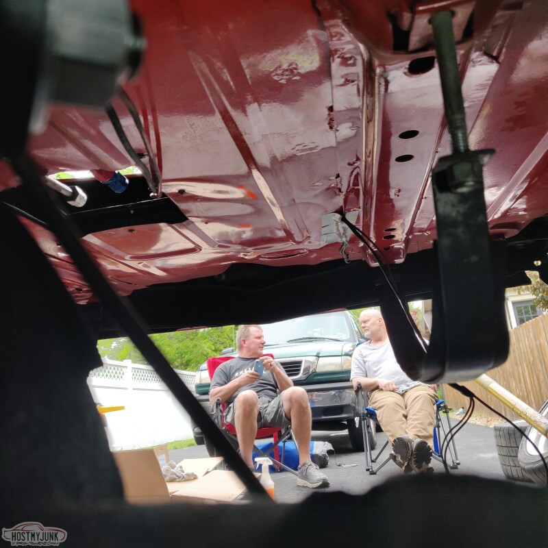
Friday evening my friend Tom flew in from Alabama to help me with the installation of the complete Ridetech suspension kit. Since the fuel tank was being replaced anyway, we figured it would be a good idea to get it out of the way to make working on the rear suspension easier. Of course, some knucklehead parked the car with about half a tank of gas in it still.
Having the battery in the trunk and having an access panel to the top of the tank made this a lot easier. This allowed us to quickly hotwire the pump to the battery and start draining the tank.
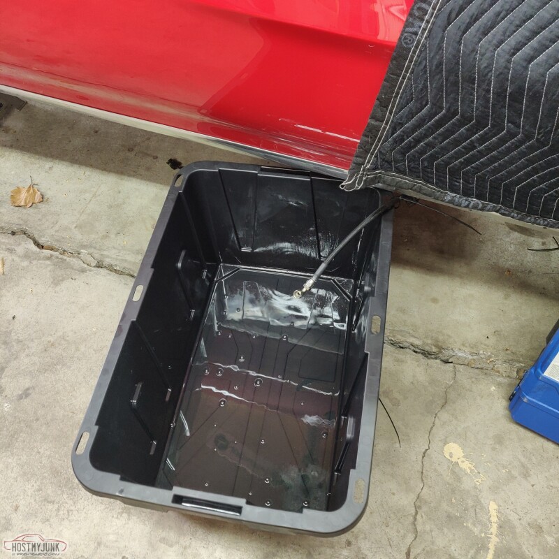
We followed all safety precautions and used an approved container to hold the fuel and then transferred it to other vehicles in the driveway, which thankfully had room in their tanks.
With the tank removed, it was a lot easier to get at the rear suspension components and the first thing to be removed were the 20 year old Hal shocks (who remembers those?). Surprisingly they were still charged up well and not leaking at all.
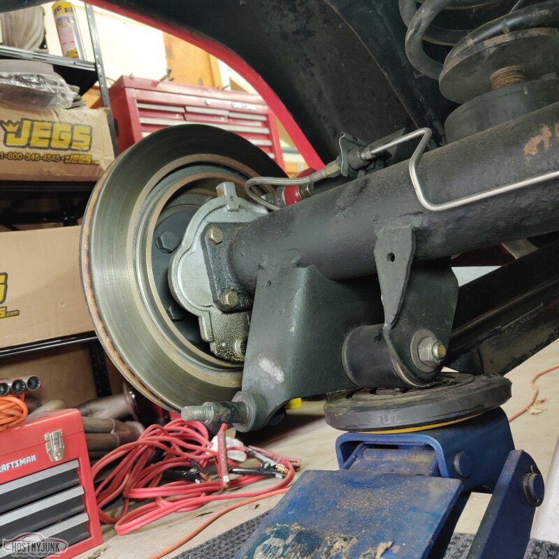
Next up was removing the springs and the adjustable lower spring mounts that I installed back in 2008.
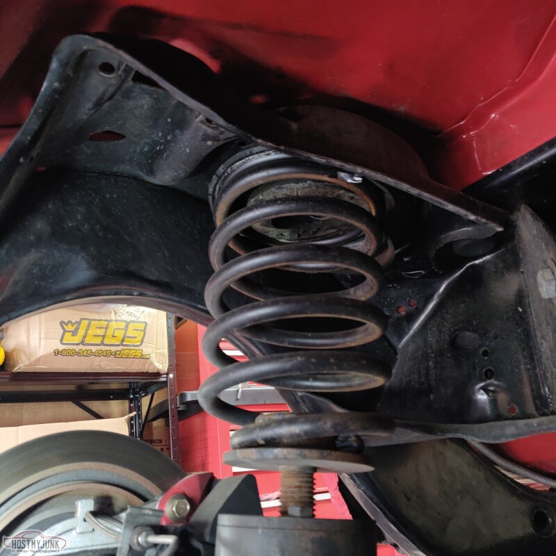
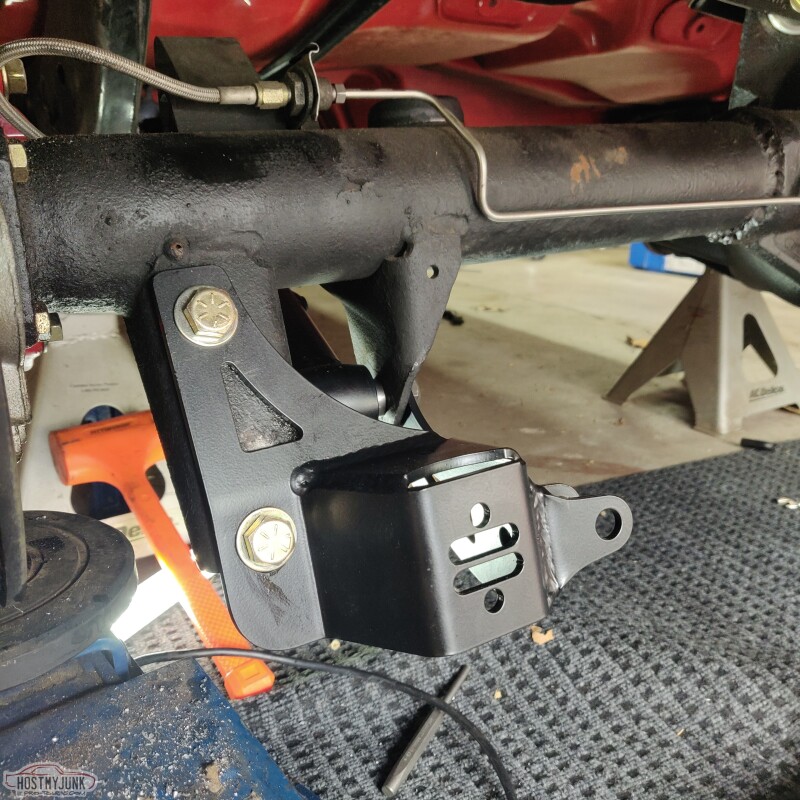
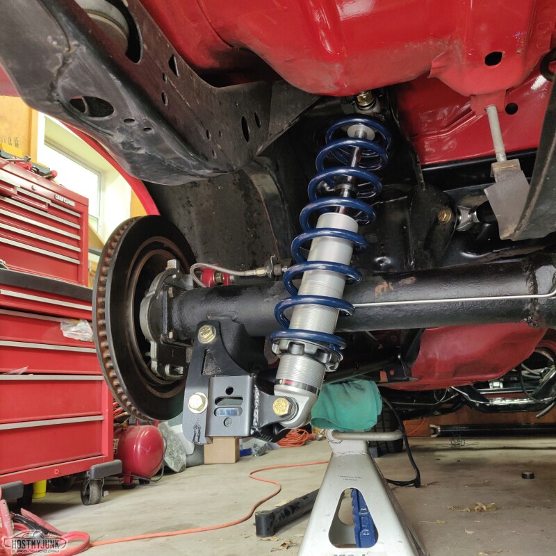
Next up was installing the upper coilover mount. Ridetech provides a nice bracket that bolts to where the old upper shock mount used to be. The bracket needs to be oriented so the mount is offset towards the center of the car and the bolts should go in from the bottom, with the nuts on top. Obviously I had the bolts going the other way in this picture, but it was changed later on when I discovered that the bolts that holds the shock at the top will hit the bolts holding the top mount.

More to come...
Andrew
Having the battery in the trunk and having an access panel to the top of the tank made this a lot easier. This allowed us to quickly hotwire the pump to the battery and start draining the tank.
We followed all safety precautions and used an approved container to hold the fuel and then transferred it to other vehicles in the driveway, which thankfully had room in their tanks.
With the tank removed, it was a lot easier to get at the rear suspension components and the first thing to be removed were the 20 year old Hal shocks (who remembers those?). Surprisingly they were still charged up well and not leaking at all.
Next up was removing the springs and the adjustable lower spring mounts that I installed back in 2008.
Next up was installing the upper coilover mount. Ridetech provides a nice bracket that bolts to where the old upper shock mount used to be. The bracket needs to be oriented so the mount is offset towards the center of the car and the bolts should go in from the bottom, with the nuts on top. Obviously I had the bolts going the other way in this picture, but it was changed later on when I discovered that the bolts that holds the shock at the top will hit the bolts holding the top mount.
More to come...
Andrew
The following 2 users liked this post by Project GatTagO:
2ToeRacing (07-15-2023), will69camaro (05-17-2021)
05-17-2021, 08:53 PM
#274
TECH Senior Member
Thread Starter
iTrader: (7)
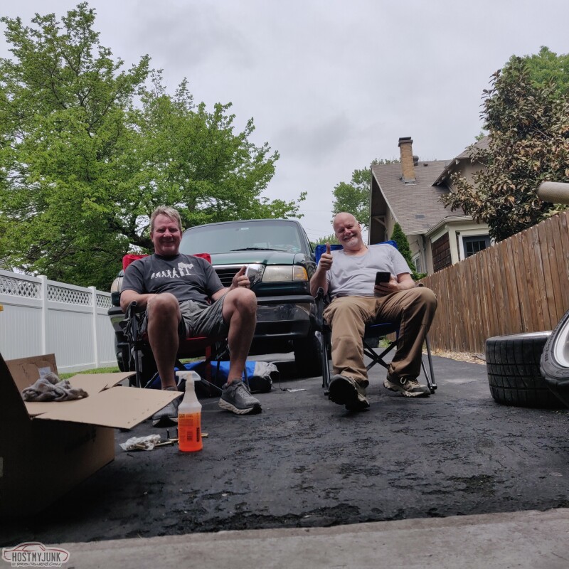
While I was working under the car, my helpers were encouraging me the whole time.
After carefully reading the Ridetech instructions, Tom and Ron helped with assembling the rear coilovers.
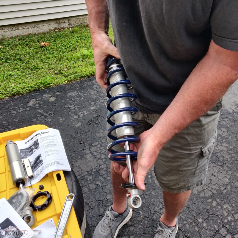
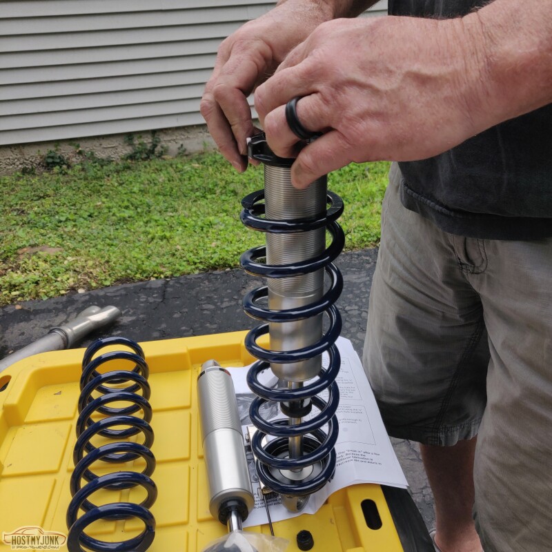
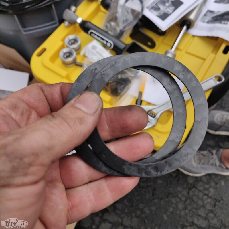
Instead of using torrington thrust washers, Ridetech uses these really slick delrin washers at both ends of the spring. I was a little skeptical at first, but they work awesome. Turning the adjustment collars was super easy.
The lower coilover bracket uses the existing hole that used to hold the old shock mount, then it is also captured by the bolt that fastens the lower control arm, and there is a third bolt above the old shock mount location. This hole needs to be drilled. Everything went together as it should.
More to come...
Andrew
After carefully reading the Ridetech instructions, Tom and Ron helped with assembling the rear coilovers.
Instead of using torrington thrust washers, Ridetech uses these really slick delrin washers at both ends of the spring. I was a little skeptical at first, but they work awesome. Turning the adjustment collars was super easy.
The lower coilover bracket uses the existing hole that used to hold the old shock mount, then it is also captured by the bolt that fastens the lower control arm, and there is a third bolt above the old shock mount location. This hole needs to be drilled. Everything went together as it should.
More to come...
Andrew
The following 2 users liked this post by Project GatTagO:
2ToeRacing (07-15-2023), will69camaro (05-17-2021)
05-17-2021, 09:17 PM
#275
TECH Senior Member
Thread Starter
iTrader: (7)
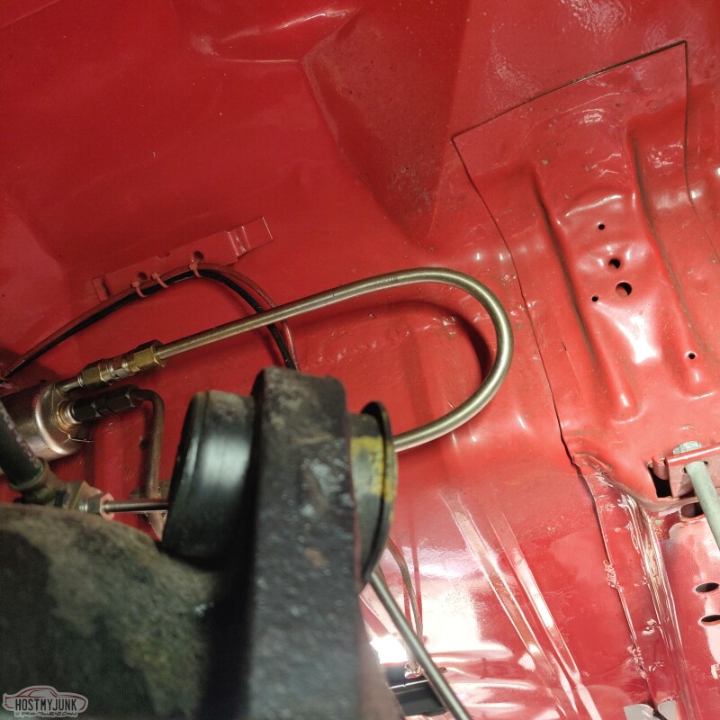
Please ignore those ugly fuel lines. I don't know what I was thinking when I did all that. I promise it all seemed like a good idea at the time. It's all going away...
The focus is on replacing the upper rubber bushings on the axle housing, with new Ridetech R-joint bushings.
Ridetech offers a tool that serves as both the bushing removal and installation tool. Having an impact gun for this is a must, as it made this job really simple and clean. Once the tool was lined up, the old bushings just popped out.
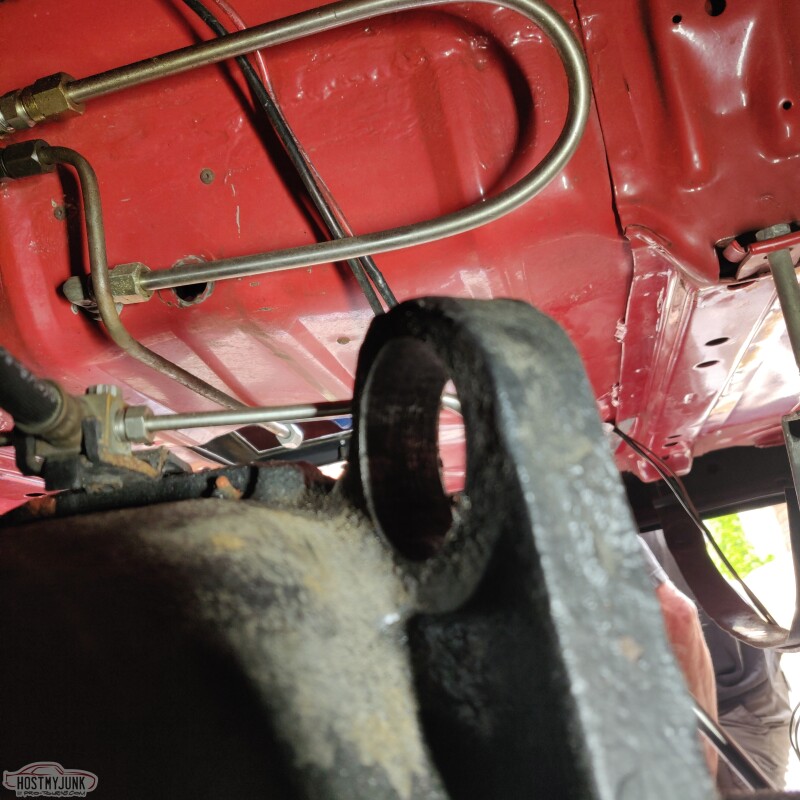
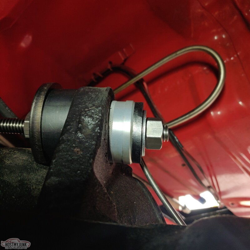
Here is the Ridetech tool setup to install the new R-joints. There is very little room on the driver's side bushing as it is very close to the diff housing. Ridetech cleverly designed the tool with relief cuts to clear the diff housing, so the rod is aligned square.
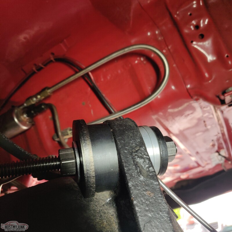
The bushing is installed about halfway in this picture. It needs to be driven in all the way to the little shoulder on the R-joint.
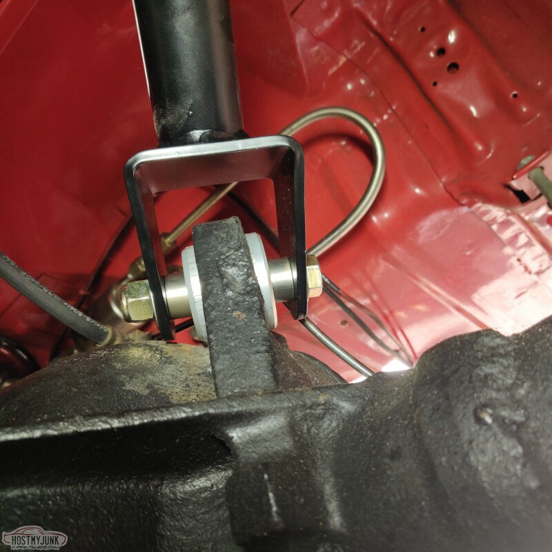
The frame side joint of the new control arms was a bolt in deal. We adjusted the length of the upper control arms to match the length of the old control arms, to keep the pinion angle the same and locate the rear axle in the same location laterally.
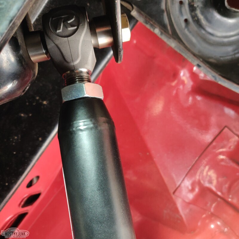
Finally, the arms were bolted to the new R-joints in the axle housing.
More to come...
Andrew
The focus is on replacing the upper rubber bushings on the axle housing, with new Ridetech R-joint bushings.
Ridetech offers a tool that serves as both the bushing removal and installation tool. Having an impact gun for this is a must, as it made this job really simple and clean. Once the tool was lined up, the old bushings just popped out.
Here is the Ridetech tool setup to install the new R-joints. There is very little room on the driver's side bushing as it is very close to the diff housing. Ridetech cleverly designed the tool with relief cuts to clear the diff housing, so the rod is aligned square.
The bushing is installed about halfway in this picture. It needs to be driven in all the way to the little shoulder on the R-joint.
The frame side joint of the new control arms was a bolt in deal. We adjusted the length of the upper control arms to match the length of the old control arms, to keep the pinion angle the same and locate the rear axle in the same location laterally.
Finally, the arms were bolted to the new R-joints in the axle housing.
More to come...
Andrew
05-17-2021, 09:28 PM
#276
TECH Senior Member
Thread Starter
iTrader: (7)
With the control arms bolted up (I didn't take any pictures of the lower arms being installed, because it was a remove and replace procedure), it was time to install the coilover shock in its place. The rebound adjustment **** is located at the top and I positioned it so it faced the center of the car. I should be able to reach it with the car on the ground. Some have suggested mounting the coilover so the adjuster is at the bottom, but then that makes adjusting the spring collars more challenging. Plus, I like the way it looks this way...
The process was repeated on the passenger side, which wrapped up the installation in the rear.
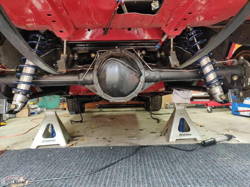
My helpers approved.
That is all for now...
Andrew
The process was repeated on the passenger side, which wrapped up the installation in the rear.
My helpers approved.
That is all for now...
Andrew
The following 3 users liked this post by Project GatTagO:
The following users liked this post:
Project GatTagO (05-17-2021)
05-18-2021, 04:56 AM
#278
That�s a nice clean car
The following users liked this post:
Project GatTagO (05-18-2021)
05-20-2021, 09:58 PM
#279
TECH Senior Member
Thread Starter
iTrader: (7)
I finally got all of my wiring supplies and decided to spend a few hours in the garage this afternoon between tuning appointments.
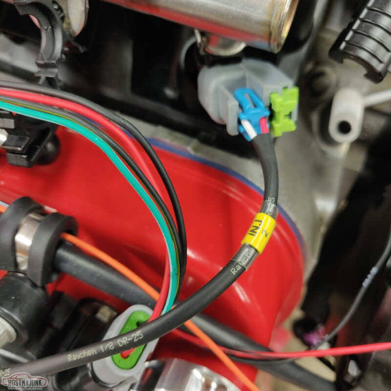
I used 1/8" Raychem DR-25 to protect the delicate wires for the injectors.
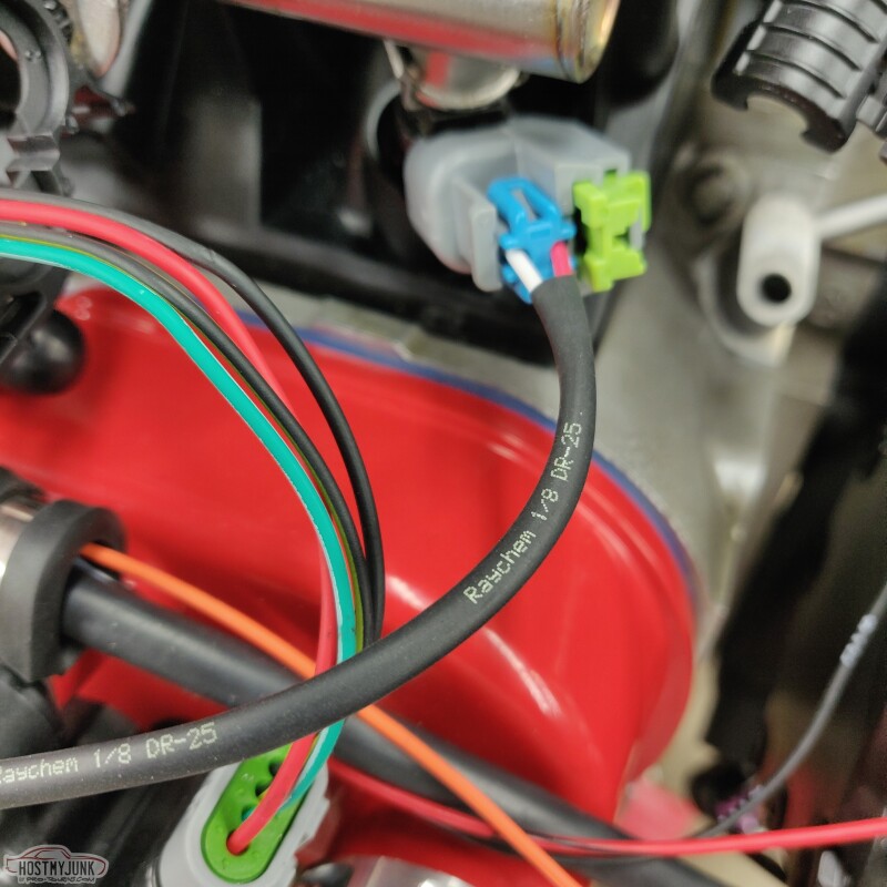
I also added labels with clear heat shrink over the top.
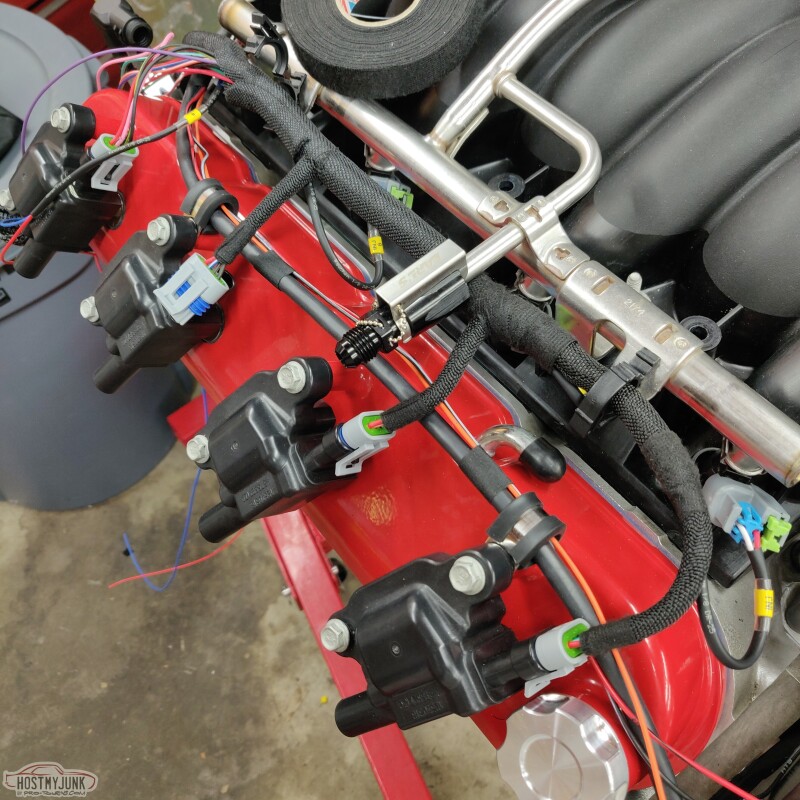
Since I didn't build the coil sub harness from scratch, I was limited as to what I could do for wire protection. Holley uses TechFlex F6 split loom on all of their harnesses. While it works well, I find it not as flexible as I like and it doesn't have a very tight weave, so wires can be seen.
After doing a little digging around on the TechFlex website, I saw a F6 variant called F6 woven. It has a tight weave that covers the wires more fully, and it is more flexible than regular F6.
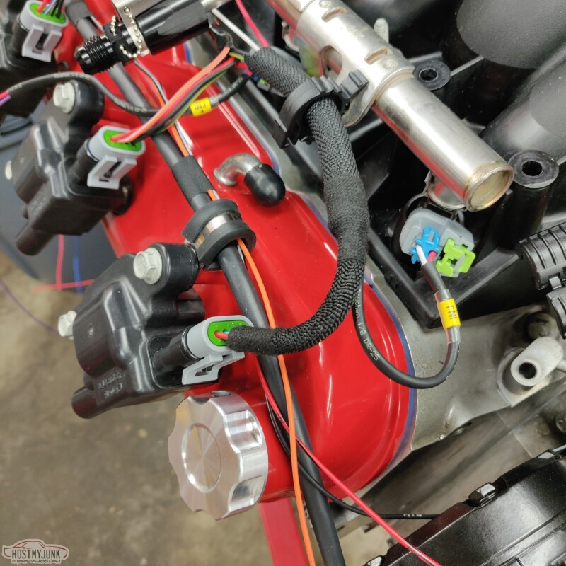
I used the Tessa "fuzzy" harness tape at the junctions. It blends in with the F6 woven pretty nicely.
Wirecare.com has an excellent Deutsch connector configuration guide on their website. They not only offer the basic connectors but also a full assortment of accessories. I got a selection of straight and 90 degree connector "backs" and also some handy connector mounting brackets.
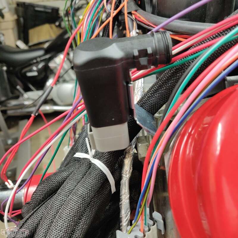
There should be just enough room between the heads and the firewall to mount the coil connectors back there. If it is too tight, I can always straighten out that little bracket to reduce the offset.
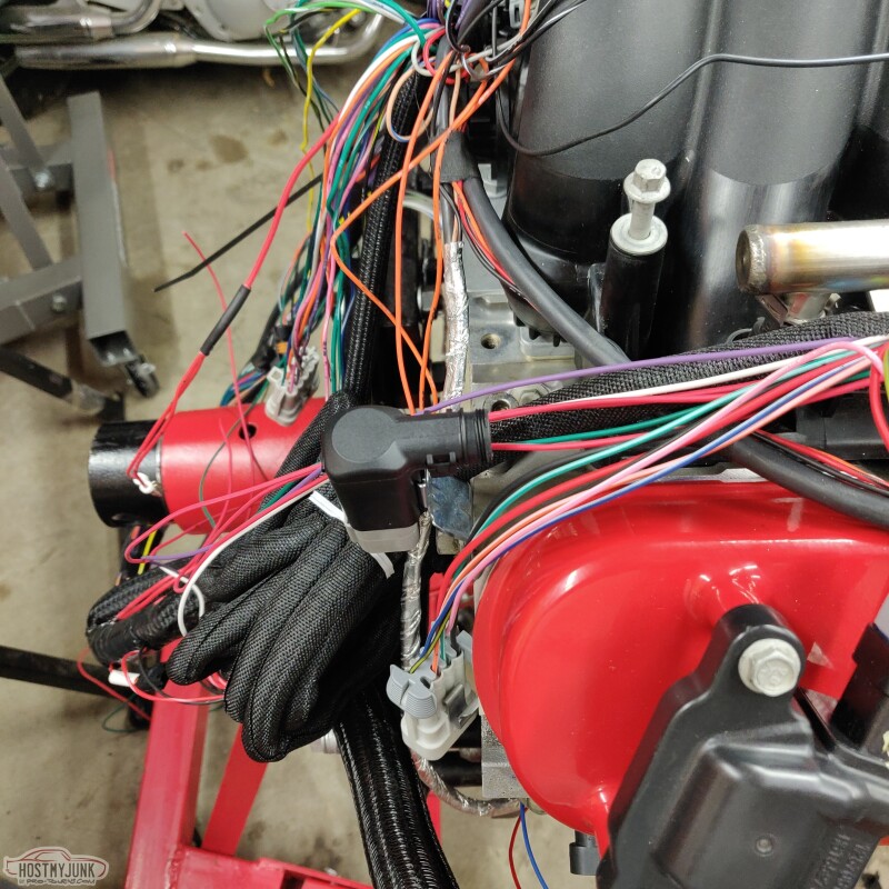
Andrew
I used 1/8" Raychem DR-25 to protect the delicate wires for the injectors.
I also added labels with clear heat shrink over the top.
Since I didn't build the coil sub harness from scratch, I was limited as to what I could do for wire protection. Holley uses TechFlex F6 split loom on all of their harnesses. While it works well, I find it not as flexible as I like and it doesn't have a very tight weave, so wires can be seen.
After doing a little digging around on the TechFlex website, I saw a F6 variant called F6 woven. It has a tight weave that covers the wires more fully, and it is more flexible than regular F6.
I used the Tessa "fuzzy" harness tape at the junctions. It blends in with the F6 woven pretty nicely.
Wirecare.com has an excellent Deutsch connector configuration guide on their website. They not only offer the basic connectors but also a full assortment of accessories. I got a selection of straight and 90 degree connector "backs" and also some handy connector mounting brackets.
There should be just enough room between the heads and the firewall to mount the coil connectors back there. If it is too tight, I can always straighten out that little bracket to reduce the offset.
Andrew
Last edited by Project GatTagO; 05-20-2021 at 10:05 PM.
The following 2 users liked this post by Project GatTagO:
Sway Tale (06-05-2021), will69camaro (05-21-2021)
05-21-2021, 03:08 AM
#280
Looks great Andrew. When I first seen the pic showing the fuzzy harness tape, I thought � where did he get that cool fabric heat shrink� Lol. It really does blend in nicely.
Wirecare.com really has a lot of cool products. I�m glad you brought it up. I bought my F6 spit loom there years ago, but I forgot what the website was.
thanks for sharing your build
jim
Wirecare.com really has a lot of cool products. I�m glad you brought it up. I bought my F6 spit loom there years ago, but I forgot what the website was.
thanks for sharing your build
jim
The following users liked this post:
Project GatTagO (05-21-2021)